Page 1027 of 1640

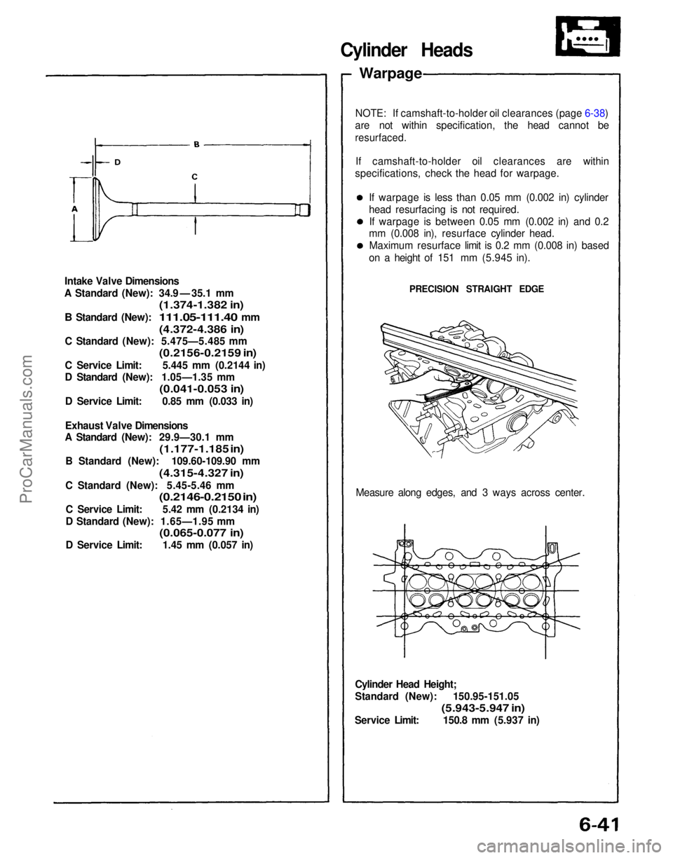
Intake Valve Dimensions
A Standard (New): 34.9 — 35.1 mm
(1.374-1.382 in)
B
Standard (New):
111.05-111.40
mm
(4.372-4.386 in)
C Standard (New): 5.475—5.485 mm
(0.2156-0.2159 in)
C Service Limit: 5.445 mm (0.2144 in)
D Standard (New): 1.05—1.35 mm
(0.041-0.053 in)
D Service Limit: 0.85 mm (0.033 in)
Exhaust Valve Dimensions
A Standard (New): 29.9—30.1 mm
(1.177-1.185 in)
B Standard (New): 109.60-109.90 mm
(4.315-4.327 in)
C Standard (New): 5.45-5.46 mm
(0.2146-0.2150 in)
C Service Limit: 5.42 mm (0.2134 in)
D Standard (New): 1.65—1.95 mm
(0.065-0.077 in)
D Service Limit: 1.45 mm (0.057 in)
Cylinder Head Height;
Standard (New): 150.95-151.05
(5.943-5.947 in)
Service Limit: 150.8 mm (5.937 in) Measure along edges, and 3 ways across center.
NOTE: If camshaft-to-holder oil clearances (page 6-38)
are not within specification, the head cannot be
resurfaced.
If camshaft-to-holder oil clearances are within
specifications, check the head for warpage.
Cylinder Heads
Warpage
If warpage is less than 0.05 mm (0.002 in) cylinder
head resurfacing is not required.If warpage is between 0.05 mm (0.002 in) and 0.2
mm (0.008 in), resurface cylinder head.
Maximum resurface limit is 0.2 mm (0.008 in) based
on a height of 151 mm (5.945 in).
PRECISION STRAIGHT EDGEProCarManuals.com
Page 1028 of 1640

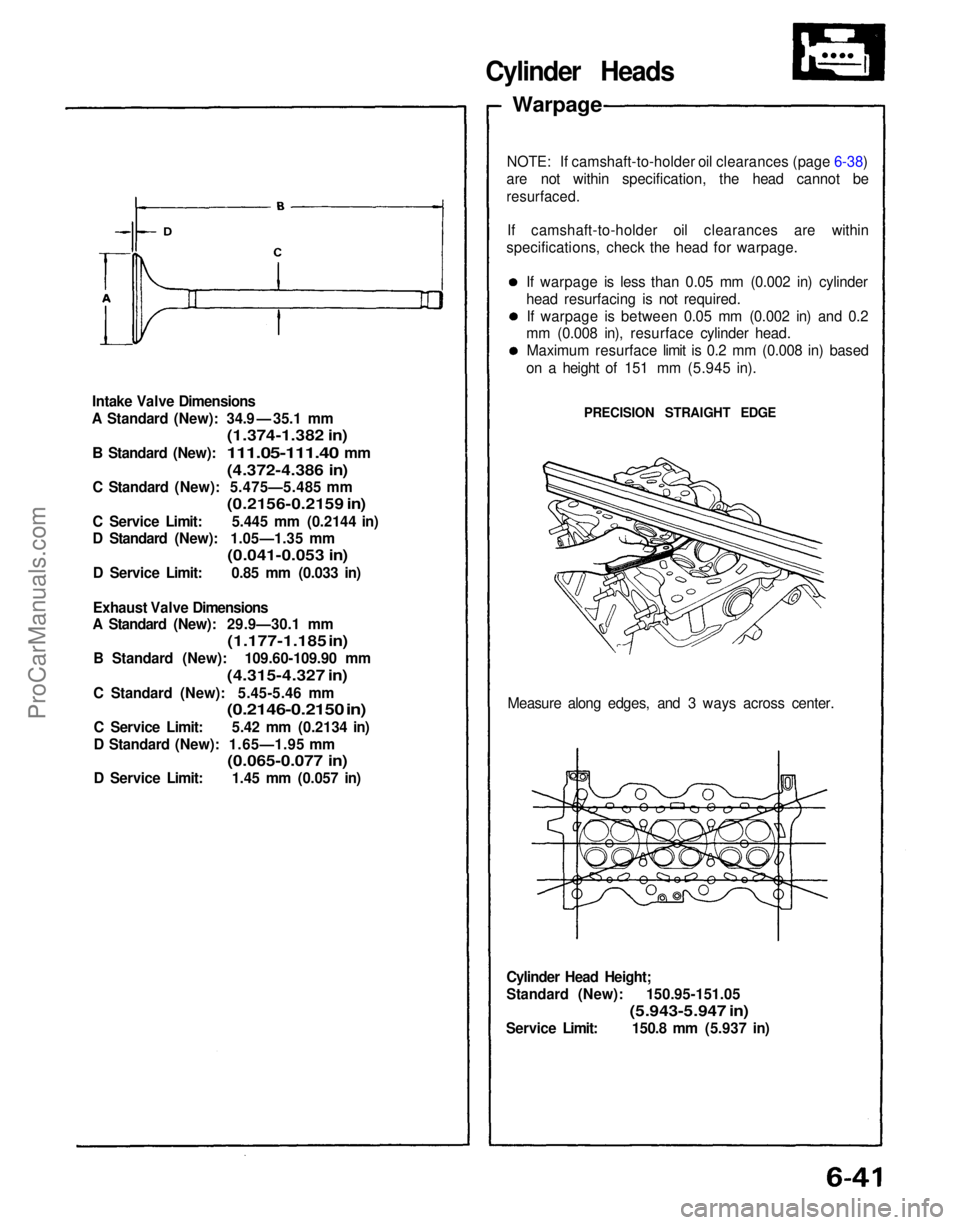
Intake Valve Dimensions
A Standard (New): 34.9 — 35.1 mm
(1.374-1.382 in)
B
Standard (New):
111.05-111.40
mm
(4.372-4.386 in)
C Standard (New): 5.475—5.485 mm
(0.2156-0.2159 in)
C Service Limit: 5.445 mm (0.2144 in)
D Standard (New): 1.05—1.35 mm
(0.041-0.053 in)
D Service Limit: 0.85 mm (0.033 in)
Exhaust Valve Dimensions
A Standard (New): 29.9—30.1 mm
(1.177-1.185 in)
B Standard (New): 109.60-109.90 mm
(4.315-4.327 in)
C Standard (New): 5.45-5.46 mm
(0.2146-0.2150 in)
C Service Limit: 5.42 mm (0.2134 in)
D Standard (New): 1.65—1.95 mm
(0.065-0.077 in)
D Service Limit: 1.45 mm (0.057 in)
Cylinder Head Height;
Standard (New): 150.95-151.05
(5.943-5.947 in)
Service Limit: 150.8 mm (5.937 in) Measure along edges, and 3 ways across center.
NOTE: If camshaft-to-holder oil clearances (page 6-38)
are not within specification, the head cannot be
resurfaced.
If camshaft-to-holder oil clearances are within
specifications, check the head for warpage.
Cylinder Heads
Warpage
If warpage is less than 0.05 mm (0.002 in) cylinder
head resurfacing is not required.If warpage is between 0.05 mm (0.002 in) and 0.2
mm (0.008 in), resurface cylinder head.
Maximum resurface limit is 0.2 mm (0.008 in) based
on a height of 151 mm (5.945 in).
PRECISION STRAIGHT EDGEProCarManuals.com
Page 1578 of 1640

Seat Belts
Inspection
Retractor Inspection
1. With the retractor installed, check that the belt can be pulled out freely.
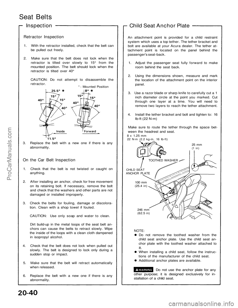
2. Make sure that the belt does not lock when the retractor is tilted over slowly to 15° from the
mounted position. The belt should lock when the
retractor is tilted over 40°
CAUTION: Do not attempt to disassemble the
retractor.
*: Mounted Position
3. Replace the belt with a new one if there is any abnormality.
On the Car Belt Inspection
1. Check that the belt is not twisted or caught on
anything.
2. After installing an anchor, check for free movement on its retaining bolt. If necessary, remove the boltand check that the washers and other parts are not
damaged or installed improperly.
3. Check the belts for fouling, damage or discolora- tion. Clean with a shop towel if fouled.
CAUTION: Use only soap and water to clean. Dirt build-up in the metal loops of the seat belt an-
chors can cause the belts to retract slowly. Wipe
the inside of the loops with a clean cloth dampened in isopropyl alcohol.
4. Check that the belt does not lock when pulled out slowly. The belt is designed to lock only during a
sudden stop or impact.
5. Make sure that the belt will retract automatically when released.
6. Replace the belt with a new one if there is any abnormality.
NOTE:
Do not remove the toothed washer from the
child seat anchor plate. Use the child seat an-
chor plate with the toothed washer attached to
it.
When installing a child seat, follow the instruc-
tions of the manufacturer of the child seat. Additional anchor plates are available.
Do not use the anchor plate for any
other purpose; it is designed exclusively for in-
stallation of a child seat.
246 mm
(62.5
in)
100 mm
(25.4
in)
CHILD SEAT
ANCHOR PLATE
TOOTHED WASHER
25 mm
(1 in)
8 x
1.25
mm
22 N·m (2.2 kg-m, 16 Ib-ft) An attachment point is provided for a child restraint
system which uses a top tether. The tether bracket and
bolt are available at your Acura dealer. The tether at-
tachment point is located on the panel behind the passenger's seat-back.
1. Adjust the passenger seat fully forward to make room behind the seat back.
2. Using the dimensions shown, measure and mark the location of the attachment point on the interior
panel.
3. Use a razor blade or sharp knife to carefully cut a 1 inch diameter circle at the point you marked. Cut
through one layer at a time. You will need to
remove two layers to reach the tether attachment.
4. Install the tether bracket and bolt and tighten to: 16
Ib-ft (22 N·m)
Make sure to route the tether through the space bet-
ween the headrest and seat. Child Seat Anchor PlateProCarManuals.com