1991 ACURA NSX jump cable
[x] Cancel search: jump cablePage 304 of 1640
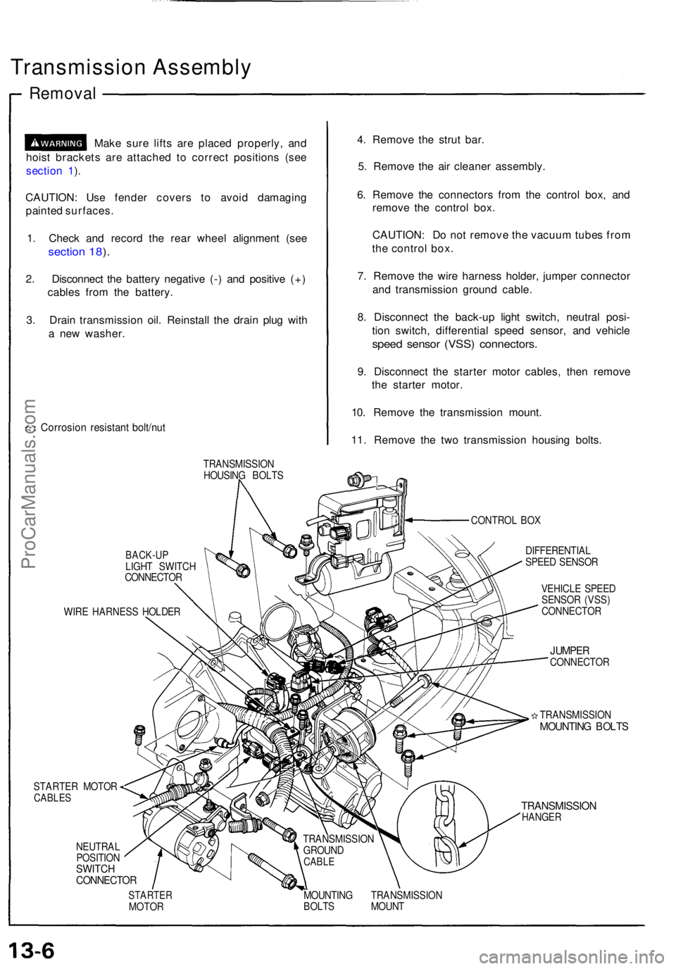
Transmission Assembl y
Removal
Make sur e lift s ar e place d properly , an d
hois t bracket s ar e attache d t o correc t position s (se e
sectio n 1 ).
CAUTION : Us e fende r cover s t o avoi d damagin g
painte d surfaces .
1 . Chec k an d recor d th e rea r whee l alignmen t (se e
sectio n 18 ).
2 . Disconnec t th e batter y negativ e (- ) an d positiv e (+ )
cable s fro m th e battery .
3 . Drai n transmissio n oil . Reinstal l th e drai n plu g wit h
a ne w washer .
Corrosio n resistan t bolt/nu t
4. Remov e th e stru t bar .
5 . Remov e th e ai r cleane r assembly .
6 . Remov e th e connector s fro m th e contro l box , an d
remov e th e contro l box .
CAUTION : D o no t remov e th e vacuu m tube s fro m
th e contro l box .
7 . Remov e th e wir e harnes s holder , jumpe r connecto r
an d transmissio n ground cable.
8 . Disconnec t th e back-u p ligh t switch , neutra l posi -
tio n switch , differentia l spee d sensor , an d vehicl e
speed senso r (VSS ) connectors .
9. Disconnec t th e starte r moto r cables , the n remov e
th e starte r motor .
10 . Remov e th e transmissio n mount .
11 . Remov e th e tw o transmissio n housin g bolts .
TRANSMISSIO N
HOUSIN G BOLT S
CONTROL BO X
BACK-U PLIGHT SWITC H
CONNECTO R
WIR E HARNES S HOLDE R
STARTER MOTOR
CABLES
NEUTRA L
POSITIO N
SWITCHCONNECTO R
DIFFERENTIA L
SPEE D SENSO R
VEHICL E SPEE D
SENSO R (VSS )
CONNECTO R
JUMPERCONNECTO R
TRANSMISSIO N
MOUNTING BOLT S
TRANSMISSIO NHANGER
STARTE RMOTOR MOUNTIN
G TRANSMISSIO N
BOLT S MOUN T
TRANSMISSIO
N
GROUN D
CABLE
ProCarManuals.com
Page 355 of 1640
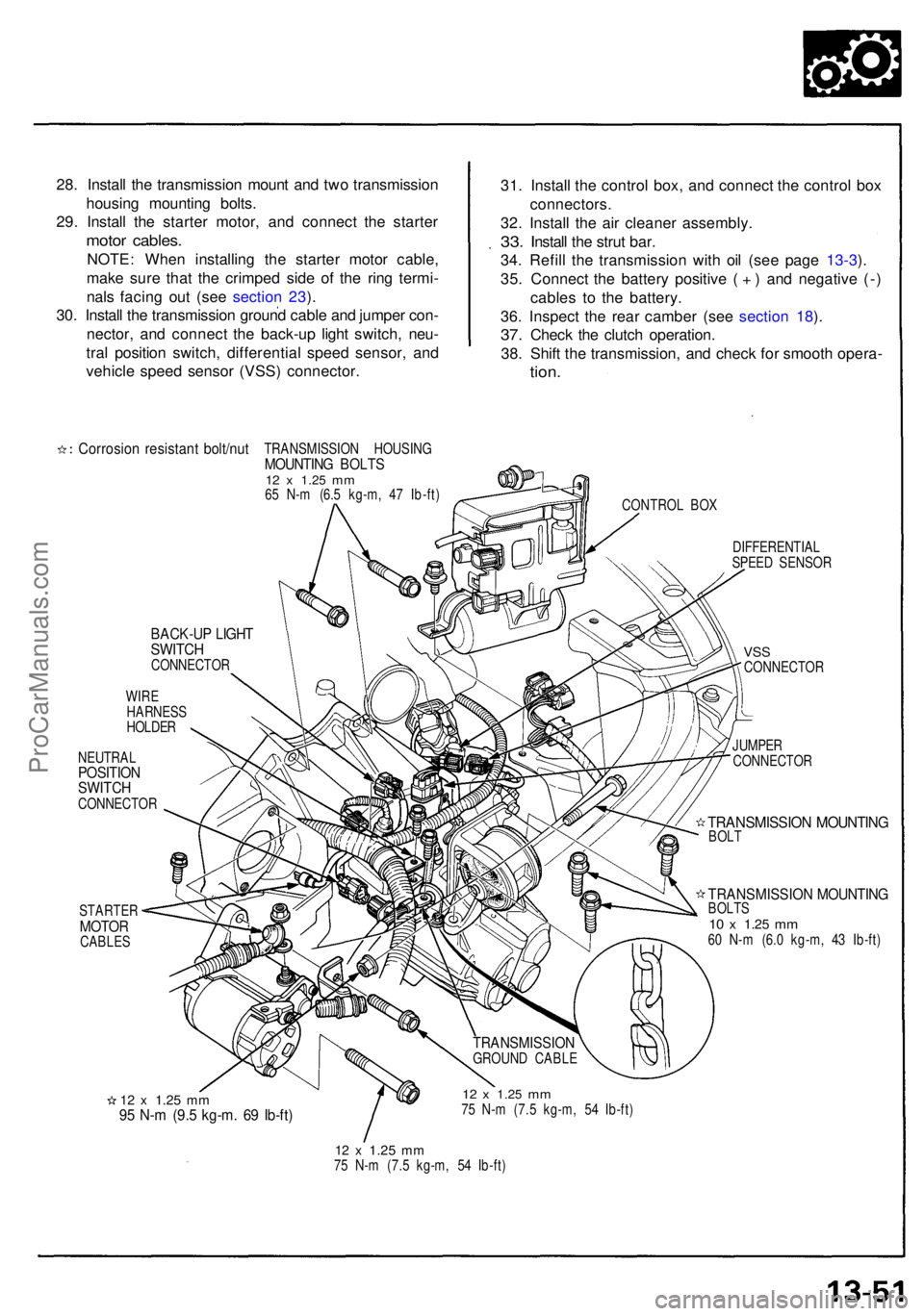
28. Instal l th e transmissio n moun t an d tw o transmissio n
housin g mountin g bolts .
29 . Instal l th e starte r motor , an d connec t th e starte r
motor cables .
NOTE: Whe n installin g th e starte r moto r cable ,
mak e sur e tha t th e crimpe d sid e o f th e rin g termi -
nal s facin g ou t (se e sectio n 23 ).
30 . Instal l th e transmissio n groun d cabl e an d jumpe r con -
nector , an d connec t th e back-u p ligh t switch , neu -
tra l positio n switch , differentia l spee d sensor , an d
vehicl e spee d senso r (VSS ) connector . 31
. Instal l th e contro l box , an d connec t th e contro l bo x
connectors .
32. Instal l th e ai r cleane r assembly .
33. Instal l th e stru t bar .
34 . Refil l th e transmissio n wit h oi l (se e pag e 13-3 ).
35 . Connec t th e batter y positiv e ( + ) an d negativ e (- )
cable s t o th e battery .
36 . Inspec t th e rea r cambe r (se e sectio n 18 ).
37 . Chec k th e clutc h operation .
38 . Shif t th e transmission , an d chec k fo r smoot h opera -
tion.
Corrosio n resistan t bolt/nu tTRANSMISSIO N HOUSIN GMOUNTING BOLT S12 x 1.2 5 mm65 N- m (6. 5 kg-m , 4 7 Ib-ft )
CONTROL BO X
BACK-U P LIGH TSWITC HCONNECTO R
WIR E
HARNES S
HOLDE R
NEUTRA L
POSITIONSWITCHCONNECTO R
STARTE R
MOTORCABLE S DIFFERENTIA
L
SPEE D SENSO R
VSSCONNECTO R
JUMPE R
CONNECTO R
TRANSMISSIO N MOUNTIN GBOLT
TRANSMISSIO N MOUNTIN GBOLTS10 x 1.2 5 mm60 N- m (6. 0 kg-m , 4 3 Ib-ft )
12 x 1.2 5 mm95 N- m (9. 5 kg-m . 6 9 Ib-ft )
12 x 1.2 5 mm75 N- m (7. 5 kg-m , 5 4 Ib-ft )
12 x 1.2 5 mm75 N- m (7. 5 kg-m , 5 4 Ib-ft )
TRANSMISSIO NGROUND CABL E
ProCarManuals.com
Page 531 of 1640
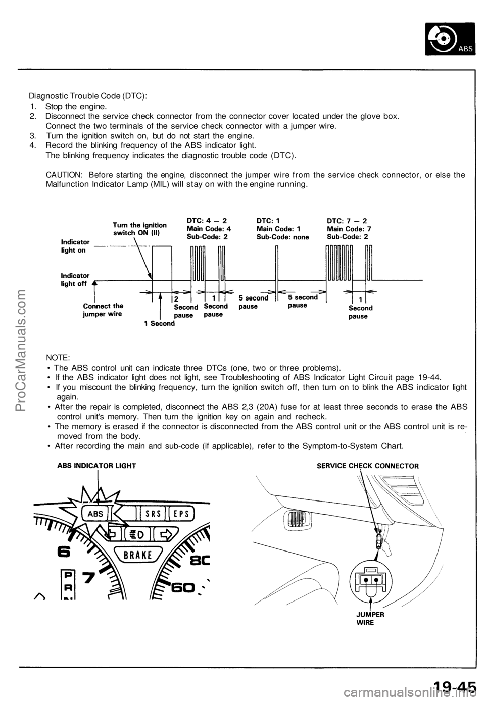
Diagnostic Trouble Code (DTC):
1. Stop the engine.
2. Disconnect the service check connector from the connector cover located under the glove box.
Connect the two terminals of the service check connector with a jumper wire.
3. Turn the ignition switch on, but do not start the engine.
4. Record the blinking frequency of the ABS indicator light.
The blinking frequency indicates the diagnostic trouble code (DTC).
CAUTION: Before starting the engine, disconnect the jumper wire from the service check connector, or else the
Malfunction Indicator Lamp (MIL) will stay on with the engine running.
NOTE:
• The ABS control unit can indicate three DTCs (one, two or three problems).
• If the ABS indicator light does not light, see Troubleshooting of ABS Indicator Light Circuit page 19-44.
• If you miscount the blinking frequency, turn the ignition switch off, then turn on to blink the ABS indicator light
again.
• After the repair is completed, disconnect the ABS 2,3 (20A) fuse for at least three seconds to erase the ABS
control unit's memory. Then turn the ignition key on again and recheck.
• The memory is erased if the connector is disconnected from the ABS control unit or the ABS control unit is re-
moved from the body.
• After recording the main and sub-code (if applicable), refer to the Symptom-to-System Chart.ProCarManuals.com
Page 748 of 1640
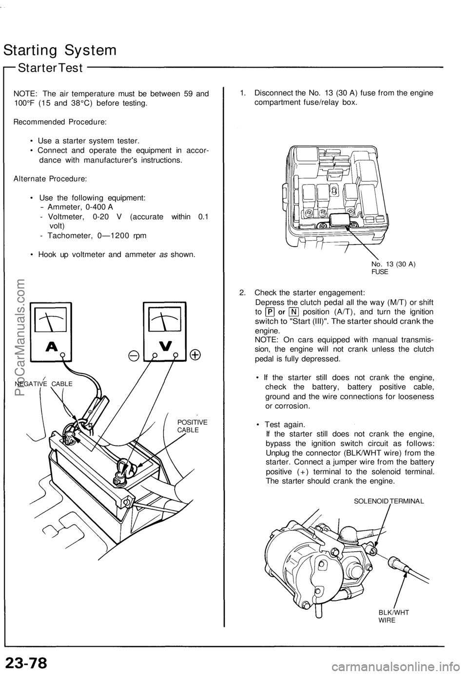
Starting Syste m
Starter Tes t
NOTE : Th e ai r temperatur e mus t b e betwee n 5 9 an d
100° F (1 5 an d 38°C ) befor e testing .
Recommende d Procedure :
• Us e a starte r syste m tester .
• Connec t an d operat e th e equipmen t i n accor -
danc e wit h manufacturer' s instructions .
Alternate Procedure :
• Us e th e followin g equipment :
- Ammeter, 0-400 A
- Voltmeter , 0-2 0 V (accurat e withi n 0. 1
volt )
- Tachometer , 0—120 0 rp m
• Hoo k u p voltmete r an d ammete r as shown .
NEGATIV E CABL E
POSITIV ECABLE
1. Disconnec t th e No . 1 3 (3 0 A ) fus e fro m th e engin e
compartmen t fuse/rela y box .
No. 1 3 (3 0 A )FUS E
2. Chec k th e starte r engagement :
Depres s th e clutc h peda l al l th e wa y (M/T ) o r shif t
to positio n (A/T) , an d tur n th e ignitio n
switch to "Star t (III)" . Th e starte r shoul d cran k th e
engine .
NOTE : O n car s equippe d wit h manua l transmis -
sion , th e engin e wil l no t cran k unles s th e clutc h
peda l i s full y depressed .
• I f th e starte r stil l doe s no t cran k th e engine ,
chec k th e battery , batter y positiv e cable ,
groun d an d th e wir e connection s fo r loosenes s
o r corrosion .
• Tes t again .
I f th e starte r stil l doe s no t cran k th e engine ,
bypas s th e ignitio n switc h circui t a s follows :
Unplu g th e connecto r (BLK/WH T wire ) fro m th e
starter . Connec t a jumpe r wir e fro m th e batter y
positiv e (+ ) termina l t o th e solenoi d terminal .
Th e starte r shoul d cran k th e engine .
SOLENOI D TERMINA L
BLK/WHTWIRE
ProCarManuals.com
Page 769 of 1640
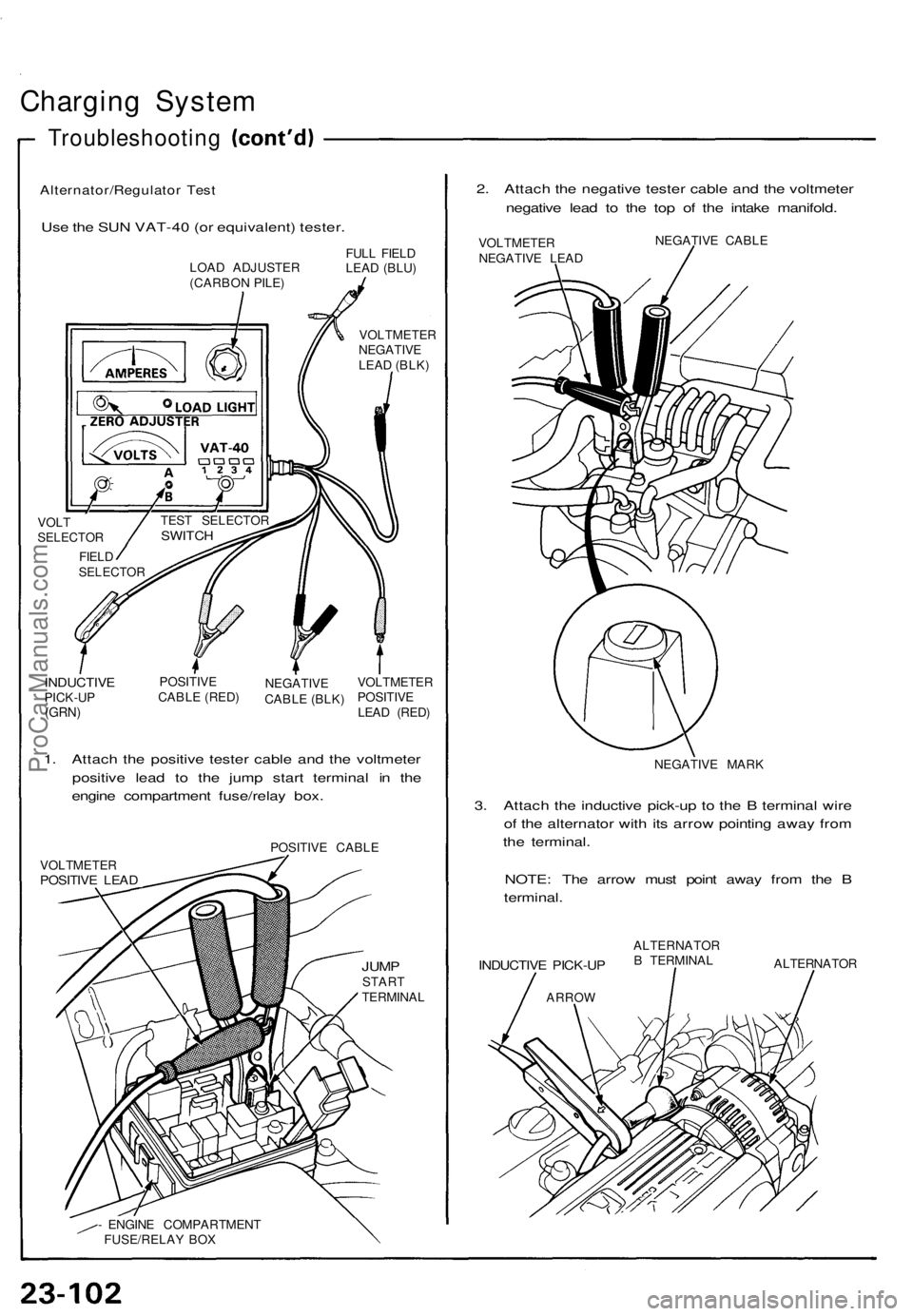
Charging System
Troubleshooting
Alternator/Regulator Test
Use the SUN VAT-40 (or equivalent) tester.
2. Attach the negative tester cable and the voltmeter
negative lead to the top of the intake manifold.
LOAD ADJUSTER
(CARBON PILE)
FULL FIELD
LEAD (BLU)
VOLTMETER
NEGATIVE
LEAD (BLK)
VOLT
SELECTOR
FIELD
SELECTOR
INDUCTIVE
PICK-UP
(GRN)
POSITIVE
CABLE (RED)
NEGATIVE
CABLE (BLK)
VOLTMETER
POSITIVE
LEAD (RED)
1. Attach the positive tester cable and the voltmeter
positive lead to the jump start terminal in the
engine compartment fuse/relay box.
POSITIVE CABLE
VOLTMETER
POSITIVE LEAD
JUMP
START
TERMINAL
- ENGINE COMPARTMENT
FUSE/RELAY BOX
VOLTMETER
NEGATIVE LEAD
NEGATIVE CABLE
NEGATIVE MARK
3. Attach the inductive pick-up to the B terminal wire
of the alternator with its arrow pointing away from
the terminal.
NOTE: The arrow must point away from the B
terminal.
INDUCTIVE PICK-UP
ARROW
ALTERNATOR
B TERMINAL
ALTERNATOR
TEST SELECTOR
SWITCHProCarManuals.com
Page 1148 of 1640
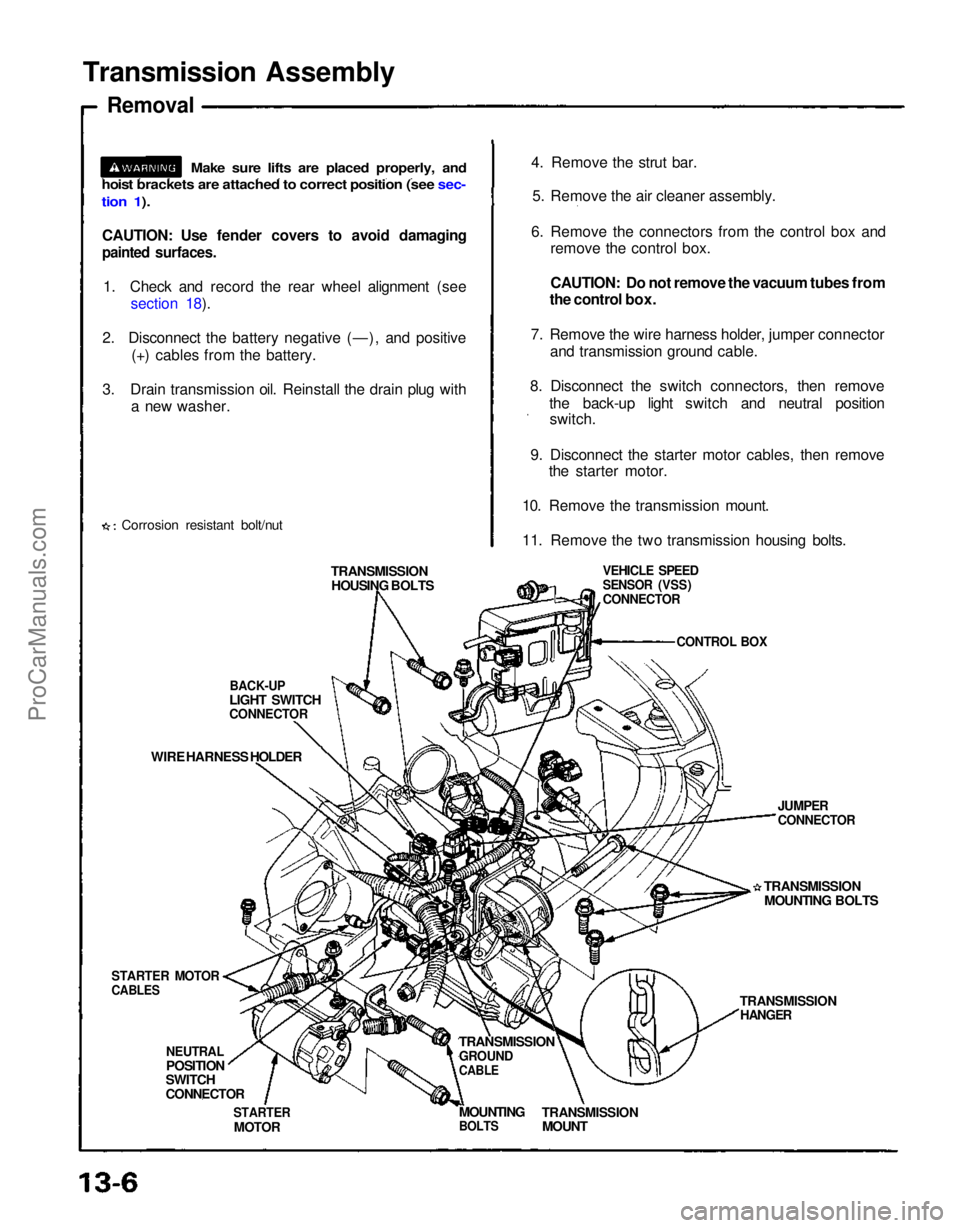
Transmission Assembly
Removal
CAUTION: Use fender covers to avoid damaging
painted surfaces.
1. Check and record the rear wheel alignment (see section 18).
2. Disconnect the battery negative (—), and positive (+) cables from the battery.
3. Drain transmission oil. Reinstall the drain plug with a new washer.
Corrosion resistant bolt/nut 4. Remove the strut bar.
5. Remove the air cleaner assembly.
6. Remove the connectors from the control box and remove the control box.
CAUTION: Do not remove the vacuum tubes from
the control box.
7. Remove the wire harness holder, jumper connector and transmission ground cable.
8. Disconnect the switch connectors, then remove the back-up light switch and neutral positionswitch.
9. Disconnect the starter motor cables, then remove the starter motor.
10. Remove the transmission mount.
11. Remove the two transmission housing bolts.
TRANSMISSION HOUSING BOLTS
BACK-UP
LIGHT SWITCH
CONNECTOR
WIRE HARNESS HOLDER
STARTER MOTOR
CABLES
NEUTRAL
POSITION
SWITCH
CONNECTOR
STARTER
MOTOR
TRANSMISSION
GROUND
CABLE
TRANSMISSION
MOUNT
MOUNTING
BOLTS
TRANSMISSION
HANGER
TRANSMISSION
MOUNTING BOLTS
JUMPER
CONNECTOR
VEHICLE SPEED
SENSOR (VSS)
CONNECTOR
CONTROL BOX
Make sure lifts are placed properly, and
hoist brackets are attached to correct position (see sec-
tion 1).ProCarManuals.com
Page 1163 of 1640
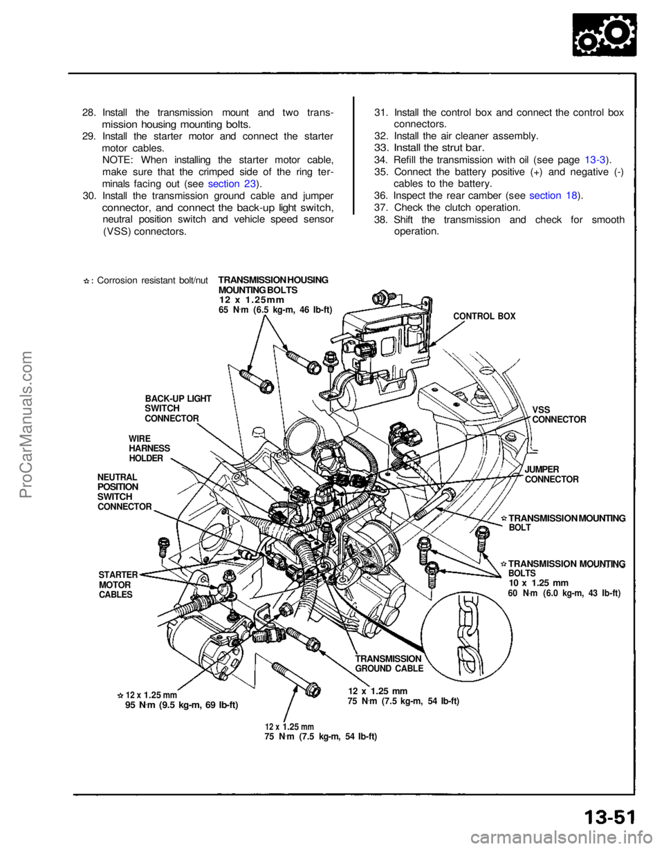
28. Install the transmission mount and two trans-
mission housing mounting bolts.
29. Install the starter motor and connect the starter
motor cables.NOTE: When installing the starter motor cable,
make sure that the crimped side of the ring ter-
minals facing out (see section 23).
30. Install the transmission ground cable and jumper
connector, and connect the back-up light switch,
neutral position switch and vehicle speed sensor
(VSS) connectors.
Corrosion resistant bolt/nut
TRANSMISSION HOUSING
MOUNTING BOLTS12 x 1.25mm
65 N
.
m (6.5 kg-m, 46 Ib-ft)
BACK-UP LIGHT
SWITCH
CONNECTOR
WIRE
HARNESS
HOLDER
NEUTRAL
POSITION
SWITCH
CONNECTOR
STARTER
MOTOR
CABLES
12 x
1.25
mm
95 N
.
m (9.5 kg-m, 69 Ib-ft)
12 x
1.25
mm
75 N
.
m (7.5 kg-m, 54 Ib-ft)
12 x
1.25
mm
75 N .
m (7.5 kg-m, 54 Ib-ft)
TRANSMISSION
GROUND CABLE
TRANSMISSION MOUNTING
BOLTS
10 x
1.25
mm
60 N .
m (6.0 kg-m, 43 Ib-ft)
JUMPER
CONNECTOR
VSS
CONNECTOR
CONTROL BOX
31. Install the control box and connect the control box
connectors.
32. Install the air cleaner assembly.
33. Install the strut bar.
34. Refill the transmission with oil (see page 13-3).
35. Connect the battery positive (+) and negative (-) cables to the battery.
36. Inspect the rear camber (see section 18).
37. Check the clutch operation.
38. Shift the transmission and check for smooth operation.
TRANSMISSION MOUNTING
BOLTProCarManuals.com
Page 1539 of 1640
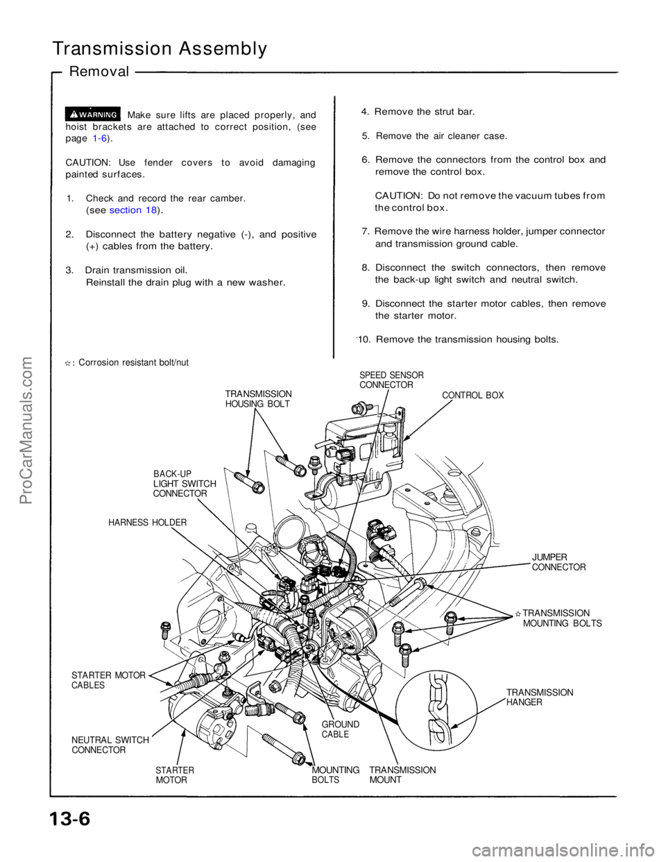
Transmission Assembly
Removal
Make sure lifts are placed properly, and
hoist brackets are attached to correct position, (see
page 1-6).
CAUTION: Use fender covers to avoid damaging
painted surfaces.
1. Check and record the rear camber.
(see section 18).
2. Disconnect the battery negative (-), and positive (+) cables from the battery.
3. Drain transmission oil. Reinstall the drain plug with a new washer.
Corrosion resistant bolt/nut
TRANSMISSION
HOUSING BOLT
BACK-UP
LIGHT SWITCH
CONNECTOR
HARNESS HOLDER
STARTER MOTOR
CABLES
NEUTRAL SWITCH
CONNECTOR
STARTER
MOTOR
MOUNTING
BOLTS
TRANSMISSION
MOUNT
GROUND
CABLE
TRANSMISSION
HANGER
TRANSMISSION
MOUNTING BOLTS
JUMPER
CONNECTOR
CONTROL BOX
SPEED SENSOR
CONNECTOR
4. Remove the strut bar.
5. Remove the air cleaner case.
6. Remove the connectors from the control box and remove the control box.
CAUTION: Do not remove the vacuum tubes from
the control box.
7. Remove the wire harness holder, jumper connector and transmission ground cable.
8. Disconnect the switch connectors, then remove the back-up light switch and neutral switch.
9. Disconnect the starter motor cables, then remove the starter motor.
10. Remove the transmission housing bolts.ProCarManuals.com