1991 ACURA NSX parking brake
[x] Cancel search: parking brakePage 306 of 1640
Transmission Assembly
Removal
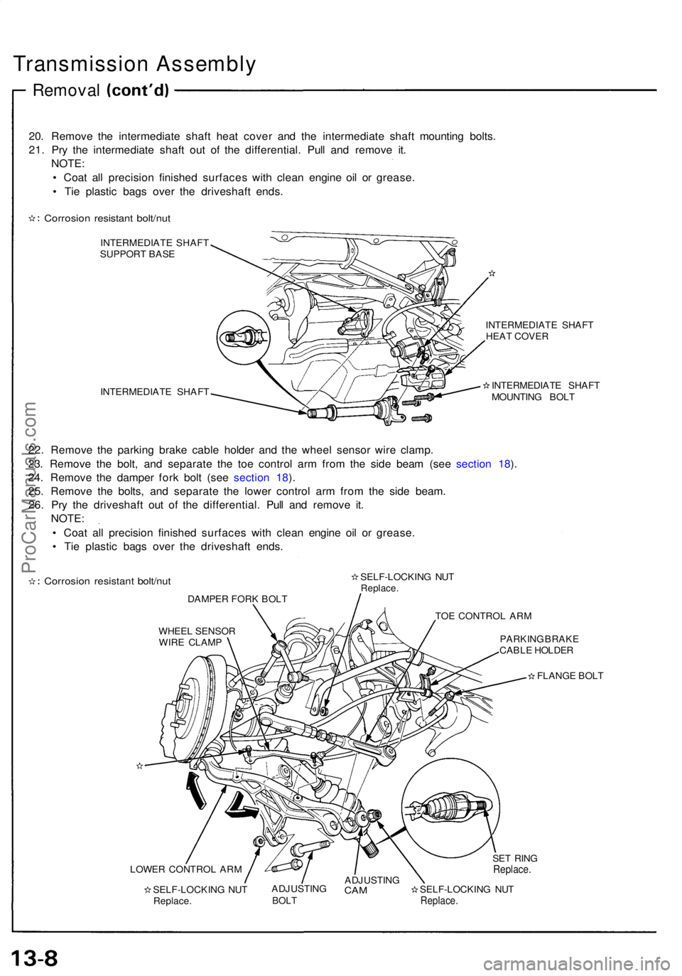
20. Remove the intermediate shaft heat cover and the intermediate shaft mounting bolts.
21. Pry the intermediate shaft out of the differential. Pull and remove it. NOTE:
• Coat all precision finished surfaces with clean engine oil or grease.
• Tie plastic bags over the driveshaft ends.
Corrosion resistant bolt/nut
INTERMEDIATE SHAFT
SUPPORT BASE
INTERMEDIATE SHAFT INTERMEDIATE SHAFT
HEAT COVER
INTERMEDIATE SHAFT
MOUNTING BOLT
22. Remove the parking brake cable holder and the wheel sensor wire clamp.
23. Remove the bolt, and separate the toe control arm from the side beam (see section 18).
24. Remove the damper fork bolt (see section 18).
25. Remove the bolts, and separate the lower control arm from the side beam. 26. Pry the driveshaft out of the differential. Pull and remove it. NOTE:
• Coat all precision finished surfaces with clean engine oil or grease.
• Tie plastic bags over the driveshaft ends.
Corrosion resistant bolt/nut
DAMPER FORK BOLT SELF-LOCKING NUT
Replace.
TOE CONTROL ARM
WHEEL SENSOR WIRE CLAMP PARKING BRAKE
CABLE HOLDER
FLANGE BOLT
LOWER CONTROL ARM SELF-LOCKING NUTReplace. ADJUSTING
BOLT
ADJUSTING
CAM
SELF-LOCKING NUT
Replace.
SET RING
Replace.ProCarManuals.com
Page 493 of 1640
Pedal Heigh t
Adjustmen t
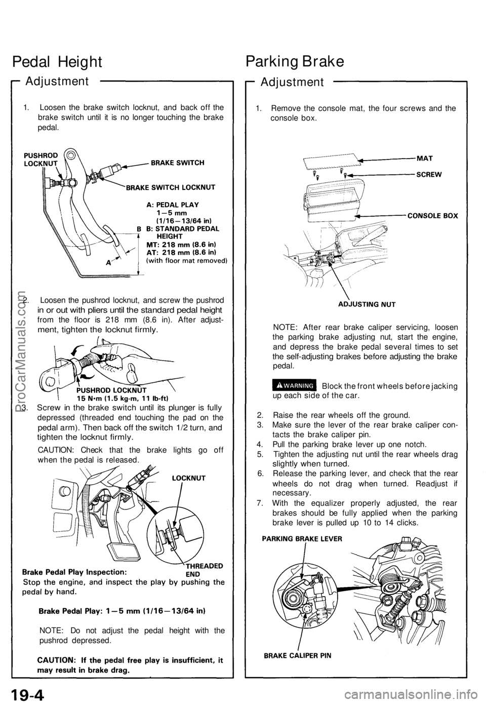
1. Loose n th e brak e switc h locknut , an d bac k of f th e
brak e switc h unti l i t i s n o longe r touchin g th e brak e
pedal .
2 . Loose n th e pushro d locknut , an d scre w th e pushro d
in o r ou t wit h plier s unti l th e standar d peda l heigh t
from th e floo r i s 21 8 m m (8. 6 in) . Afte r adjust -
ment, tighte n th e locknu t firmly .
3. Scre w in th e brak e switc h unti l it s plunge r i s full y
depresse d (threade d en d touchin g th e pa d o n th e
peda l arm) . The n bac k of f th e switc h 1/ 2 turn , an d
tighte n th e locknu t firmly .
CAUTION : Chec k tha t th e brak e light s g o of f
whe n th e peda l i s released .
NOTE : D o no t adjus t th e peda l heigh t wit h th e
pushro d depressed .
Parking Brak e
Adjustmen t
1. Remov e th e consol e mat , th e fou r screw s an d th e
consol e box .
NOTE : Afte r rea r brak e calipe r servicing , loose n
th e parkin g brak e adjustin g nut , star t th e engine ,
an d depres s th e brak e peda l severa l time s t o se t
the self-adjustin g brake s befor e adjustin g th e brak e
pedal .
Block th e fron t wheel s befor e jackin g
u p eac h sid e o f th e car .
2 . Rais e th e rea r wheel s of f th e ground .
3 . Mak e sur e th e leve r o f th e rea r brak e calipe r con -
tact s th e brak e calipe r pin .
4 . Pul l th e parkin g brak e leve r u p on e notch .
5 . Tighte n th e adjustin g nu t unti l th e rea r wheel s dra g
slightl y whe n turned .
6. Releas e th e parkin g lever , an d chec k tha t th e rea r
wheel s d o no t dra g whe n turned . Readjus t i f
necessary .
7. Wit h th e equalize r properl y adjusted , th e rea r
brake s shoul d b e full y applie d whe n th e parkin g
brak e leve r i s pulle d u p 1 0 t o 1 4 clicks .
ProCarManuals.com
Page 521 of 1640
Anti-lock Brake System (ABS) Description
Features/Construction/Operation (cont'd)
ABS Control Unit
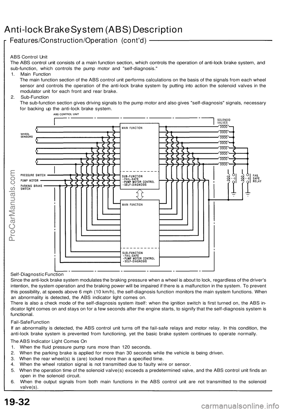
The ABS control unit consists of a main function section, which controls the operation of anti-lock brake system, and
sub-function, which controls the pump motor and "self-diagnosis."
1. Main Function
The main function section of the ABS control unit performs calculations on the basis of the signals from each wheel
sensor and controls the operation of the anti-lock brake system by putting into action the solenoid valves in the
modulator unit for each front and rear brake.
2. Sub-Function
The sub-function section gives driving signals to the pump motor and also gives "self-diagnosis" signals, necessary
for backing up the anti-lock brake system.
Self-Diagnostic Function
Since the anti-lock brake system modulates the braking pressure when a wheel is about to lock, regardless of the driver's
intention, the system operation and the braking power will be impaired if there is a malfunction in the system. To prevent
this possibility, at speeds above 6 mph (10 km/h), the self-diagnosis function monitors the main system functions. When
an abnormality is detected, the ABS indicator light comes on.
There is also a check mode of the self-diagnosis system itself: when the ignition switch is first turned on, the ABS in-
dicator light comes on and stays on for a few seconds after the engine starts, to signify that the self-diagnosis system is
functional.
Fail-Safe Function
If an abnormality is detected, the ABS control unit turns off the fail-safe relays and motor relay. In this condition, the
anti-lock brake system is prevented from functioning, yet the basic brake system continues to operate normally.
The ABS Indicator Light Comes On
1. When the fluid pressure pump runs more than 120 seconds.
2. When the parking brake is applied for more than 30 seconds while the vehicle is being driven.
3. When the rear wheel(s) is (are) locked more than a specified time.
4. When the wheel rotation signal is not transmitted due to faulty wire or sensor.
5. When the operation time of the solenoid valve(s) exceeds a predetermined valve, and the ABS control unit finds an
open in the solenoid circuit.
6. When the output signals from both main functions in the ABS control unit are not transmitted to the solenoid
valve(s).ProCarManuals.com
Page 609 of 1640
Dashboard
Component Removal/Installation (cont'd)
SRS components are located in this area. Review the SRS component locations, precautions, and procedures in the SRS
section (24) before performing repairs or service.
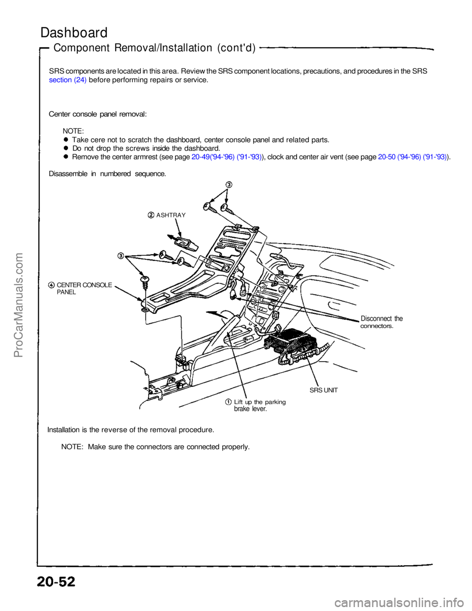
Center console panel removal:
NOTE:
Take cere not to scratch the dashboard, center console panel and related parts.Do not drop the screws inside the dashboard.
Remove the center armrest (see page 20-49('94-'96) ('91-'93)), clock and center air vent (see page 20-50 ('94-'96) ('91-'93)).
Disassemble in numbered sequence.
ASHTRAY
CENTER CONSOLE
PANEL
Disconnect the
connectors.
Lift up the parking
brake lever.
SRS UNIT
Installation is the reverse of the removal procedure. NOTE: Make sure the connectors are connected properly.ProCarManuals.com
Page 799 of 1640
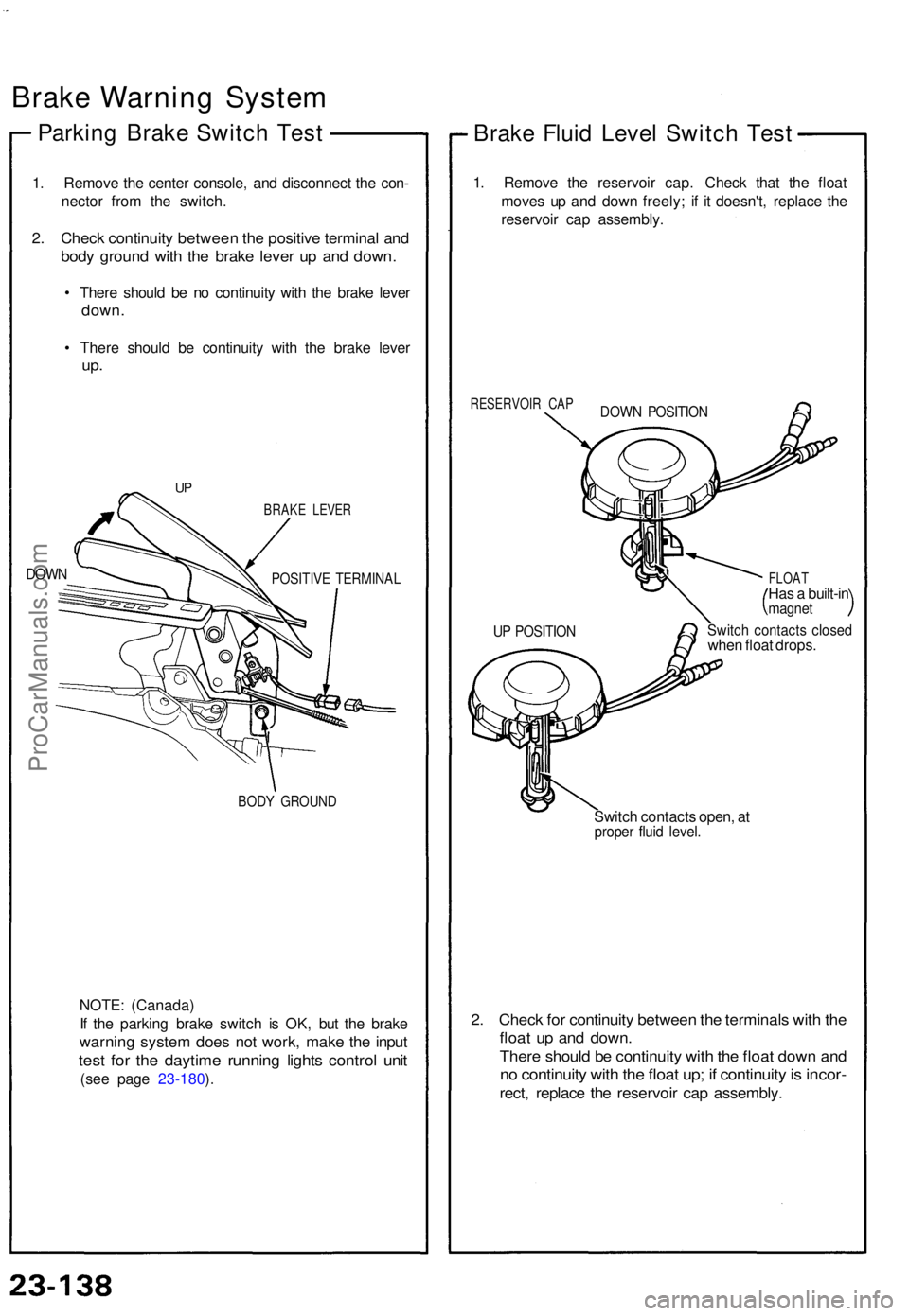
Brake Warnin g Syste m
Parking Brak e Switc h Tes t
1. Remov e th e cente r console , an d disconnec t th e con -
necto r fro m th e switch .
2. Chec k continuit y betwee n th e positiv e termina l an d
bod y groun d wit h th e brak e leve r u p an d down .
• Ther e shoul d b e n o continuit y wit h th e brak e leve r
down .
• Ther e shoul d b e continuit y wit h th e brak e leve r
up.
DOW N
BRAK E LEVE R
POSITIV E TERMINA L
BODY GROUN D
NOTE: (Canada )
I f th e parkin g brak e switc h i s OK , bu t th e brak e
warnin g syste m doe s no t work , mak e th e inpu t
test fo r th e daytim e runnin g light s contro l uni t
(see pag e 23-180 ).
Brak e Flui d Leve l Switc h Tes t
1. Remov e th e reservoi r cap . Chec k tha t th e floa t
move s u p an d dow n freely ; i f i t doesn't , replac e th e
reservoi r ca p assembly .
RESERVOI R CA P
FLOAT
Has a built-i nmagne t
Switch contact s close dwhen floa t drops .
Switc h contact s open , a t
prope r flui d level .
2. Chec k fo r continuit y betwee n th e terminal s wit h th e
floa t u p an d down .
There shoul d b e continuit y wit h th e floa t dow n an d
no continuit y wit h th e floa t up ; i f continuit y is incor -
rect, replac e th e reservoi r ca p assembly .
UP POSITIO N
DOWN POSITIO N
UP
ProCarManuals.com
Page 973 of 1640
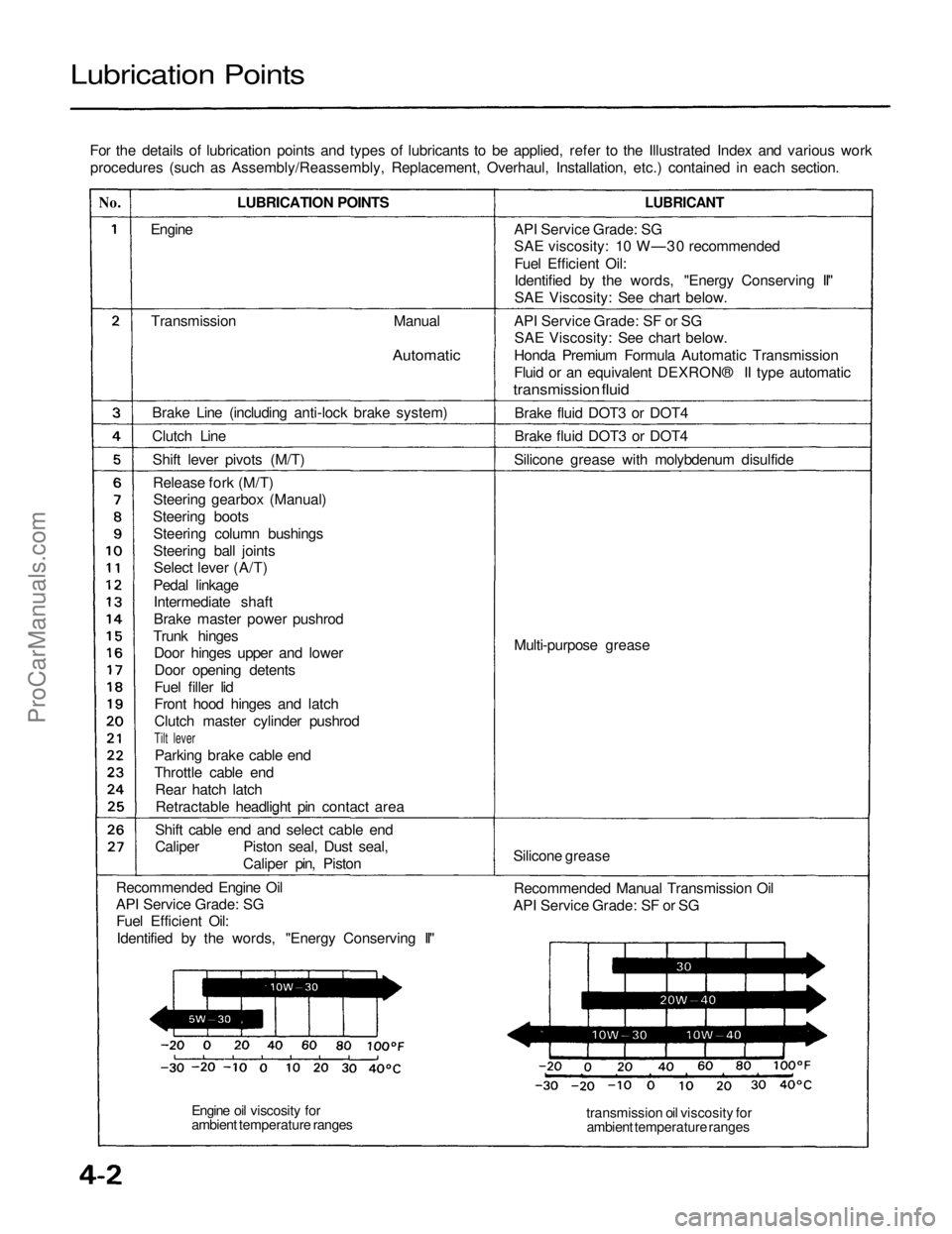
Lubrication Points
For the details of lubrication points and types of lubricants to be applied, refer to the Illustrated Index and various workprocedures (such as Assembly/Reassembly, Replacement, Overhaul, Installation, etc.) contained in each section.
No.
LUBRICATION POINTS
LUBRICANT
Engine
Transmission
Manual
Automatic
Brake Line (including anti-lock brake system)
Clutch Line Shift lever pivots (M/T)Release fork (M/T)Steering gearbox (Manual)
Steering boots Steering column bushings
Steering ball jointsSelect lever (A/T)
Pedal linkage Intermediate shaft
Brake master power pushrod
Trunk hinges Door hinges upper and lower
Door opening detents
Fuel filler lid
Front hood hinges and latch
Clutch master cylinder pushrod
Tilt lever
Parking brake cable end
Throttle cable end Rear hatch latchRetractable headlight pin contact area
Shift cable end and select cable end
Caliper Piston seal, Dust seal, Caliper pin, Piston
Recommended Engine Oil
API Service Grade: SG Fuel Efficient Oil:
Identified by the words, "Energy Conserving II" API Service Grade: SG
SAE viscosity: 10 W—30 recommended
Fuel Efficient Oil:
Identified by the words, "Energy Conserving II"
SAE Viscosity: See chart below.
API Service Grade: SF or SG SAE Viscosity: See chart below.
Honda Premium Formula Automatic Transmission
Fluid or an equivalent DEXRON® II type automatic
transmission fluid
Brake fluid DOT3 or DOT4
Brake fluid DOT3 or DOT4
Silicone grease with molybdenum disulfide
Multi-purpose grease
Silicone grease Recommended Manual Transmission Oil
API Service Grade: SF or SG
transmission oil viscosity forambient temperature ranges
Engine oil viscosity for
ambient temperature rangesProCarManuals.com
Page 991 of 1640
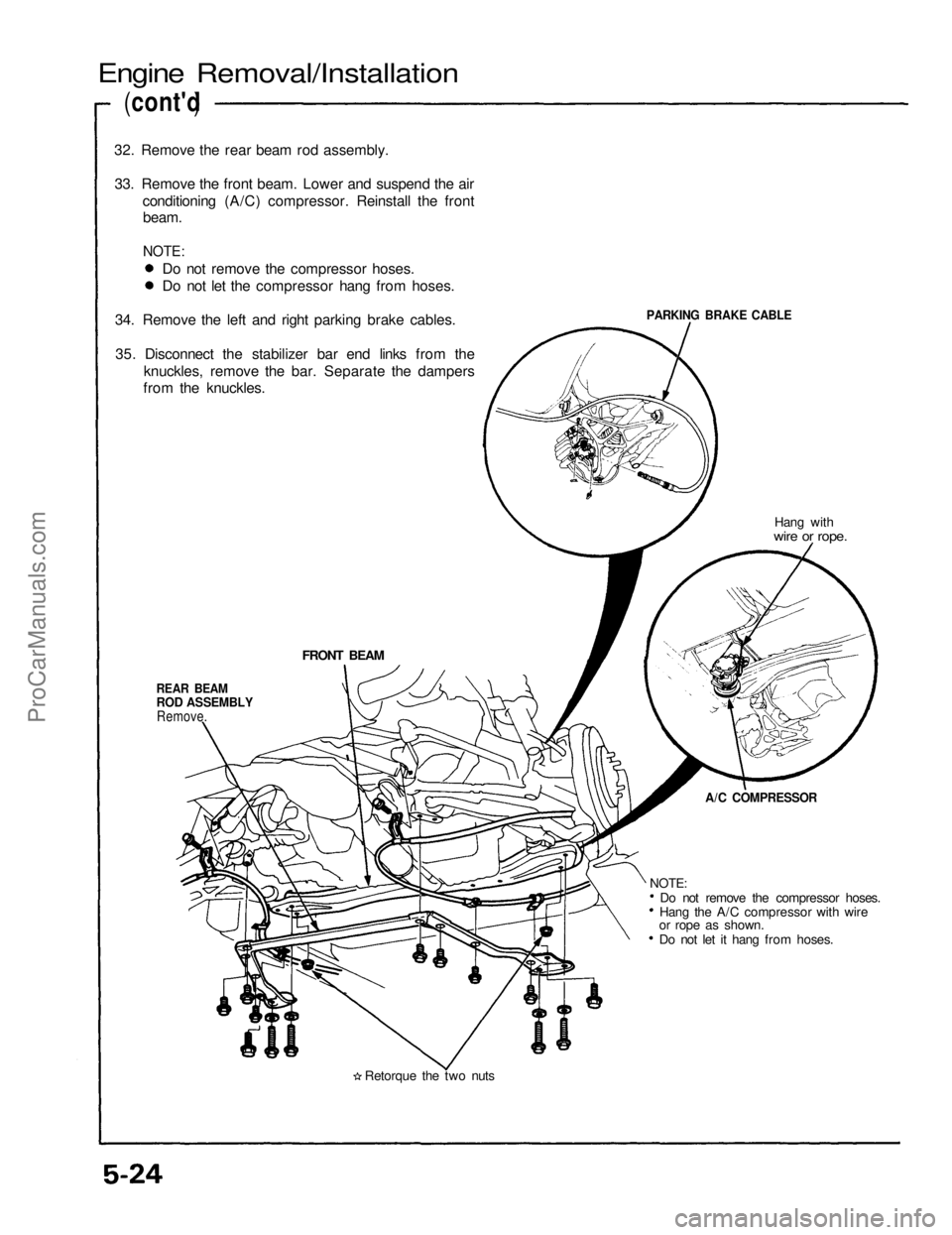
Engine Removal/Installation
(cont'd )
32. Remove the rear beam rod assembly.
33. Remove the front beam. Lower and suspend the air conditioning (A/C) compressor. Reinstall the frontbeam.
NOTE:
PARKING BRAKE CABLE
Hang with
wire or rope.
FRONT BEAM
REAR BEAM
ROD ASSEMBLY
Remove.
A/C COMPRESSOR
Do not remove the compressor hoses.
Hang the A/C compressor with wire
or rope as shown.
Do not let it hang from hoses.
Retorque the two nuts
NOTE:
Do not remove the compressor hoses.
Do not let the compressor hang from hoses.
34. Remove the left and right parking brake cables.
35. Disconnect the stabilizer bar end links from the knuckles, remove the bar. Separate the dampers
from the knuckles.ProCarManuals.com
Page 1106 of 1640
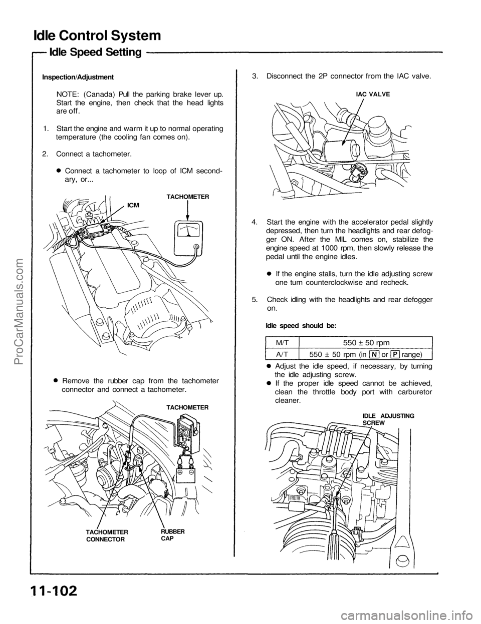
Idle Control System
Idle Speed Setting
Inspection/Adjustment NOTE: (Canada) Pull the parking brake lever up.
Start the engine, then check that the head lights
are
off.
1. Start the engine and warm it up to normal operating temperature (the cooling fan comes on).
2. Connect a tachometer. Connect a tachometer to loop of ICM second-
ary, or...
TACHOMETER
ICM
Remove the rubber cap from the tachometer
connector and connect a tachometer.
TACHOMETER
TACHOMETER CONNECTOR
RUBBER
CAP
3. Disconnect the 2P connector from the IAC valve.
IAC VALVE
4. Start the engine with the accelerator pedal slightly depressed, then turn the headlights and rear defog-
ger ON. After the MIL comes on, stabilize the
engine speed at 1000 rpm, then slowly release the
pedal until the engine idles.
If the engine stalls, turn the idle adjusting screw
one turn counterclockwise and recheck.
5. Check idling with the headlights and rear defogger
on.
Idle speed should be:
M/T
A/T
550 ± 50 rpm
550 ± 50 rpm (in or range)
Adjust the idle speed, if necessary, by turning
the idle adjusting screw.
If the proper idle speed cannot be achieved,
clean the throttle body port with carburetor
cleaner.
IDLE ADJUSTING
SCREWProCarManuals.com