1991 ACURA NSX coolant temperature
[x] Cancel search: coolant temperaturePage 97 of 1640
![ACURA NSX 1991 Service Repair Manual
Cylinder Heads
Illustrated Index (cont'd)
CAUTION:
To
avoid
damage,
wait
until
the
engine
coolant
temperature
drops
below
100°F
(39-C]
before
removing
the
cylin-
der head.
N ACURA NSX 1991 Service Repair Manual
Cylinder Heads
Illustrated Index (cont'd)
CAUTION:
To
avoid
damage,
wait
until
the
engine
coolant
temperature
drops
below
100°F
(39-C]
before
removing
the
cylin-
der head.
N](/manual-img/32/56988/w960_56988-96.png)
Cylinder Heads
Illustrated Index (cont'd)
CAUTION:
To
avoid
damage,
wait
until
the
engine
coolant
temperature
drops
below
100°F
(39-C]
before
removing
the
cylin-
der head.
NOTE: Use new O-rings and gaskets when reassembling.
Prior to reassembling, clean all the parts in solvent, dry them, and apply lubricant to any contact parts.
REAR VARIABLE VALVE TIMING
AND VALVE LIFT ELECTRONIC CONTROL
SYSTEM (VTEC) SOLENOID VALVE
Troubleshooting, page 6-3 ('91-'93) or ('94-'96)
EXHAUST GAS
RECIRCULATI0N (EGR) VALVE
6 x 1 .0 mm
12 N·m
(1.2 kg-m.
9 Ib-ft)
8 x
1.25
mm
22 N·m
(2.2 kg-m,
16 Ib-ft)
ENGINE COOLANT
TEMPERATURE (ECT) SENSOR
18 N·m (1.8 kg-m, 13 Ib-ft)
8 x
1.25
mm
22 N·m (2.2 kg-m. 16 lb-ft)
FRONT VTEC SOLENOID VALVE
Troubleshooting. page 6-3
SEALING BOLTS
60 N·m
(6.0 kg-m,
43 lb-ft)
OIL PRESSURE
GAUSE SENDING
UNIT (section 23)
ROCKER
SHAFTS
WASHERS
Replace.
8 x
1.25
mm
22 N·m
(2.2 kg-m,16 Ib-ft)
DOWEL PIN
0-RING
Replace.
ECT SWITCH
28 N·m
12.8 kg-m.
20 lb-ft
O-RING
Replace.
O-RING
Replace.
ROCKER ARM ASSEMBLY[PRIMARY. MID, SECONDARY]
Inspection, page 6-32 ('91-'93) or ('94-'96)
ROCKER SHAFT
OIL CONTROL
ORIFICE
Remove with 5 mm
boit and clean.
FILTER
Replace.
GASKET
Replace.
O-RING
Replace.ProCarManuals.com
Page 99 of 1640
Cylinder Heads
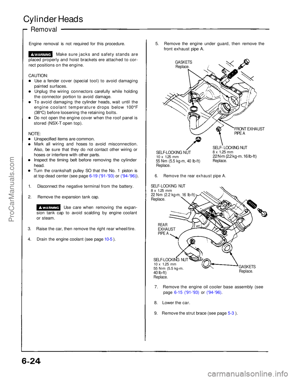
Removal
Engine removal is not required for this procedure. Make sure jacks and safety stands are
placed properly and hoist brackets ere attached to cor- rect positions on the engine.
CAUTION: Use a fender cover (special tool) to avoid damaging
painted surfaces. Unplug the wiring connectors carefully while holding
the connector portion to avoid damage.
To avoid damaging the cylinder heads, wait until the
engine coolant temperature drops below 100°F
(38°C) before loosening the retaining bolts. Do not open the engine cover when the roof panel is
stored (NSX-T open top).
NOTE:
Unspecified items are common.
Mark all wiring and hoses to avoid misconnection.
Also, be sure that they do not contact other wiring or
hoses or interfere with other parts.
Inspect the timing belt before removing the cylinder
head.
Turn the crankshaft pulley SO that the No. 1 piston is at top dead center (see page 6-19 ('91-'93) or ('94-'96)).
1. Disconnect the negative terminal from the battery.
2. Remove the expansion tank cap. Use care when removing the expan-
sion tank cap to avoid scalding by engine coolant
or steam.
3. Raise the car, then remove the right rear wheel/tire.
4. Drain the engine coolant (see page 10-5 ). 5. Remove the engine under guard, then remove the
front exhaust pipe A.
GASKETS
Replace.
FRONT EXHAUST
PIPE A
SELF-LOCKING NUT
10 x
1.25
mm
55 N·m (5.5 kg-m, 40 Ib-ft)
Replace.
SELF- LOCKING NUT
8 x
1.25
mm
22 N·m (2.2 kg-m. 16 Ib-ft)
Replace.
6. Remove the rear exhaust pipe A.
SELF- LOCKING NUT
8 x
1.25
mm
22 N·m (2.2 kg-m, 16 Ib-ft)
Replace.
REAR
EXHAUST
PIPE A
SELF-LOCKING NUT
10 x
1.25
mm
55 N·m (5.5 kg-m.
40 Ib-ft)
Replace.
GASKETS
Replace.
7. Remove the engine oil cooler base assembly (see
page 6-15 ('91-'93) or ('94-'96).
8. Lower the car.
9. Remove the strut brace (see page 5-3 ).ProCarManuals.com
Page 102 of 1640

24. Remove the engine wire harness connectors and
wire harness clamps from the cylinder head and
intake manifold, Six injector connectors
Intake air temperature (IAT) sensor connector
CKP/CYP sensor connector
Heated oxygen sensor (HO2S) connectors
Ignition control module (ICM) connectors
Engine coolant temperature (ECT) sensor connec-
tor
ECT gauge sending unit connector
ECT switch connector
Exhaust gas recirculation (EGR) valve lift sensor
connector
Throttle position sensor connector Engine oil pressure gauge sending unit connector
Knock sensor connector
VTEC solenoid valve connectors
VTEC pressure switch connectors
Engine oil pressure switch connector
Alternator connector
Alternator terminal
Throttle body 6P connector
25. Remove the ignition coils and connector.
26. Remove the EGR pipe and intake manifold assem- bly.
8 x 1.25mm
22 N·m (2.2 kg-m, 16 Ib-ft)
6 x 1.0 mm
12 N·m
(1.2 kg-m,
9 lb-ft)
GASKETS
Replace. INTAKE
MANIFOLD
ASSEMBLY
GASKET
Replace.
27. Loosen the adjusting nut and idler pulley center nut,
then remove the air conditioning compressor belt
(see page 6-17('91-'93) or ('94-'96)).
28. Remove the cover, adjusting bolt, mounting bolt and mounting nut, then remove the alternator belt
and alternator.
COVER
MOUNTING BOLT
10 x
1.25
mm
45 N·m (4.5 kg·m,
33 Ib-ft)
MOUNTING NUT
10 x
1.25
mm
45 N·m (4.5 kg·m.
33 Ib·ft)
ALTERNATOR
BELT
29. Disconnect the knock sensor connector, then remove
the wire holder.
6 x 1.0 mm
12N·m (1.2 kg-m, 9 Ib-ft)
KNOCK SENSOR
WIRE HOLDER
(cont'd)
6 x 1.0 mm
12 N·m (1.2 kg-m, 9 Ib-ft)
ADJUSTING
BOLTProCarManuals.com
Page 165 of 1640
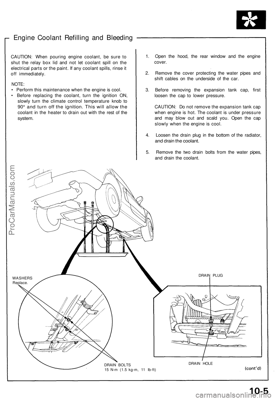
Engine Coolant Refilling and Bleeding
CAUTION: When pouring engine coolant, be sure to
shut the relay box lid and not let coolant spill on the
electrical parts or the paint. If any coolant spills, rinse it
off immediately.
NOTE:
• Perform this maintenance when the engine is cool.
• Before replacing the coolant, turn the ignition ON,
slowly turn the climate control temperature knob to
90° and turn off the ignition. This will allow the
coolant in the heater to drain out with the rest of the
system.
1. Open the hood, the rear window and the engine
cover.
2. Remove the cover protecting the water pipes and
shift cables on the underside of the car.
3. Before removing the expansion tank cap, first
loosen the cap to lower pressure.
CAUTION: Do not remove the expansion tank cap
when engine is hot. The coolant is under pressure
and may blow out and scald you. Open the cap
slowly when the engine is cool.
4. Loosen the drain plug in the bottom of the radiator,
and drain the coolant.
5. Remove the two drain bolts from the water pipes,
and drain the coolant.
WASHERS
Replace.
DRAIN BOLTS
15 N-m (1.5 kg-m, 11 Ib-ft)
DRAIN HOLE
DRAIN PLUGProCarManuals.com
Page 228 of 1640

PGM-FI System
System Description
PGM-FI System
The PGM-FI system on this model is a sequential multiport fuel injection system.
Fuel Injector Timing and Duration
The ECM contains memories for the basic discharge durations at various engine speeds and manifold pressures. The
basic discharge duration, after being read out from the memory, is further modified by signals sent from various sensors
to obtain the final discharge duration.
Throttle Valve Control
The ECM controls the throttle valve control motor based on accelerator pedal position, TCS control unit and various sig-
nals. The ECM also controls the idle control function, cruise control function, and other functions with the throttle valve
control.
Ignition Timing Control
• The ECM contains memories for basic ignition timing at various engine speeds and manifold pressures. Ignition timing
is also adjusted for engine coolant temperature.
• A knock control system is also used. When detonation is detected by the knock sensor (KS), the ignition timing is
retarded.
Other Control Functions
1. Starting Control
When the engine is started, the ECM provides a rich mixture by increasing fuel injector duration.
2. Fuel Pump Control
• When the ignition switch is initially turned on, the ECM supplies ground to the PGM-FI main relay that supplies
current to the fuel pump for two seconds to pressurize the fuel system.
• When the engine is running, the ECM supplies ground to the PGM-FI main relay that supplies current to the fuel pump.
• When the engine is not running and the ignition is on, the ECM cuts ground to the PGM-FI main relay which cuts
current to the fuel pump.
• Excellent engine performance is achieved through the use of VTEC (Variable Valve Timing and Valve Lift Electronic
Control System), intake air bypass control and discharge volume control of the fuel pump.ProCarManuals.com
Page 280 of 1640
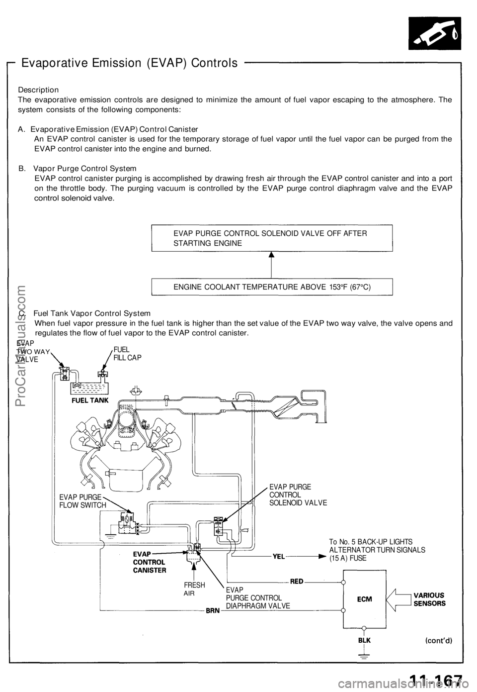
Evaporative Emission (EVAP) Controls
Description
The evaporative emission controls are designed to minimize the amount of fuel vapor escaping to the atmosphere. The
system consists of the following components:
A. Evaporative Emission (EVAP) Control Canister
An EVAP control canister is used for the temporary storage of fuel vapor until the fuel vapor can be purged from the
EVAP control canister into the engine and burned.
B. Vapor Purge Control System
EVAP control canister purging is accomplished by drawing fresh air through the EVAP control canister and into a port
on the throttle body. The purging vacuum is controlled by the EVAP purge control diaphragm valve and the EVAP
control solenoid valve.
EVAP PURGE CONTROL SOLENOID VALVE OFF AFTER
STARTING ENGINE
ENGINE COOLANT TEMPERATURE ABOVE 153°F (67°C)
To No. 5 BACK-UP LIGHTS
ALTERNATOR TURN SIGNALS
(15 A) FUSE
FRESH
AIR
EVAP
PURGE CONTROL
DIAPHRAGM VALVE
EVAP PURGE
CONTROL
SOLENOID VALVE
EVAP PURGE
FLOW SWITCH
C. Fuel Tank Vapor Control System
When fuel vapor pressure in the fuel tank is higher than the set value of the EVAP two way valve, the valve opens and
regulates the flow of fuel vapor to the EVAP control canister.
EVAP
TWO WAY
VALVE
FUEL
FILL CAPProCarManuals.com
Page 687 of 1640
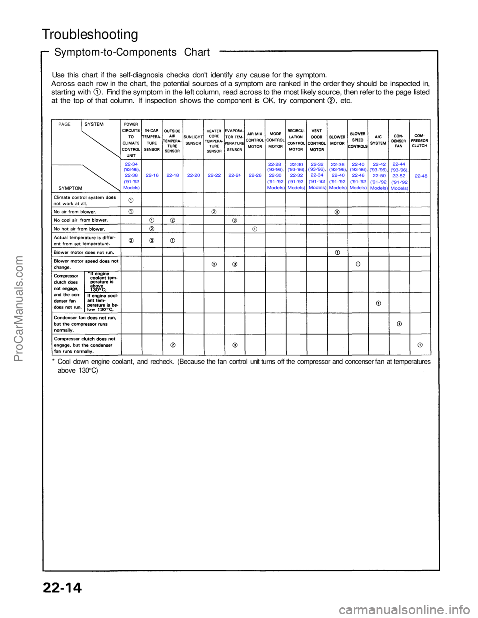
Troubleshooting
Symptom-to-Components Chart
Use this chart if the self-diagnosis checks don't identify any cause for the symptom.
Across each row in the chart, the potential sources of a symptom are ranked in the order they should be inspected in, starting with . Find the symptom in the left column, read across to the most likely source, then refer to the page listed
at the top of that column. If inspection shows the component is OK, try component , etc.
22-34
('93-'96),
22-38
('91-'92
Models)
22-16
22-18
22-20
22-22
22-24
22-26
22-30
('93-'96),22-28
('91-'92
Models)
22-30
('93-'96),
22-32
('91-'92
Models)
22-32
('93-'96),
22-34
('91-'92 Models)
22-36
('93-'96),
22-40
('91-'92 Models)
22-40
('93-'96),
22-46
('91-'92
Models)
22-42
('93-'96),
22-50
('91-'92 Models)
22-44
('93-'96),
22-52
('91-'92
Models)
22-48
PAGE
* Cool down engine coolant, and recheck. (Because the fan control unit turns off the compressor and condenser fan at temperatures above 130°C)ProCarManuals.com
Page 709 of 1640
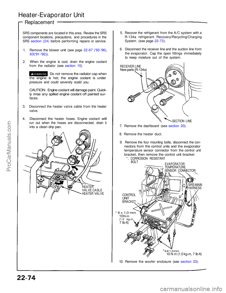
Heater-Evaporator Unit
Replacement
SRS components are located in this area. Review the SRS
component locations, precautions, and procedures in the
SRS section (24) before performing repairs or service.
1.
Remove
the
blower
unit
(see
page
22-67 ('93-'96),
63('91-'92)).
2. When the engine is cool, drain the engine coolant from the radiator (see section 10).
Do not remove the radiator cap when
the engine is hot; the engine coolant is under
pressure and could severely scald you.
CAUTION: Engine coolant will damage paint. Quick-
ly rinse any spilled engine coolant off painted sur-
faces.
3. Disconnect the heater valve cable from the heater valve.
4.
Disconnect
the
heater hoses. Engine cootant
will
run out when the hoses are disconnected, drain it
into a clean drip pan.
HEATER
VALVE CASLE
HEATER VALVE
5. Recover the refrigerant from the A/C system with a
R-134a refrigerant Recovery/Recycling/Charging
System. (see page 22-73).
6. Disconnect the receiver line and the suction line from the evaporator. Cap the open fittings immediately
to keep moisture out of the system.
RECEIVER LINE
New parts (R-134a)
SECTION LINE
7. Remove the dashboard (see section 20).
8. Remove the heater duct. 9. Remove the four mounting bolts, disconnect the con-
nectors from the control units and the evaporator
temperature sensor connector from the control unit
bracket, then remove the control unit bracket.
*: CORROSION RESISTANT BOLT
EVAPORATOR
TEMPERATURE
SENSOR CONNECTOR
CONTROL
UNIT
BRACKET
SRS MAIN
HARNESS
* 6 x 1,0 mm
10 N·m
(1.0 kg-m,
7 Ib-ft)
* 6 x 1.0 mm
10 N·m (1.0 kg-m, 7 Ib-ft)
10. Remove the woofer enclosure (see section 23).ProCarManuals.com