Page 779 of 1640
Radiator and Condenser Fan Controls
Description
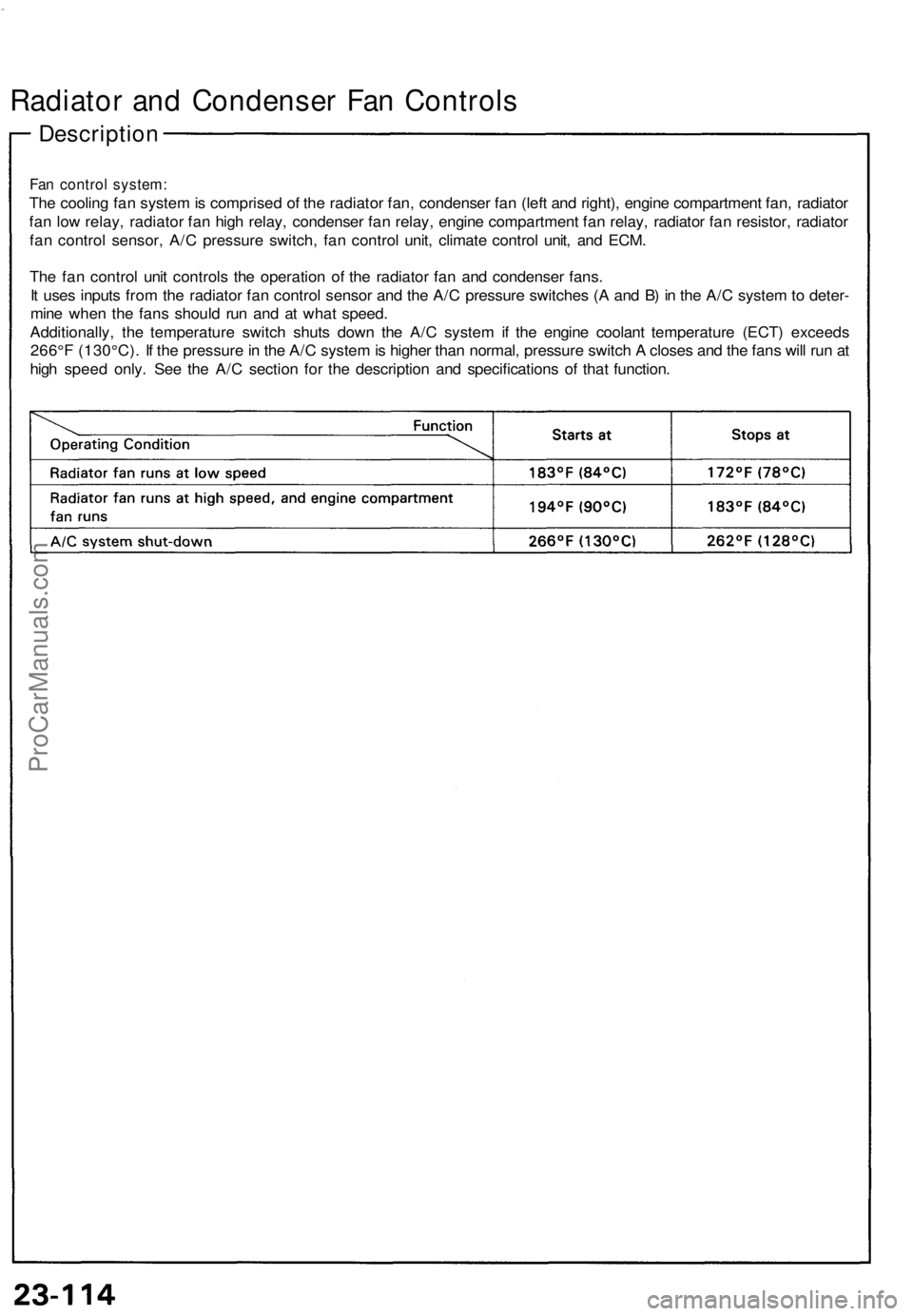
Fan control system:
The cooling fan system is comprised of the radiator fan, condenser fan (left and right), engine compartment fan, radiator
fan low relay, radiator fan high relay, condenser fan relay, engine compartment fan relay, radiator fan resistor, radiator
fan control sensor, A/C pressure switch, fan control unit, climate control unit, and ECM.
The fan control unit controls the operation of the radiator fan and condenser fans.
It uses inputs from the radiator fan control sensor and the A/C pressure switches (A and B) in the A/C system to deter-
mine when the fans should run and at what speed.
Additionally, the temperature switch shuts down the A/C system if the engine coolant temperature (ECT) exceeds
266°F (130°C). If the pressure in the A/C system is higher than normal, pressure switch A closes and the fans will run at
high speed only. See the A/C section for the description and specifications of that function.ProCarManuals.com
Page 786 of 1640
Gauge Assembly
Gauge/Terminal Location Index
SRS components are located in this area. Review the SRS component locations, precautions, and procedures in the SRS
section (24) before performing repairs or service.
SPEEDOMETER:
Indicates 60 mph [60km/h] at 1.026 [637]
rpm of the vehicle speed sensor (VSS).
FUEL GAUGE: Gauge test, page 23-134 Sending Unit Test, page 23-135
VOLTAGE METER:
If, with the No. 5 (15 A) fuse
and other gauges
OK, the pointer of the
voltage meter does not move at all,
replace the voltage
meter.
SAFETY INDICATOR SYSTEM:
See page 23-145 ('93-'96) ('91-'92)A/T GEAR POSITION
INDICATOR SYSTEM:
See page 23-156 ENGINE OIL PRESSURE
GAUGE:
Test page 23-137
ENGINE COOLANT TEMPERATURE (ECT) GAUGE:
Gauge Test, page 23-136 Sender Test, page 23-136
TACHOMETER:
Indicates 100 rpm at 300 pulses per minute
of the igniter unit.ProCarManuals.com
Page 790 of 1640
Disassembly
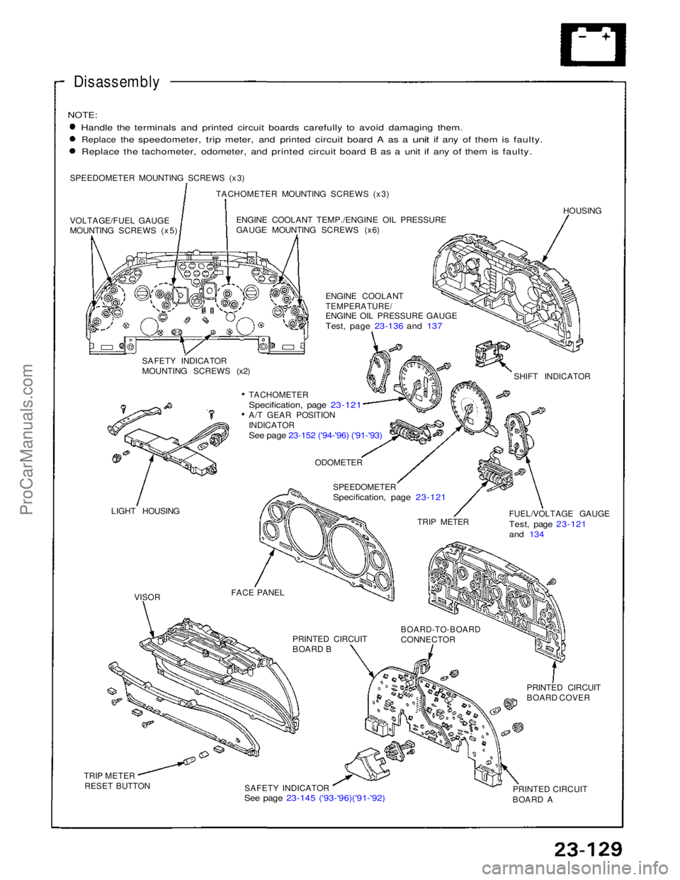
NOTE:
Handle the terminals and printed circuit boards carefully to avoid damaging them.
Replace
the
speedometer,
trip
meter,
and
printed
circuit
board
A as a
unit
if any of
them
is
faulty. Replace the tachometer, odometer, and printed circuit board B as a unit if any of them is faulty.
SPEEDOMETER MOUNTING SCREWS (x3) TACHOMETER MOUNTING SCREWS (x3)
VOLTAGE/FUEL GAUGE
MOUNTING SCREWS (x5) ENGINE COOLANT TEMP./ENGINE OIL PRESSURE
GAUGE MOUNTING SCREWS (x6)
HOUSING
ENGINE COOLANT
TEMPERATURE/
ENGINE OIL PRESSURE GAUGE
Test, page 23-136 and 137
SAFETY INDICATOR
MOUNTING SCREWS (x2) SHIFT INDICATOR
TACHOMETER
Specification, page 23-121
A/T GEAR POSITION
INDICATOR
See page 23-152 ('94-'96) ('91-'93)
LIGHT HOUSING
ODOMETER
SPEEDOMETER
Specification, page 23-121
TRIP METER FUEL/VOLTAGE GAUGE
Test, page 23-121
and 134
FACE PANEL PRINTED CIRCUIT
BOARD B
BOARD-TO-BOARD
CONNECTOR
PRINTED CIRCUIT
BOARD COVER
PRINTED CIRCUIT
BOARD A
SAFETY INDICATOR
See page 23-145 ('93-'96)('91-'92)
TRIP METER
RESET BUTTON
VISORProCarManuals.com
Page 984 of 1640
Cooling
Cooling System
Two cooling systems are employed:
An antifreeze/water system with the radiator mounted in the front of the vehicle.
An air-cooling system driven by a fan mounted in the engine compartment.
BLEEDER
RADIATOR
BLEEDER
WATER VALVE
HEATER CORE
DRAIN
DRAINS
BLEEDER
ENGINE DRAIN
WATER PUMP
ENGINE OIL
COOLER
ENGINE DRAIN
FAST IDLE THERMO VALVE
IDLE AIR CONTROL (IAC) VALVE
BREATHER PIPE
THROTTLE
BODY
THERMOSTAT
TEMPERATURE SWITCH
ENGINE COOLANT
BLEEDER
EXPANSION
TANKProCarManuals.com
Page 1002 of 1640
Cylinder Head/Valve Train
Illustrated Index
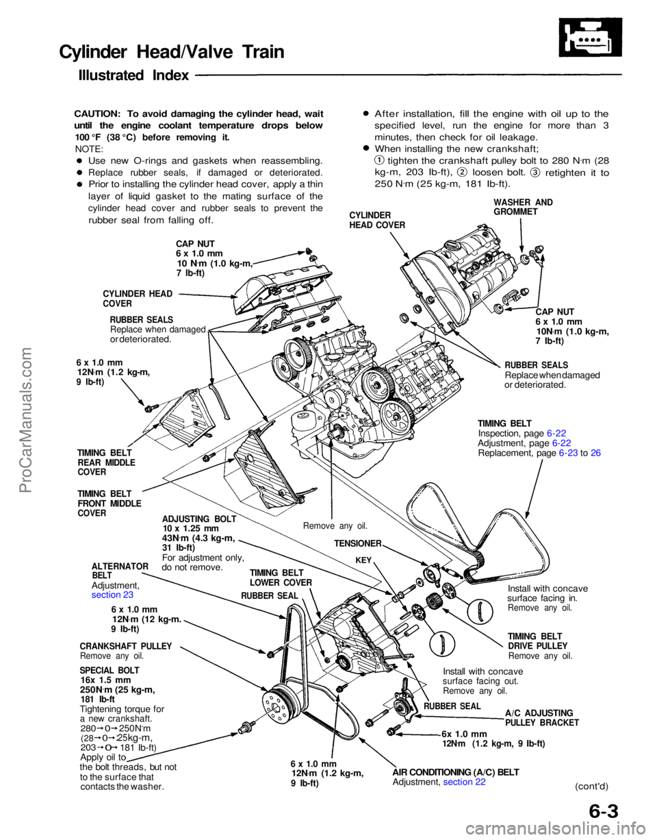
CAUTION: To avoid damaging the cylinder head, wait
until the engine coolant temperature drops below
100 °F (38 °C) before removing it.NOTE:
CAP NUT
6 x 1.0 mm
10 N .
m
(1.0 kg-m,
7 Ib-ft)
CYLINDER
HEAD COVER
WASHER AND
GROMMET
After installation, fill the engine with oil up to the
specified level, run the engine for more than 3
minutes, then check for oil leakage.
When installing the new crankshaft;
tighten the crankshaft pulley bolt to 280 N .
m (28
kg-m, 203 Ib-ft),
loosen bolt.
retighten it to
250 N .
m (25 kg-m, 181 Ib-ft).
CYLINDER HEAD
COVER
RUBBER SEALS
Replace when damaged
or deteriorated.
6 x 1.0 mm
12N .
m (1.2 kg-m,
9 Ib-ft)
TIMING BELT
REAR MIDDLE
COVER
TIMING BELT
FRONT MIDDLE
COVER
ADJUSTING BOLT
10 x
1.25
mm
43N .
m (4.3 kg-m,
31 Ib-ft)
For adjustment only,
do not remove.
ALTERNATOR
BELT
Adjustment,
section 23
6 x 1.0 mm
12N .
m
(12
kg-m.
9 Ib-ft)
CRANKSHAFT PULLEY
Remove any oil.
SPECIAL BOLT
16x 1.5 mm
250N .
m (25 kg-m,
181 Ib-ft
Tightening torque for
a new crankshaft.
203
Apply oil to
the bolt threads, but not
to the surface that contacts the washer.
6 x 1.0 mm
12N .
m (1.2 kg-m,
9 Ib-ft)
AIR CONDITIONING (A/C) BELT
Adjustment, section 22
6x 1.0 mm
12N .
m (1.2 kg-m, 9 Ib-ft)
(cont'd)
A/C ADJUSTING
PULLEY BRACKET
RUBBER SEAL
Install with concave
surface facing out.
Remove any oil.
TIMING BELT
DRIVE PULLEY
Remove any oil.
Install with concave
surface facing in.
Remove any oil.
TIMING BELT
Inspection, page 6-22
Adjustment, page 6-22 Replacement, page 6-23 to 26
RUBBER SEALS
Replace when damaged
or deteriorated.
CAP NUT
6 x 1.0 mm
10N .
m (1.0 kg-m,
7 Ib-ft)
TIMING BELT
LOWER COVER
RUBBER SEAL
KEY
Remove any oil.
TENSIONER
280
250N.m
25
kg-m,
181 Ib-ft)
(28
0
0
0
Use new O-rings and gaskets when reassembling.
Replace rubber seals, if damaged or deteriorated.
Prior to installing the cylinder head cover, apply a thin
layer of liquid gasket to the mating surface of the
cylinder head cover and rubber seals to prevent the
rubber seal from falling off.ProCarManuals.com
Page 1004 of 1640
REAR VARIABLE VALVE TIMING
AND VALVE LIFT ELECTRONIC CONTROL
SYSTEM (VTEC) SOLENOID VALVE
Troubleshooting, page 6-15, 16
EXHAUST GAS
RECIRCULATION (EGR) VALVE
6x1
.0mm 12N .
m (1.2kg-m,
9 Ib-ft)
FILTER Replace.
8x 1.25mm
22N .
m (2.2 kg-m,
16 Ib-ft)
ENGINE COOLANT
TEMPERATURE (ECT) SENSOR 180 N .
m (1.8 kg-m. 13 Ib-ft)
8x 1.25mm
22N .
m (2.2 kg-m, 16 Ib-ft)
FRONT VTEC SOLENOID VALVE
'Troubleshooting, page 6-15, 16
O-RING
Replace.
GASKET
Replace.
ROCKER
SHAFTS WASHERS
Replace.
SEALING BOLTS
60N.m (6.0 kg-m,
43 Ib-ft)
OIL PRESSURE GAUGE SENDING
UNIT (section 23)
8x 1.25mm
22N .
m (2.2 kg-m,
16 Ib-ft)
DOWEL PIN
O-RING
Replace.
ECT SWITCH
28 N ·
m
(2.8 kg-m.
20 Ib-ft)
O-RING
Replace.
ROCKER ARM ASSEMBLY
(PRIMARY, MID, SECONDARY)
Inspection, page 6-36
ROCKER SHAFT
ORIFICE
Remove with 5 mm
bolt and clean.
O-RING
Replace.
(cont'd)ProCarManuals.com
Page 1005 of 1640
Cylinder Head/Valve Train
Illustrated Index (cont'd)
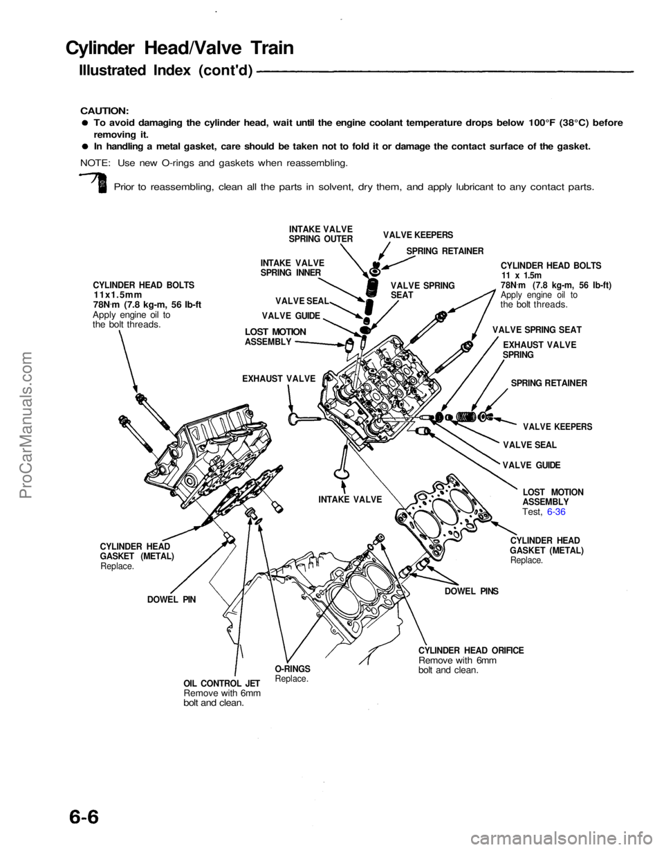
To avoid damaging the cylinder head, wait until the engine coolant temperature drops below 100°F (38°C) before
removing it.
In handling a metal gasket, care should be taken not to fold it or damage the contact surface of the gasket.
Prior to reassembling, clean all the parts in solvent, dry them, and apply lubricant to any contact parts.
INTAKE VALVE
SPRING OUTER
CYLINDER HEAD BOLTS
11x1.5mm
78N .
m (7.8 kg-m, 56 Ib-ft
Apply engine oil to
the bolt threads.
INTAKE VALVE
SPRING INNER
VALVE SEAL
VALVE GUIDE
LOST MOTION
ASSEMBLY
VALVE KEEPERS
SPRING RETAINER
VALVE SPRING SEAT CYLINDER HEAD BOLTS
11 x
1.5m
78N .
m (7.8 kg-m, 56 Ib-ft)
Apply engine oil to
the bolt threads.
VALVE SPRING SEAT EXHAUST VALVE
SPRING
SPRING RETAINER
VALVE KEEPERS
VALVE SEAL
VALVE GUIDE
LOST MOTION
ASSEMBLY
Test, 6-36
CYLINDER HEAD
GASKET (METAL) Replace.
DOWEL PINS
CYLINDER HEAD ORIFICE
Remove with 6mm
bolt and clean.
O-RINGS
Replace.
OIL CONTROL JET
Remove with 6mm
bolt and clean.
DOWEL PIN
CYLINDER HEAD
GASKET (METAL)
Replace. EXHAUST VALVE
INTAKE VALVE
CAUTION:
NOTE: Use new O-rings and gaskets when reassembling.ProCarManuals.com
Page 1014 of 1640
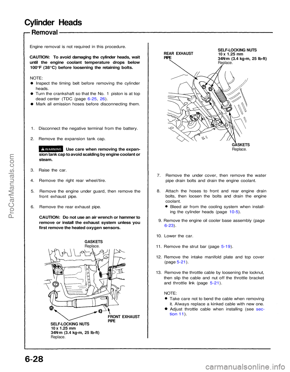
Cylinder Heads
Removal
Engine removal is not required in this procedure.
CAUTION: To avoid damaging the cylinder heads, wait until the engine coolant temperature drops below 100°F (38°C) before loosening the retaining bolts.
NOTE:
Inspect the timing belt before removing the cylinder
heads.
Turn the crankshaft so that the No. 1 piston is at top
dead center (TDC (page 6-25, 26). Mark all emission hoses before disconnecting them.
1. Disconnect the negative terminal from the battery.
2. Remove the expansion tank cap.
Use care when removing the expan-
sion tank cap to avoid scalding by engine coolant or
steam.
3. Raise the car.
4. Remove the right rear wheel/tire.
5. Remove the engine under guard, then remove the front exhaust pipe.
6. Remove the rear exhaust pipe.
CAUTION: Do not use an air wrench or hammer to
remove or install the exhaust system unless you
first remove the heated oxygen sensors.
GASKETS
Replace.
FRONT EXHAUST
PIPE
SELF-LOCKING NUTS
10 x
1.25
mm
34N .
m (3.4 kg-m, 25 Ib-ft)
Replace.
REAR EXHAUST
PIPE
SELF-LOCKING NUTS
10 x
1.25
mm
34N .
m (3.4 kg-m, 25 Ib-ft)
Replace.
GASKETS
Replace.
7. Remove the under cover, then remove the water pipe drain bolts and drain the engine coolant.
8. Attach the hoses to front and rear engine drain bolts, then loosen the bolts and drain the engine
coolant.
Bleed air from the cooling system when install-
ing the cylinder heads (page 10-5).
9. Remove the engine oil cooler base assembly (page
6-23).
10. Lower the car.
11. Remove the strut bar (page 5-19).
12. Remove the intake manifold plate and top cover (page 5-21).
13. Remove the throttle cable by loosening the locknut, then slip the cable and nut off the throttle bracketand throttle link (page 5-21).
NOTE:
Take care not to bend the cable when removingit. Always replace a kinked cable with new one.Adjust throttle cable when installing (see sec-
tion 11).ProCarManuals.com