1991 ACURA NSX cruise control
[x] Cancel search: cruise controlPage 228 of 1640

PGM-FI System
System Description
PGM-FI System
The PGM-FI system on this model is a sequential multiport fuel injection system.
Fuel Injector Timing and Duration
The ECM contains memories for the basic discharge durations at various engine speeds and manifold pressures. The
basic discharge duration, after being read out from the memory, is further modified by signals sent from various sensors
to obtain the final discharge duration.
Throttle Valve Control
The ECM controls the throttle valve control motor based on accelerator pedal position, TCS control unit and various sig-
nals. The ECM also controls the idle control function, cruise control function, and other functions with the throttle valve
control.
Ignition Timing Control
• The ECM contains memories for basic ignition timing at various engine speeds and manifold pressures. Ignition timing
is also adjusted for engine coolant temperature.
• A knock control system is also used. When detonation is detected by the knock sensor (KS), the ignition timing is
retarded.
Other Control Functions
1. Starting Control
When the engine is started, the ECM provides a rich mixture by increasing fuel injector duration.
2. Fuel Pump Control
• When the ignition switch is initially turned on, the ECM supplies ground to the PGM-FI main relay that supplies
current to the fuel pump for two seconds to pressurize the fuel system.
• When the engine is running, the ECM supplies ground to the PGM-FI main relay that supplies current to the fuel pump.
• When the engine is not running and the ignition is on, the ECM cuts ground to the PGM-FI main relay which cuts
current to the fuel pump.
• Excellent engine performance is achieved through the use of VTEC (Variable Valve Timing and Valve Lift Electronic
Control System), intake air bypass control and discharge volume control of the fuel pump.ProCarManuals.com
Page 235 of 1640
Drive B y Wir e Syste m
System Descriptio n
Cruise Contro l Functio n
Th e EC M control s th e throttl e valv e contro l moto r t o maintai n th e se t spee d whe n th e cruis e contro l syste m is operating .
Th e throttl e valv e contro l moto r take s th e plac e o f th e cruis e contro l actuator .
Tractio n Contro l Syste m (TCS ) Functio n
I f whee l spi n occur s durin g acceleratio n o r cornering , th e TC S contro l uni t request s th e EC M to reduc e th e engin e powe r
b y retardin g th e ignitio n timin g an d closin g th e throttl e valve . I f th e wheel s loc k during deceleration , th e TC S contro l uni t
signal s th e EC M to ope n th e throttl e valve .
Engin e Protectio n Functio n
Whe n th e engin e spee d exceed s 8,00 0 rp m (M/T ) o r 7,50 0 rp m (A/T) , th e EC M control s th e throttl e valve , regardles s o f th e
accelerato r position , t o protec t th e engin e fro m over-revving .
Fail-saf e Functio n
O n thi s system , th e EC M monitor s th e positio n o f th e accelerato r peda l wit h a dua l circui t typ e accelerato r positio n sensor ,
an d monitor s th e operatio n o f th e throttl e valv e contro l moto r wit h a Throttl e Positio n (TP ) sensor .
Whe n a n abnormalit y occur s i n th e system , th e EC M restrict s th e operatio n o f th e throttl e valv e contro l moto r t o allo w th e
engin e t o continu e t o run .
ProCarManuals.com
Page 427 of 1640
Steering Wheel
Removal
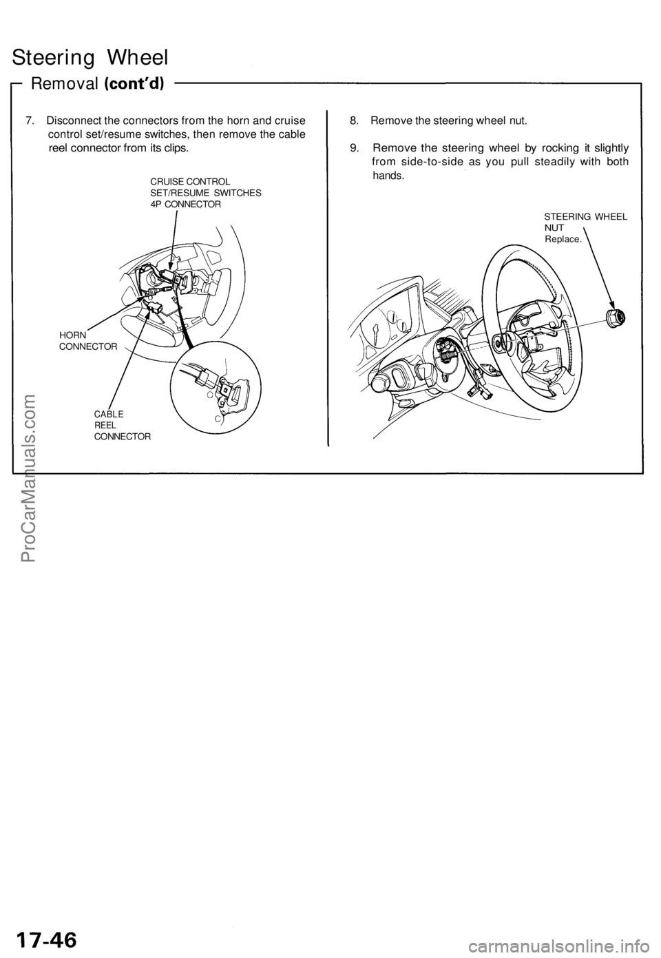
7. Disconnect the connectors from the horn and cruise
control set/resume switches, then remove the cable
reel connector from its clips.
CRUISE CONTROL
SET/RESUME SWITCHES
4P CONNECTOR
HORN
CONNECTOR
CABLE
REEL
CONNECTOR
8. Remove the steering wheel nut.
9. Remove the steering wheel by rocking it slightly
from side-to-side as you pull steadily with both
hands.
STEERING WHEEL
NUT
Replace.ProCarManuals.com
Page 429 of 1640
Installation
NOTE: Before installing the steering wheel, make sure
the front wheels are straight ahead.
CAUTION:
• Be sure to install the harness wires so that they are
not pinched or interfering with other car parts.
• Do not replace the original steering wheel with any
other design, since it will make it impossible to prop-
erly install the airbag. (Use only genuine Honda
replacement parts.)
• After reassembly, confirm that the wheels are still
straight ahead and that steering wheel spoke angle
is correct. If minor spoke angle adjustment is neces-
sary, adjust the tie-rods only. Do not remove and
reposition the steering wheel.
Confirm that the airbag assembly is securely
attached to the steering wheel; otherwise, severe per-
sonal injury could result during later airbag deploy-
ment.
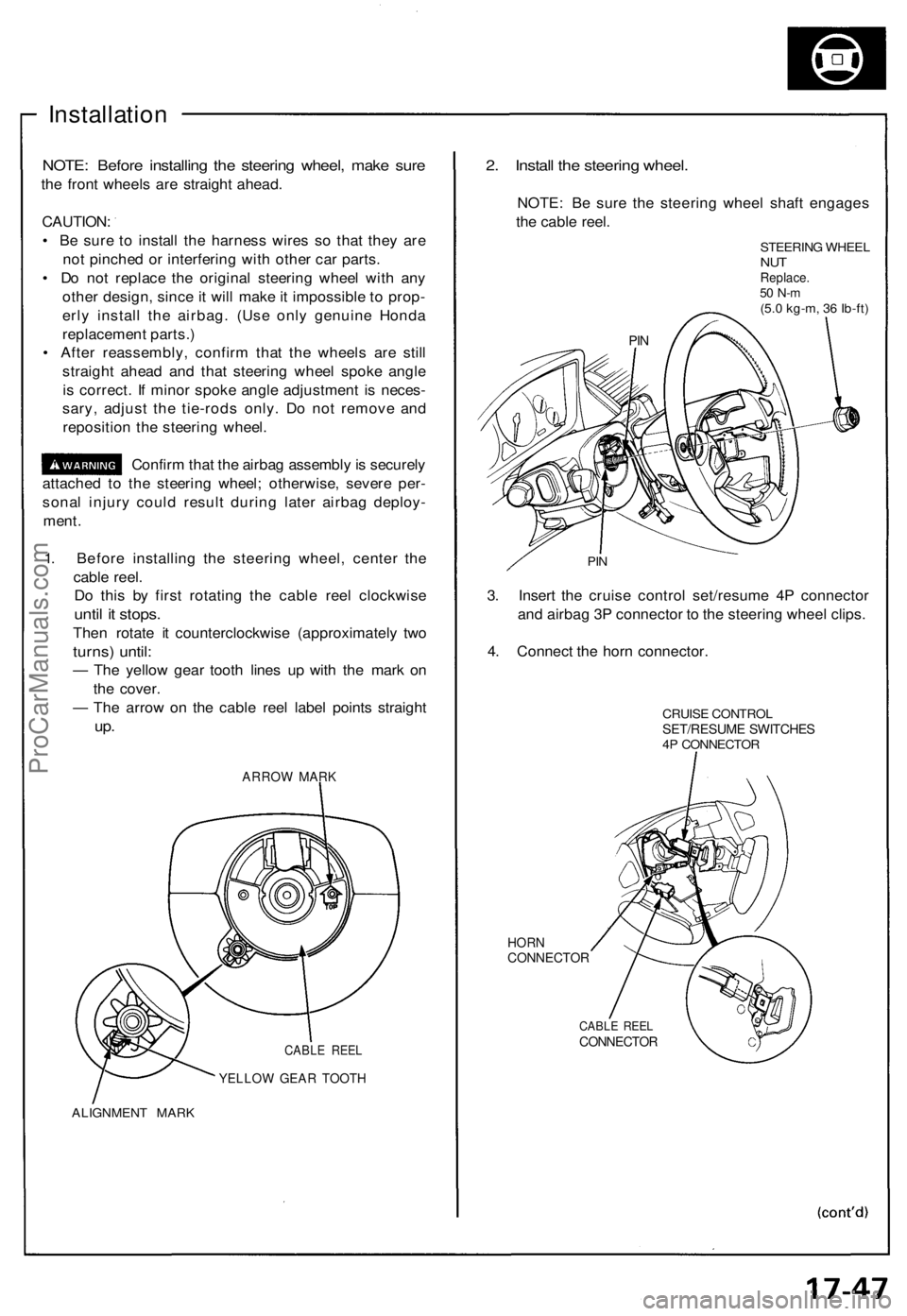
1. Before installing the steering wheel, center the
cable reel.
Do this by first rotating the cable reel clockwise
until it stops.
Then rotate it counterclockwise (approximately two
turns) until:
— The yellow gear tooth lines up with the mark on
the cover.
— The arrow on the cable reel label points straight
up.
ARROW MARK
CABLE REEL
YELLOW GEAR TOOTH
ALIGNMENT MARK
2. Install the steering wheel.
NOTE: Be sure the steering wheel shaft engages
the cable reel.
STEERING WHEEL
NUT
Replace.
50 N-m
(5.0 kg-m, 36 Ib-ft)
PIN
3. Insert the cruise control set/resume 4P connector
and airbag 3P connector to the steering wheel clips.
4. Connect the horn connector.
CRUISE CONTROL
SET/RESUME SWITCHES
4P CONNECTOR
HORN
CONNECTOR
CABLE REEL
CONNECTOR
PINProCarManuals.com
Page 430 of 1640
Steering Wheel
Installation
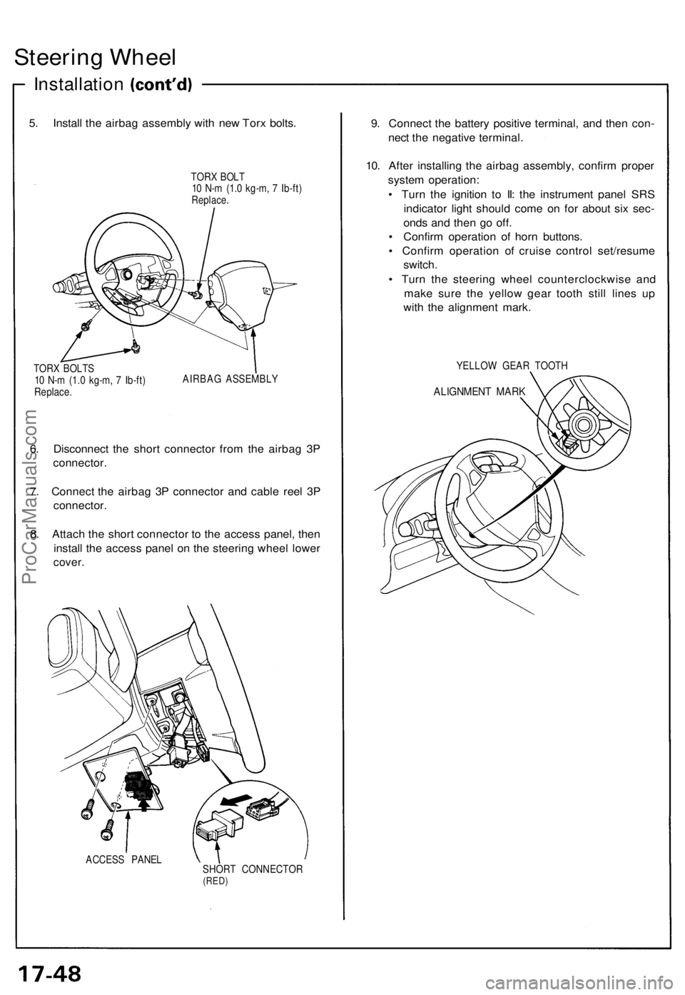
5. Install the airbag assembly with new Torx bolts.
TORX BOLT
10 N-m (1.0 kg-m, 7 Ib-ft)
Replace.
TORX BOLTS
10 N-m (1.0 kg-m, 7 Ib-ft)
Replace.
AIRBAG ASSEMBLY
6. Disconnect the short connector from the airbag 3P
connector.
7. Connect the airbag 3P connector and cable reel 3P
connector.
8. Attach the short connector to the access panel, then
install the access panel on the steering wheel lower
cover.
ACCESS PANEL
SHORT CONNECTOR
(RED)
9. Connect the battery positive terminal, and then con-
nect the negative terminal.
10. After installing the airbag assembly, confirm proper
system operation:
• Turn the ignition to II: the instrument panel SRS
indicator light should come on for about six sec-
onds and then go off.
• Confirm operation of horn buttons.
• Confirm operation of cruise control set/resume
switch.
• Turn the steering wheel counterclockwise and
make sure the yellow gear tooth still lines up
with the alignment mark.
YELLOW GEAR TOOTH
ALIGNMENT MARKProCarManuals.com
Page 933 of 1640
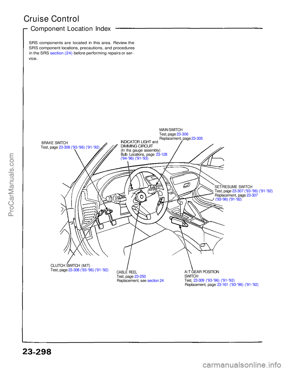
Cruise Control
Component Location Index
SRS components are located in this area. Review the
SRS component locations, precautions, and procedures
in the SRS section (24) before performing repairs or ser-
vice.
BRAKE SWITCH
Test, page 23-308 ('93-'96) ('91-'92) INDICATOR LIGHT and
DIMMIN
G
CIRCUIT
(In tha gauge assembly)
Bulb Locations, page 23-128
('94-'96) ('91-'93)
MAIN SWITCH
Test, page 23-306 Replacement, page 23-305
SET/RESUME SWITCH
Test, page 23-307 ('93-'96) ('91-'92)
Replacement, page 23-307('93-'96) ('91-'92)
A/T GEAR POSITION
SWITCH
Test, 23-309 ('93-'96) ('91-'92) Replacement, page 23-161 ('93-'96) ('91-'92)
CABLE REEL
Test, page 23-250
Replacement, see section 24
CLUTCH SWITCH (M/T)
Test, page 23-308 ('93-'96) ('91-'92)ProCarManuals.com
Page 935 of 1640
Cruise Control
Description
The cruise control system uses mechanically and electri-
cally operated devices to maintain vehicle speed at a
setting selected by the driver.
The ECM receives command signals from the cruise con-
trol main switch and the cruise control set/resume switch.
It receives information about operating conditions from
the brake switch, vehicle speed sensor (VSS), the clutch
switch (with manual transmission), or the A/T gear posi-
tion switch (with automatic transmission). The ECM
sends operational signals to the devices that regulate the
throttle position. The throttle position maintains the
selected vehicle speed. Essentially, the ECM compares
the actual speed of the vehicle to the selected speed.
Then, it uses the result of that comparison to open or
close the throttle.
The brake switch releases the system's control of the
throttle at the instant the driver depresses the brake
pedal. The switch sends an electronic signal to the ECM
when the brake pedal is depressed; the ECM responds
by allowing the throttle to close. The clutch switch (man-
ual transmission) or the A/T gear position switch (auto-
matic transmission) sends a disengage signal to the
ECM that also allows the throttle to close.
Operation:
The cruise control system will set and automatically
maintain any speed above 25 mph (45 km/h). To set,
make sure that the main switch is in the "ON" position.
After reaching the desired speed, press the set switch.
The ECM will receive a set signal and, in turn, will actu-
ate the throttle valve control motor. When the set switch
is depressed and the cruise control system is on, the
"cruise control" ON indicator in the gauge assembly will
light up. You can cancel the cruise control system by
pushing the main switch to "OFF". This erases the set
speed from memory. If the system is disengaged tem-
porarily by the brake switch, clutch switch, or A/T gear
position switch and vehicle speed is still above 25 mph,
press the resume switch. With the resume switch
depressed and the set memory retained, the vehicle
automatically returns to the previous set speed.
For gradual acceleration without depressing the acceler-
ator pedal, push the resume switch down and hold it
there until the desired speed is reached. This will send
an acceleration signal to the ECM. When the switch is
released, the system will be reprogrammed for the new
speed. To slow down, depress the set switch. This will
send a deceleration signal to the ECM causing the car to
coast until the desired speed is reached. When the
desired speed is reached, release the set switch. This
will reprogram the system for the new speed.ProCarManuals.com
Page 936 of 1640
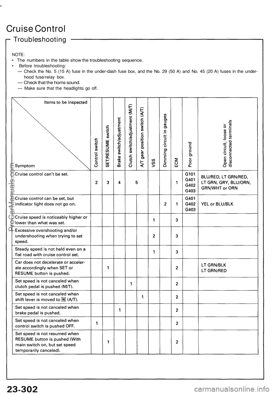
Troubleshooting
Cruise Control
NOTE:
• The numbers in the table show the troubleshooting sequence.
• Before troubleshooting:
— Check the No. 5 (15 A) fuse in the under-dash fuse box, and the No. 29 (50 A) and No. 45 (20 A) fuses in the under-
hood fuse/relay box.
— Check that the horns sound.
— Make sure that the headlights go off.ProCarManuals.com