1991 ACURA NSX spare tire
[x] Cancel search: spare tirePage 437 of 1640
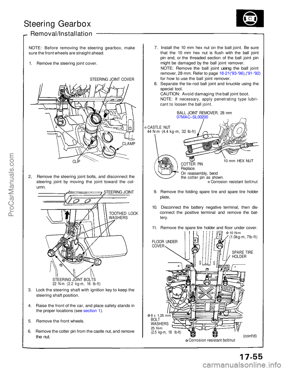
Steering Gearbox
Removal/Installation
NOTE: Before removing the steering gearbox, make
sure the front wheels are straight ahead. 1. Remove the steering joint cover.
STEERING JOINT COVER
7. Install the 10 mm hex nut on the balt joint. Be sure
that the 10 mm hex nut is flush with the ball joint
pin end, or the threaded section of the ball joint pin
might be damaged by the ball joint remover.
NOTE: Remove
the
ball
joint
using
the
ball
joint
remover, 28 mm. Refer to page 18-21('93-'96),('91-'92)
for how to use the ball joint remover.
8. Separate the tie-rod ball joint and knuckle using the
special tool.
CAUTION: Avoid damaging the ball joint boot.
NOTE: If necessary, apply penetrating type lubri-
cant to loosen the ball joint.
BALL JOINT REMOVER. 28 mm
07MAC–SL00200
CASTLE NUT
44 N·m (4.4 kg-m, 32 Ib-ft)
10 mm HEX NUT
CLAMP
CLIP
COTTER PIN
Replace.
On reassembly, bend
the cotter pin as shown.
Corrosion resistant bolt/nut
9. Remove the folding spare tire and spare tire holder plate,
10. Disconnect the battery negative terminal, then dis- connect the positive terminal and remove the bat-
tery.
11. Remove the spare tire holder and floor under cover.
FLOOR UNDER
COVER
10 N·m
(1.0kg-m, 7lb-ft)
SPARE TIRE
HOLDER
2, Remove the steering joint bolts, and disconnect the
steering joint by moving the joint toward the col-
umn.
STEERING JOINT
TOOTHED LOCK
WASHERS
STEERING JOINT BOLTS
22 N·m (2.2 kg-m, 16 Ib-ft)
3. Lock the steering shaft with ignition key to keep the steering shaft position.
4. Raise the front of the car, and place safety stands in the proper locations (see section 1).
5. Remove the front wheels.
6. Remove the cotter pin from the castle nut, and remove
the
nut.
8 x
1.25
mm
BOLT
WASHERS
25 N·m
(2.5 kg-m, 18 lb-ft)
Corrosion resistant bolt/nut
(cont'd)ProCarManuals.com
Page 703 of 1640
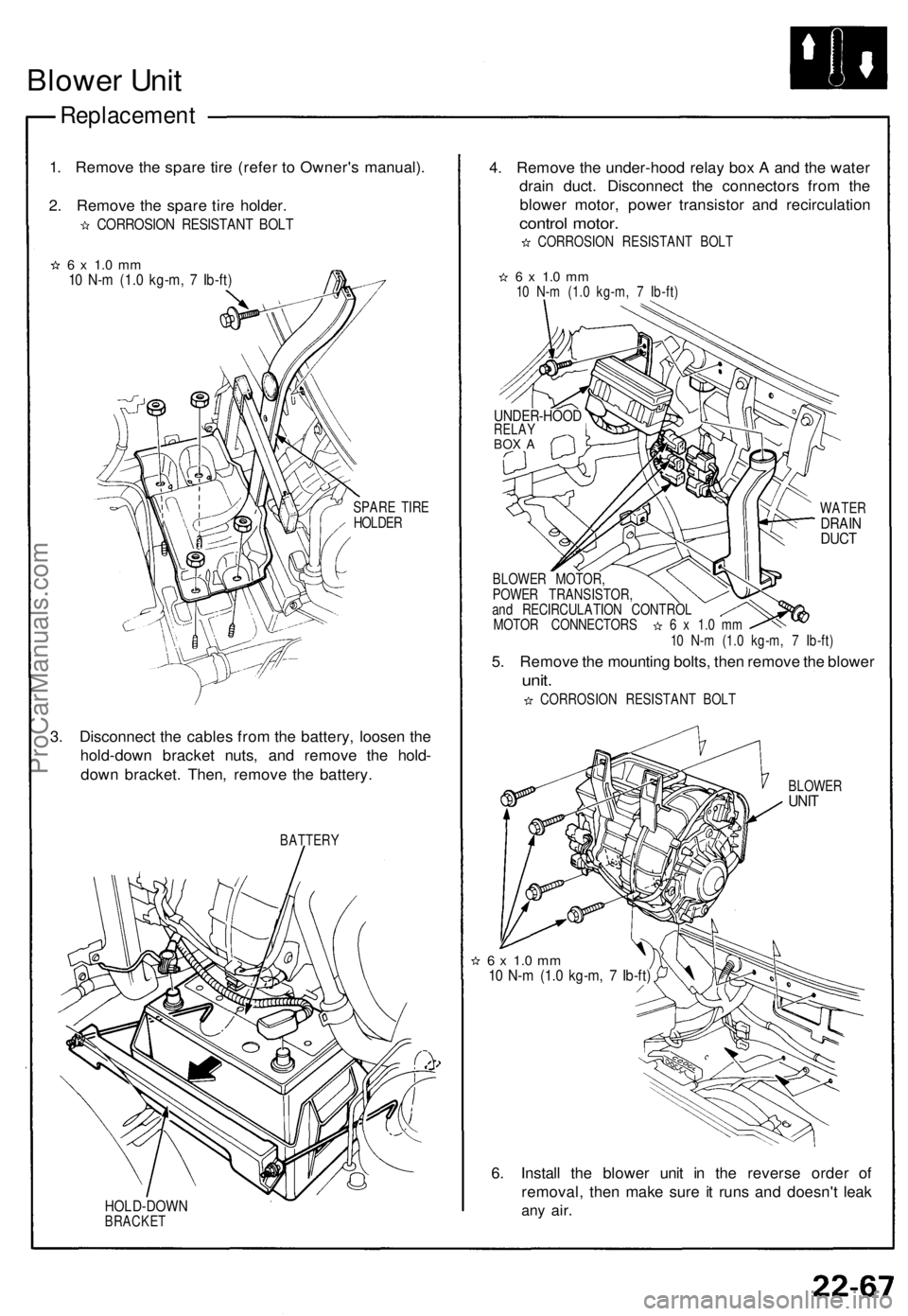
Blower Unit
Replacement
1. Remove the spare tire (refer to Owner's manual).
2. Remove the spare tire holder.
CORROSION RESISTANT BOLT
6 x 1.0 mm
10 N-m (1.0 kg-m, 7 Ib-ft)
SPARE TIRE
HOLDER
3. Disconnect the cables from the battery, loosen the
hold-down bracket nuts, and remove the hold-
down bracket. Then, remove the battery.
BATTERY
HOLD-DOWN
BRACKET
4. Remove the under-hood relay box A and the water
drain duct. Disconnect the connectors from the
blower motor, power transistor and recirculation
control motor.
CORROSION RESISTANT BOLT
6 x 1.0 mm
10 N-m (1.0 kg-m, 7 Ib-ft)
WATER
DRAIN
DUCT
BLOWER MOTOR,
POWER TRANSISTOR,
and RECIRCULATION CONTROL
MOTOR CONNECTORS 6 x 1.0 mm
10 N-m (1.0 kg-m, 7 Ib-ft)
5. Remove the mounting bolts, then remove the blower
unit.
CORROSION RESISTANT BOLT
BLOWER
UNIT
6 x 1.0 mm
10 N-m (1.0 kg-m, 7 Ib-ft)
6. Install the blower unit in the reverse order of
removal, then make sure it runs and doesn't leak
any
air.
UNDER-HOOD
RELAY
BOX AProCarManuals.com
Page 738 of 1640
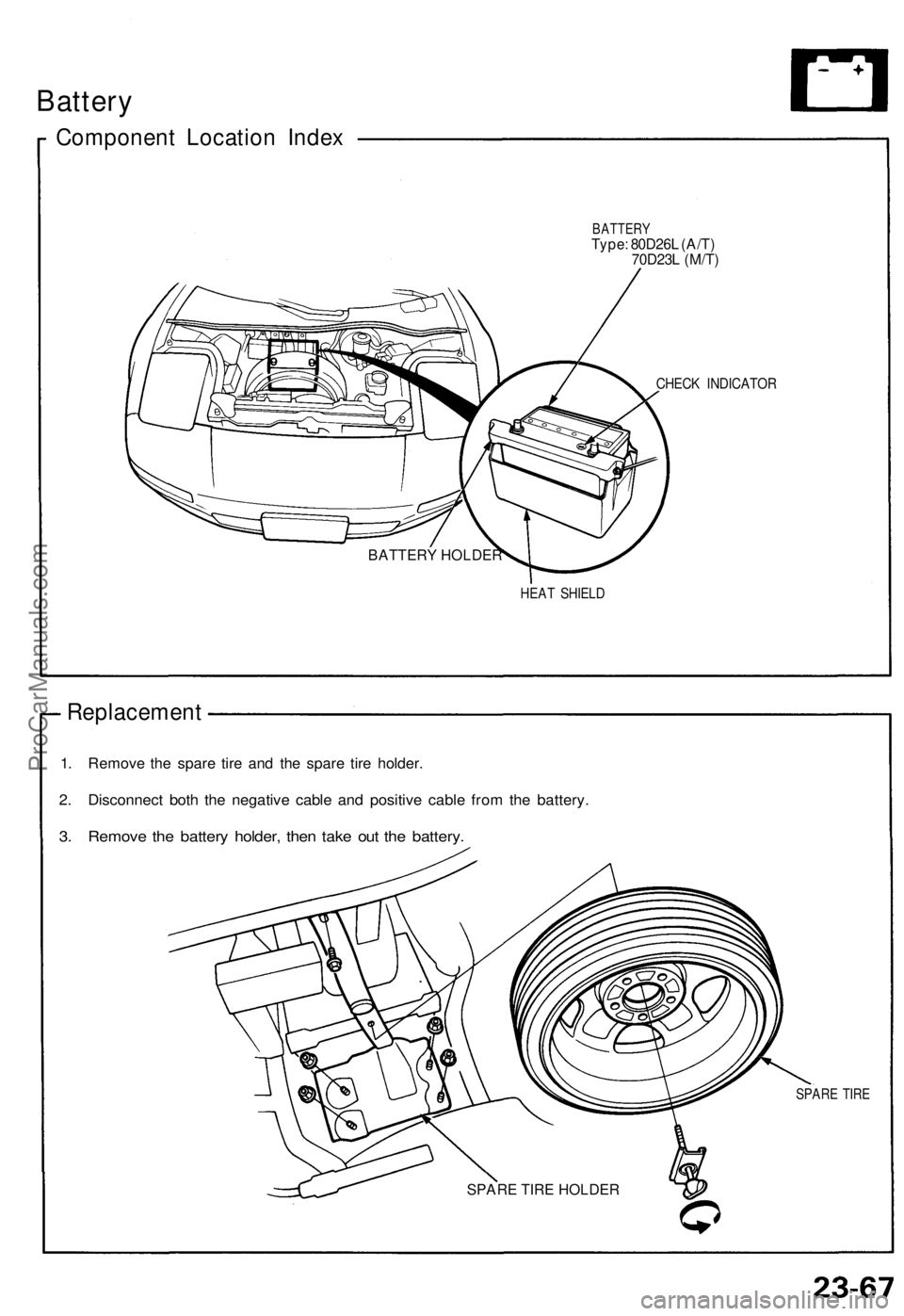
Battery
Componen t Locatio n Inde x
BATTER YType: 80D26 L (A/T )
70D23 L (M/T )
CHEC K INDICATO R
HEAT SHIEL D
Replacemen t
1. Remov e th e spar e tir e an d th e spar e tir e holder .
2. Disconnec t bot h th e negativ e cabl e an d positiv e cabl e fro m th e battery .
3. Remov e th e batter y holder , the n tak e ou t th e battery .
SPARE TIR E
SPARE TIRE HOLDER
BATTERY HOLDER
ProCarManuals.com
Page 1312 of 1640
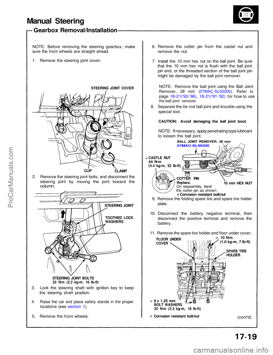
Manual Steering
Gearbox Removal/Installation
NOTE: Before removing the steering gearbox, make
sure the front wheels are straight ahead.
1. Remove the steering joint cover.
STEERING JOINT COVER
CLAMP
CLIP
2. Remove the steering joint bolts, and disconnect the steering joint by moving the joint toward the
column.
STEERING JOINT
STEERING JOINT BOLTS
22 N .
m (2.2 kg-m, 16 Ib-ft)
3. Lock the steering shaft with ignition key to keep the steering shaft position.
4. Raise the car and place safety stands in the proper
locations (see section 1).
5. Remove the front wheels.
8 x
1.25
mm
BOLT WASHERS
25 N .
m (2.5 kg-m, 18 Ib-ft)
Corrosion resistant bolt/nut
FLOOR UNDER
COVER
9. Remove the folding spare tire and spare tire holder
plate.
10. Disconnect the battery negative terminal, then disconnect the positive terminal and remove the
battery.
11. Remove the spare tire holder and floor under cover.
10 N·
m
(1.0 kg-m, 7 Ib-ft)
SPARE TIRE
HOLDER
(cont'd)
COTTER PIN
Replace.
On reassembly, bend
the cotter pin as shown.
Corrosion resistant bolt/nut
CASTLE NUT
44 N
·
m
(4.4 kg-m, 32 Ib-ft)
10 mm HEX NUT
NOTE: If necessary, apply penetrating type lubricant
to loosen the ball joint.
BALL JOINT REMOVER. 28 mm
07MAC-SL00200
6. Remove the cotter pin from the castel nut and
remove the nut.
7. Install the 10 mm hex nut on the ball joint. Be sure that the 10 mm hex nut is flush with the ball joint
pin end, or the threaded section of the ball joint pin
might be damaged by the ball joint remover.
NOTE: Remove the ball joint using the Ball Joint
Remover, 28 mm (07MAC-SL00200). Refer to
page 18-21('93-'96), 18-21('91-'92) for how to use
8. Separate the tie-rod ball joint and knuckle using the special tool.
CAUTION: Avoid damaging the ball joint boot.
TOOTHED LOCK
WASHERSProCarManuals.com
Page 1340 of 1640
Power Steering
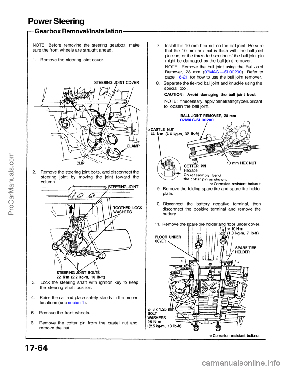
Gearbox Removal/Installation
NOTE: Before removing the steering gearbox, make
sure the front wheels are straight ahead.
1. Remove the steering joint cover.
STEERING JOINT COVER
CLAMP
CLIP
2. Remove the steering joint bolts, and disconnect the steering joint by moving the joint toward the
STEERING JOINT
column.
STEERING JOINT BOLTS
22 N.
m (2.2 kg-m, 16 Ib-ft)
3. Lock the steering shaft with ignition key to keep the steering shaft position.
4. Raise the car and place safety stands in the proper
locations (see secion 1).
5. Remove the front wheels.
6. Remove the cotter pin from the castel nut and remove the nut. 7. Install the 10 mm hex nut on the ball joint. Be sure
that the 10 mm hex nut is flush with the ball joint
pin end, or the threaded section of the ball joint pin
might be damaged by the ball joint remover.
NOTE: Remove the ball joint using the Ball Joint
Remover, 28 mm (07MAC —SL00200). Refer to
page 18-21 for how to use the ball joint remover.
8. Separate the tie-rod ball joint and knuckle using the special tool.
CAUTION: Avoid damaging the ball joint boot.
NOTE: If necessary, apply penetrating type lubricant
to loosen the ball joint.
BALL JOINT REMOVER, 28 mm
07MAC-SL00200
CASTLE NUT
44 N .
m (4.4 kg-m, 32 Ib-ft)
COTTER PIN
Replace.
10 mm HEX NUT
Corrosion resistant bolt/nut
9. Remove the folding spare tire and spare tire holder plate.
10. Disconnect the battery negative terminal, then disconnect the positive terminal and remove the
battery.
11. Remove the spare tire holder and floor under cover.
10 N·m
SPARE TIRE
HOLDER
FLOOR UNDER
COVER
8 x
1.25
mm
BOLT
WASHERS
25 N .
m
(2.5 kg-m, 18 Ib-ft)
Corrosion resistant bolt/nut
TOOTHED LOCK
WASHERS
(1.0 kg-m, 7 Ib-ft)ProCarManuals.com
Page 1365 of 1640
Troubleshooting
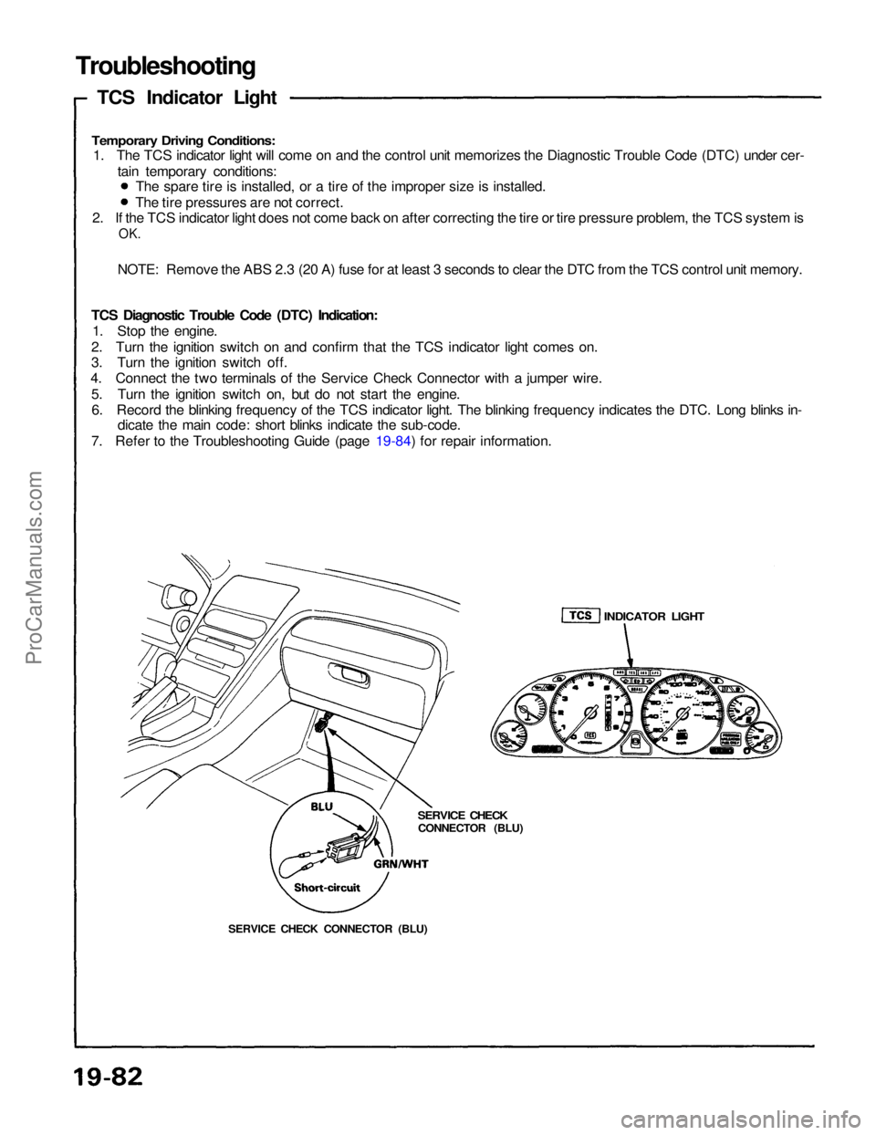
TCS Indicator Light
Temporary Driving Conditions:
1. The TCS indicator light will come on and the control unit memorizes the Diagnostic Trouble Code (DTC) under cer-
tain temporary conditions:
2. If the TCS indicator light does not come back on after correcting the tire or tire pressure problem, the TCS system is
OK.
NOTE: Remove the ABS 2.3 (20 A) fuse for at least 3 seconds to clear the DTC from the TCS control unit memory.
TCS Diagnostic Trouble Code (DTC) Indication: 1. Stop the engine.
2. Turn the ignition switch on and confirm that the TCS indicator light comes on.
3. Turn the ignition switch off.
4. Connect the two terminals of the Service Check Connector with a jumper wire.
5. Turn the ignition switch on, but do not start the engine.6. Record the blinking frequency of the TCS indicator light. The blinking frequency indicates the DTC. Long blinks in- dicate the main code: short blinks indicate the sub-code.
7. Refer to the Troubleshooting Guide (page 19-84) for repair information. The spare tire is installed, or a tire of the improper size is installed.
The tire pressures are not correct.
SERVICE CHECK CONNECTOR (BLU)
SERVICE CHECK
CONNECTOR (BLU)
INDICATOR LIGHTProCarManuals.com
Page 1573 of 1640
Modulator/Solenoid Unit
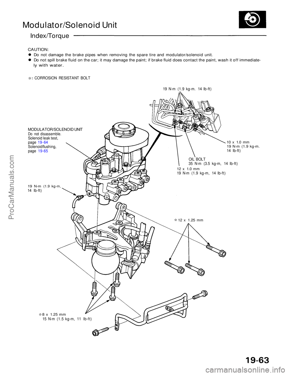
Index/Torque
CAUTION:
Do not damage the brake pipes when removing the spare tire and modulator/solenoid unit.
Do not spill brake fluid on the car; it may damage the paint; if brake fluid does contact the paint, wash it off immediate-
ly with water.
CORROSION RESISTANT BOLT 19 N·m (1.9 kg-m. 14 Ib-ft)
MODULATOR/SOLENOID UNIT
Do not disassemble.
Solenoid leak test,
page 19 - 64
Solenoid flushing,
page
19-65
19 N·m
(1.9 kg-m,
14 Ib-ft)
8 x
1.25
mm
15 N·m (1.5 kg-m, 11 Ib-ft)
12 x
1.25
mm
12 x 1.0 mm
19 N·m (1.9 kg-m, 14 Ib-ft)
OIL BOLT
35 N·m (3.5 kg-m, 14 Ib-ft)
10 x 1.0 mm
19 N·m
(1.9 kg-m.
14 Ib-ft)ProCarManuals.com