1991 ACURA NSX traction control
[x] Cancel search: traction controlPage 449 of 1640
System Description
Suspension Composition
Outline
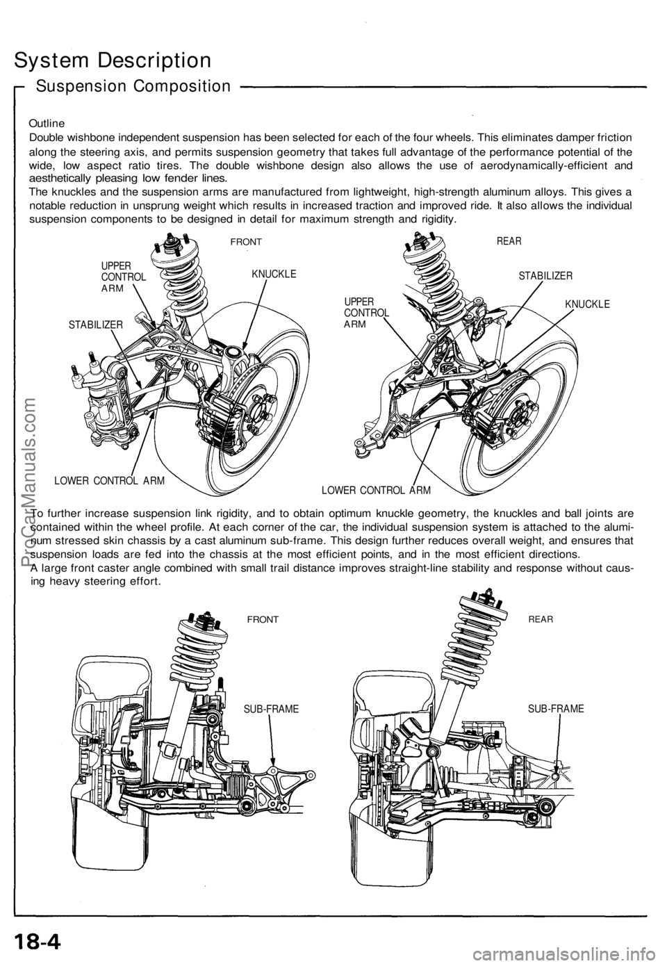
Double wishbone independent suspension has been selected for each of the four wheels. This eliminates damper friction
along the steering axis, and permits suspension geometry that takes full advantage of the performance potential of the
wide, low aspect ratio tires. The double wishbone design also allows the use of aerodynamically-efficient and
aesthetically pleasing low fender lines.
The knuckles and the suspension arms are manufactured from lightweight, high-strength aluminum alloys. This gives a
notable reduction in unsprung weight which results in increased traction and improved ride. It also allows the individual
suspension components to be designed in detail for maximum strength and rigidity.
FRONT
UPPER
CONTROL
ARM
KNUCKLE
STABILIZER
REAR
UPPER
CONTROL
ARM
STABILIZER
KNUCKLE
LOWER CONTROL ARM
LOWER CONTROL ARM
To further increase suspension link rigidity, and to obtain optimum knuckle geometry, the knuckles and ball joints are
contained within the wheel profile. At each corner of the car, the individual suspension system is attached to the alumi-
num stressed skin chassis by a cast aluminum sub-frame. This design further reduces overall weight, and ensures that
suspension loads are fed into the chassis at the most efficient points, and in the most efficient directions.
A large front caster angle combined with small trail distance improves straight-line stability and response without caus-
ing heavy steering effort.
FRONT
REAR
SUB-FRAME
SUB-FRAMEProCarManuals.com
Page 1362 of 1640
System Description
TCS Control unit
Acceleration Control:
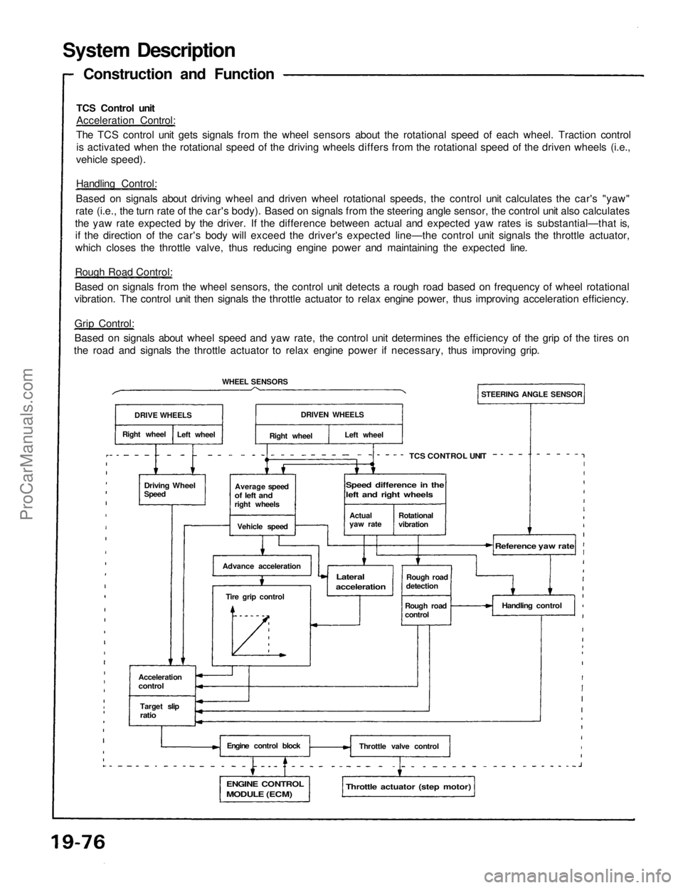
The TCS control unit gets signals from the wheel sensors about the rotational speed of each wheel. Traction control
is activated when the rotational speed of the driving wheels differs from the rotational speed of the driven wheels (i.e.,
vehicle speed).
Handling Control:
Based on signals about driving wheel and driven wheel rotational speeds, the control unit calculates the car's "yaw"
rate (i.e., the turn rate of the car's body). Based on signals from the steering angle sensor, the control unit also calculates
the yaw rate expected by the driver. If the difference between actual and expected yaw rates is substantial—that is,
if the direction of the car's body will exceed the driver's expected line—the control unit signals the throttle actuator,
which closes the throttle valve, thus reducing engine power and maintaining the expected line.
Rough Road Control:
Based on signals from the wheel sensors, the control unit detects a rough road based on frequency of wheel rotational
vibration. The control unit then signals the throttle actuator to relax engine power, thus improving acceleration efficiency.
Grip Control:
Based on signals about wheel speed and yaw rate, the control unit determines the efficiency of the grip of the tires on
the road and signals the throttle actuator to relax engine power if necessary, thus improving grip.
Construction and Function
DRIVE WHEELS
Right wheel
Left wheel
WHEEL SENSORS
Driving Wheel
Speed
Average speed
of left and
right wheels
Vehicle speed
Advance acceleration
Tire grip control
Acceleration
control
Target slip
ratio
Engine control block
ENGINE CONTROL
MODULE (ECM)
Throttle actuator (step motor)
Throttle valve control
Handling control
Rough road
detection
Rough road
control
Reference yaw rate
Lateral
acceleration
TCS CONTROL UNIT
STEERING ANGLE SENSOR
DRIVEN WHEELS
Right wheel
Left wheel
Actual
yaw rate
Rotational
vibration
Speed difference in the
left and right wheelsProCarManuals.com
Page 1363 of 1640
Fail-Safe Function:
If the control unit detects an abnormality, it shuts the
traction control system off and causes the TCS in-
dicator light to come on. However if the abnormality is
detected while the TCS is activated, the control unit
first establishes the appropriate wheel spin velocity,
then shuts the system down, thus preventing excessive
wheel spin.
Self-Diagnosis Function:
If the control unit detects an abnormality, it records a
Diagnostic Trouble Code (DTC) which can be used to
diagnose the problem. The DTC is shown at the TCS in-
dicator light when the Service Check connector ter-
minals are connected with a jumper wire.
Steering Angle Detection
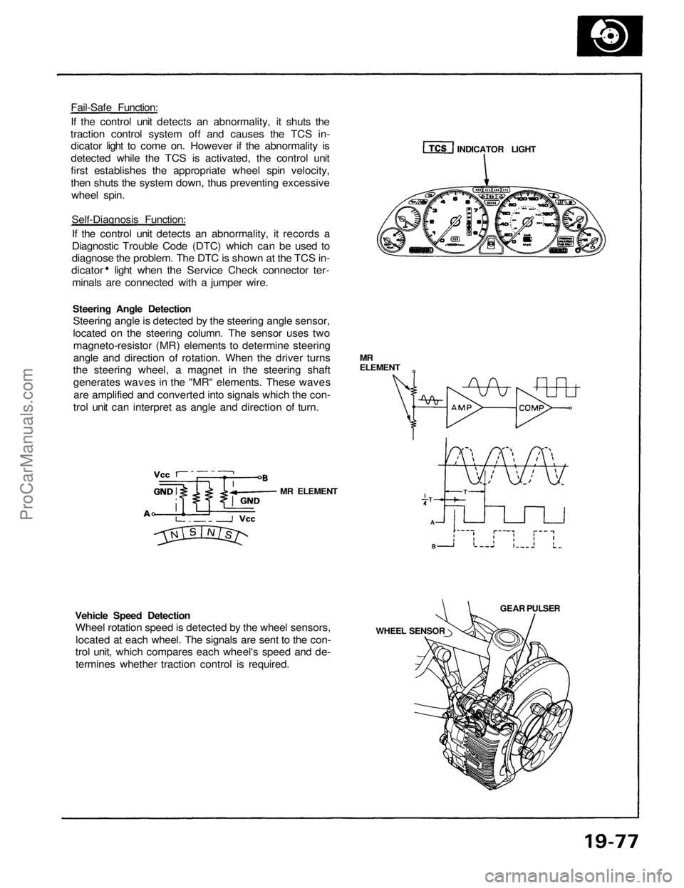
Steering angle is detected by the steering angle sensor,
located on the steering column. The sensor uses two
magneto-resistor (MR) elements to determine steering
angle and direction of rotation. When the driver turns
the steering wheel, a magnet in the steering shaft
generates waves in the "MR" elements. These waves
are amplified and converted into signals which the con-
trol unit can interpret as angle and direction of turn.
Vehicle Speed Detection
Wheel rotation speed is detected by the wheel sensors,
located at each wheel. The signals are sent to the con-
trol unit, which compares each wheel's speed and de-
termines whether traction control is required.
MR ELEMENT
WHEEL SENSOR
GEAR PULSER
MR
ELEMENT
INDICATOR LIGHTProCarManuals.com
Page 1364 of 1640
System Description
Engine Output Control
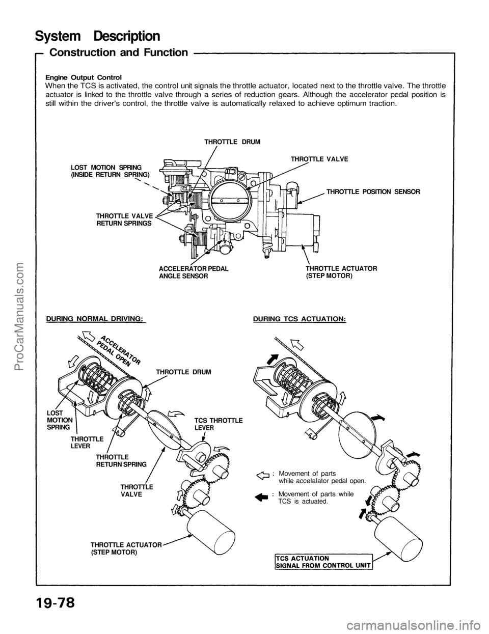
When the TCS is activated, the control unit signals the throttle actuator, located next to the throttle valve. The throttle
actuator is linked to the throttle valve through a series of reduction gears. Although the accelerator pedal position is
still within the driver's control, the throttle valve is automatically relaxed to achieve optimum traction.
Construction and Function
LOST MOTION SPRING
(INSIDE RETURN SPRING)
THROTTLE VALVE
RETURN SPRINGS
DURING NORMAL DRIVING:
LOST
MOTION
SPRING
THROTTLE
LEVER
THROTTLE
RETURN SPRING
THROTTLE DRUM
THROTTLE
VALVE
THROTTLE ACTUATOR
(STEP MOTOR)
Movement of parts
while accelalator pedal open.
Movement of parts while
TCS is actuated.
DURING TCS ACTUATION:
THROTTLE ACTUATOR
(STEP MOTOR)
THROTTLE POSITION SENSOR
THROTTLE VALVE
THROTTLE DRUM
ACCELERATOR PEDAL
ANGLE SENSOR
TCS THROTTLE
LEVERProCarManuals.com
Page 1569 of 1640
Troubleshooting
Anti-lock Brake System Indicator Light
Temporary Driving Conditions:
1. The anti-lock brake system indicator light will come
on and the control unit memorizes the problem
under certain conditions.
NOTE: Problem codes are explained on pages
19 - 46.
The tire(s) adhesion is lost due to excessive cor-
nering speed.
Problem codes: 5, 5-4, 5-8. The vehicle loses traction when starting from a
stuck condition on a muddy, snowy, or sandy
road.
Problem code: 4-1, 4-2, 4-4, 4-8. When the parking brake is applied for more than
30 seconds while the vehicle is being driven.
Problem code: 2. The vehicle is driven on extremely rough road.
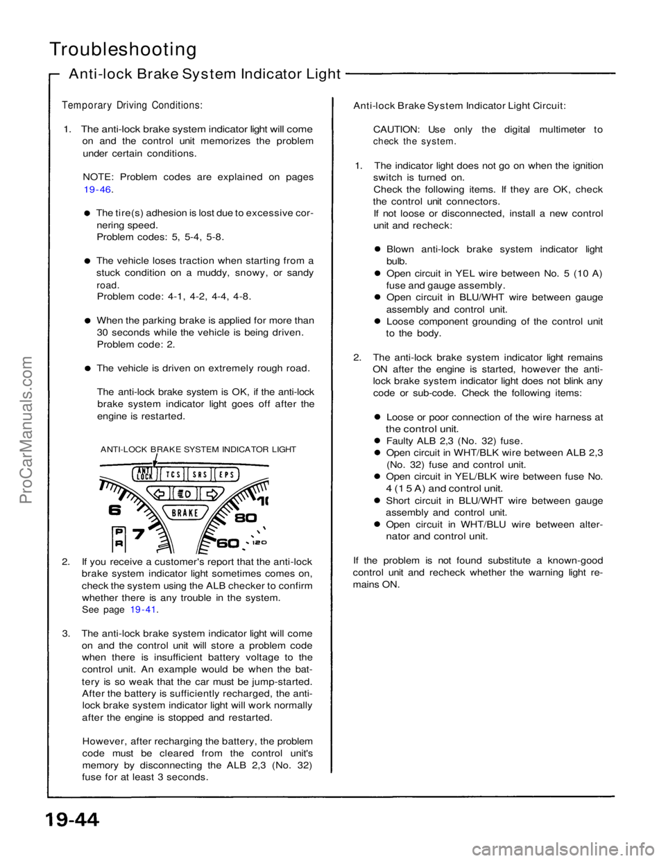
The anti-lock brake system is OK, if the anti-lock brake system indicator light goes off after the
engine is restarted.
ANTI-LOCK BRAKE SYSTEM INDICATOR LIGHT
2. If you receive a customer's report that the anti-lock brake system indicator light sometimes comes on,
check the system using the ALB checker to confirm
whether there is any trouble in the system.
See page 19 - 41.
3. The anti-lock brake system indicator light will come on and the control unit will store a problem codewhen there is insufficient battery voltage to the
control unit. An example would be when the bat-
tery is so weak that the car must be jump-started. After the battery is sufficiently recharged, the anti-lock brake system indicator light will work normally
after the engine is stopped and restarted.
However, after recharging the battery, the problem
code must be cleared from the control unit's
memory by disconnecting the ALB 2,3 (No. 32)
fuse for at least 3 seconds. Anti-lock Brake System Indicator Light Circuit:
CAUTION: Use only the digital multimeter to
check the system.
1. The indicator light does not go on when the ignition switch is turned on.
Check the following items. If they are OK, check
the control unit connectors. If not loose or disconnected, install a new control
unit and recheck:
Blown anti-lock brake system indicator light
bulb.
Open circuit in YEL wire between No. 5 (10 A)
fuse and gauge assembly. Open circuit in BLU/WHT wire between gauge
assembly and control unit. Loose component grounding of the control unit
to the body.
2. The anti-lock brake system indicator light remains ON after the engine is started, however the anti-lock brake system indicator light does not blink any
code or sub-code. Check the following items:
Loose or poor connection of the wire harness at
the control unit.
Faulty ALB 2,3 (No. 32) fuse.
Open circuit in WHT/BLK wire between ALB 2,3(No. 32) fuse and control unit.
Open circuit in YEL/BLK wire between fuse No.
4 (1 5 A) and control unit.
Short circuit in BLU/WHT wire between gauge
assembly and control unit. Open circuit in WHT/BLU wire between alter-
nator and control unit.
If the problem is not found substitute a known-good
control unit and recheck whether the warning light re-
mains ON.ProCarManuals.com