1991 ACURA NSX display
[x] Cancel search: displayPage 517 of 1640
Anti-lock Brake System (ABS) Description
Features/Construction/Operation
General
In a conventional brake system, if the brake pedal is depressed excessively, the wheels can lock before the vehicle
comes to a stop. In such a case, the stability of the vehicle is reduced if the rear wheels are locked, and maneuverabily of
the vehicle is reduced if the front wheels are locked, creating an extremely unstable condition.
The Anti-lock Brake System (ABS) modulates the pressure of the brake fluid applied to each caliper, thereby preventing
the locking of the wheels, whenever the wheels are likely to be locked due to excessive braking. It then restores normal
hydraulic pressure when there is no longer any possibility of wheel locking.
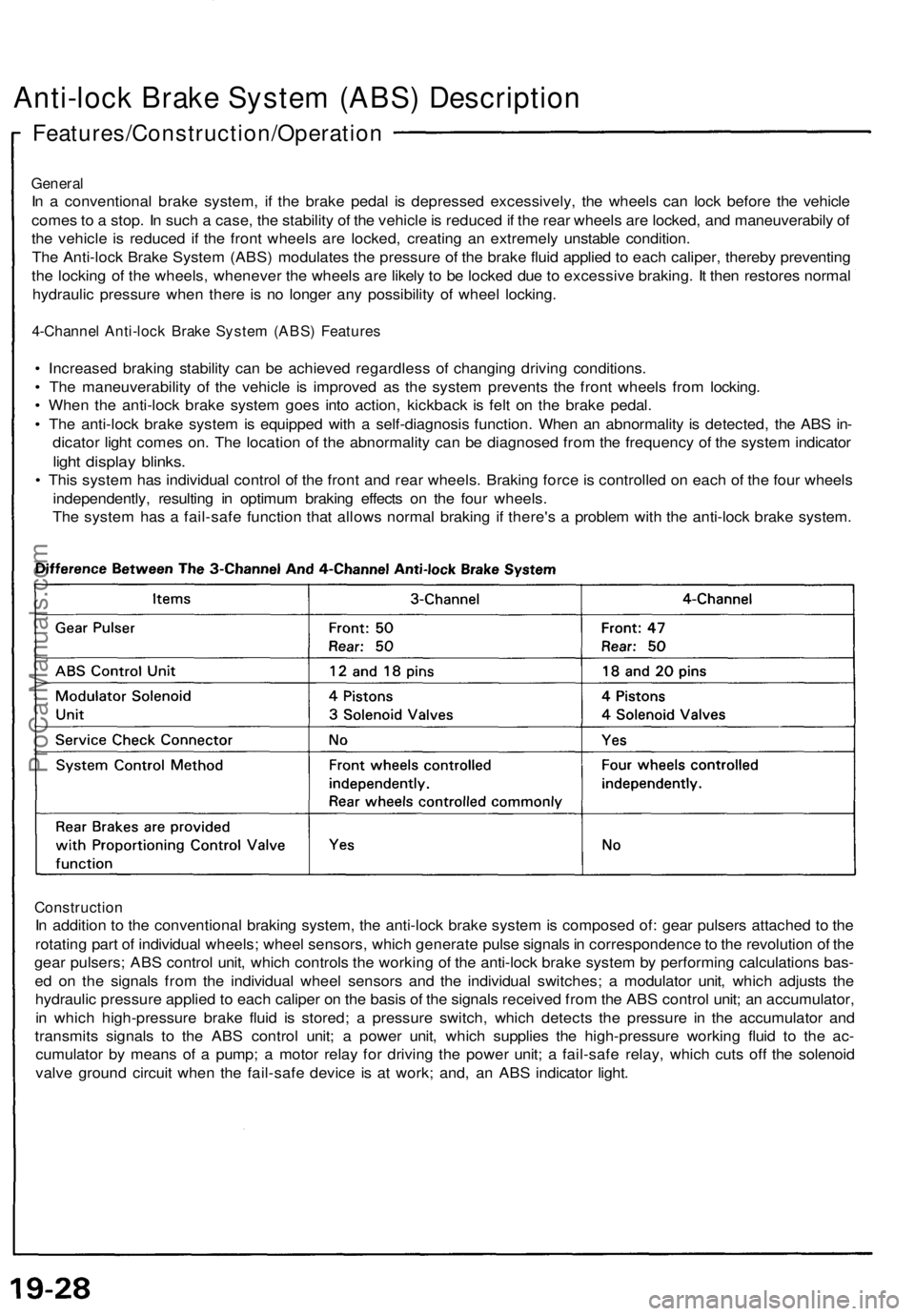
4-Channel Anti-lock Brake System (ABS) Features
• Increased braking stability can be achieved regardless of changing driving conditions.
• The maneuverability of the vehicle is improved as the system prevents the front wheels from locking.
• When the anti-lock brake system goes into action, kickback is felt on the brake pedal.
• The anti-lock brake system is equipped with a self-diagnosis function. When an abnormality is detected, the ABS in-
dicator light comes on. The location of the abnormality can be diagnosed from the frequency of the system indicator
light display blinks.
• This system has individual control of the front and rear wheels. Braking force is controlled on each of the four wheels
independently, resulting in optimum braking effects on the four wheels.
The system has a fail-safe function that allows normal braking if there's a problem with the anti-lock brake system.
Construction
In addition to the conventional braking system, the anti-lock brake system is composed of: gear pulsers attached to the
rotating part of individual wheels; wheel sensors, which generate pulse signals in correspondence to the revolution of the
gear pulsers; ABS control unit, which controls the working of the anti-lock brake system by performing calculations bas-
ed on the signals from the individual wheel sensors and the individual switches; a modulator unit, which adjusts the
hydraulic pressure applied to each caliper on the basis of the signals received from the ABS control unit; an accumulator,
in which high-pressure brake fluid is stored; a pressure switch, which detects the pressure in the accumulator and
transmits signals to the ABS control unit; a power unit, which supplies the high-pressure working fluid to the ac-
cumulator by means of a pump; a motor relay for driving the power unit; a fail-safe relay, which cuts off the solenoid
valve ground circuit when the fail-safe device is at work; and, an ABS indicator light.ProCarManuals.com
Page 685 of 1640
Troubleshooting
Self-diagnosis Circuit Check
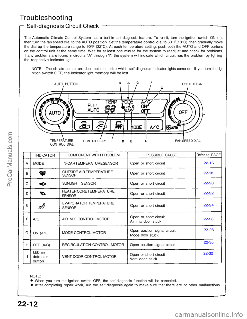
The Automatic Climate Control System has a built-in self diagnosis feature. To run it, turn the ignition switch ON (II),
then turn the fan speed dial to the AUTO position. Set the temperature control dial to 60° F(18°C), then gradually move
0
th
e
dial up the temperature range to 90°F (32°C). At each temperatu\
re setting, push both the AUTO and OFF burtons
o
n
the control unit at the same time. Wait for at least one minute for the\
system to readjust and check for problems.
If any problems are found in circuits "A" through "I", the system will indicate which circuit has the problem by lighting
the respective indicator light.
NOTE: The climate control unit does not memorize which self-diagnosis indicator lights come on. If you turn the ig-
nition switch OFF, the indicator light memory will be lost.
AUTO BUTTON
OFF BUTTON
TEMPERATURE CONTROL DIAL
TEMP DISPLAY
FAN SPEED DIAL
NOTE:
When you turn the ignition switch OFF, the self-diagnosis function will be canceled. After completing repair work, run the self-diagnosis again to make sure that there are no other malfunctions.COMPONENT WITH PROBLEM
IN-CAR TEMPERATURE SENSOR
OUTSIDE AIR TEMPERATURE
SENSOR
SUNLIGHT SENSOR
HEATER CORE TEMPERATURE
SENSOR
EVAPORATOR TEMPERATURE
SENSOR
AIR MIX CONTROL MOTOR
MODE CONTROL MOTOR
RECIRCULATION CONTROL MOTOR
VENT DOOR CONTROL MOTOR
POSSIBLE CAUSE
Open or short circuit
Open or short circuit
Open or short circuit
Open or short circuit
Open or short circuit
Open or short circuit
Air mix door stuck
Open position signal circuit
Mode door stuck
Open position signal circuit
Open or short circuit
Vent door stuck
Refer to PAGE
22-16
22-1
8
22-20
22-22
22-24
22-2
6
22-28
22-30
22-32
INDICATOR
MODE
A/C
ON
(A/C)
OFF
(A/C)
LED on
defroster
button
A
B
C
D
E
F
G
H
I
ProCarManuals.com
Page 691 of 1640
Adjustment
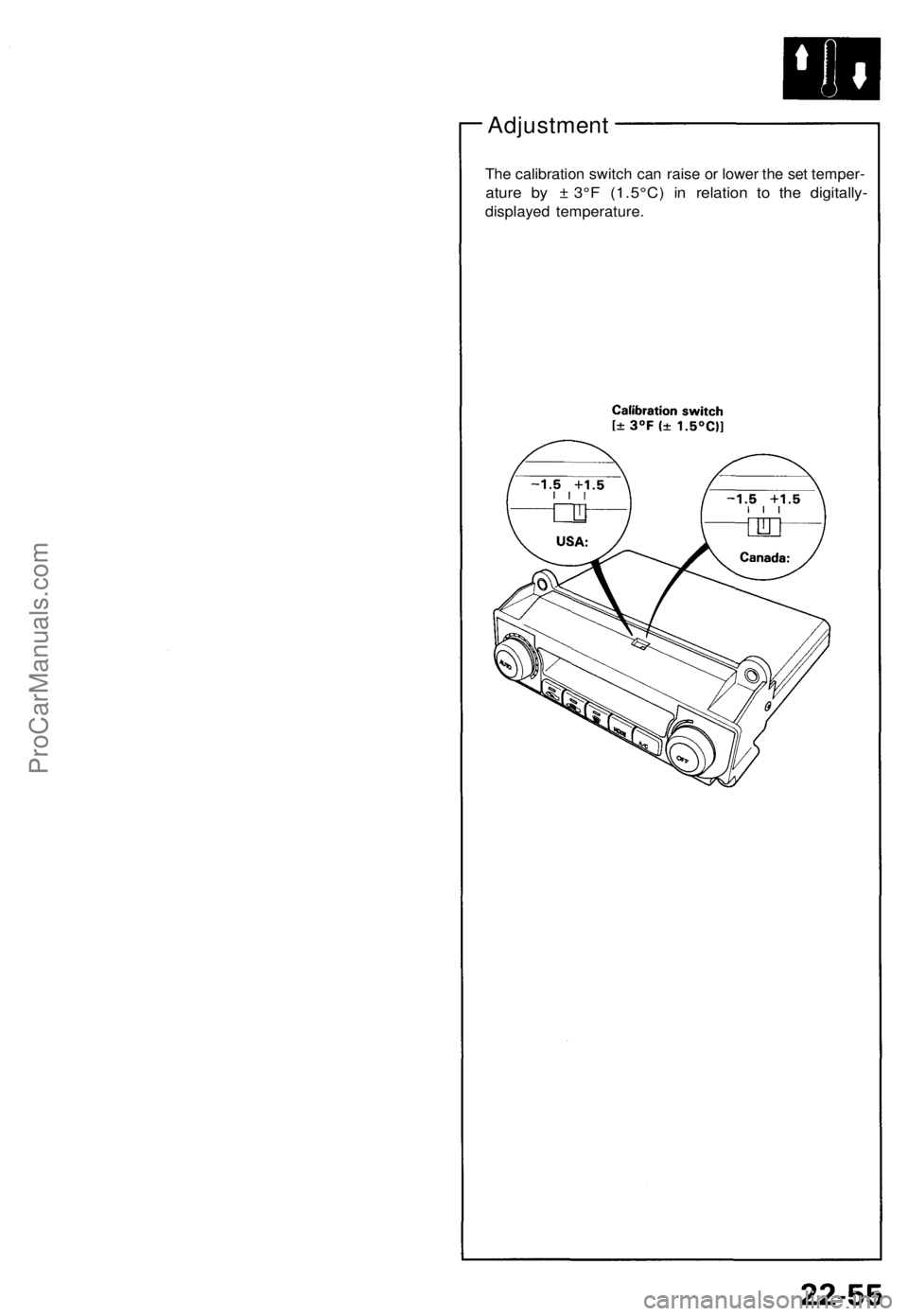
The calibratio n switc h can rais e o r lowe r th e se t temper -
ature b y ± 3° F (1.5°C ) i n relatio n t o th e digitally -
displayed temperature .
ProCarManuals.com
Page 1076 of 1640
Troubleshooting
Troubleshooting Guide
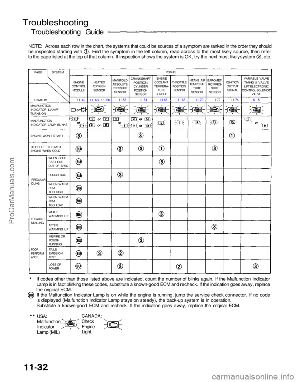
NOTE: Across each row in the chart, the systems that could be sources of a symptom are ranked in the order they should be inspected starting with . Find the symptom in the left column, read across to the most likely source, then refer
to the page listed at the top of that column. If inspection shows the system is OK, try the next most likely system , etc.
If codes other than those listed above are indicated, count the number of blinks again. If the Malfunction Indicator
Lamp is in fact blinking these codes, substitute a known-good ECM and recheck. If the indication goes away, replace
the original ECM.
If the Malfunction Indicator Lamp is on while the engine is running, jump the service check connector. If no code
is displayed (Malfunction Indicator Lamp stays on steady), the back-up system is in operation.
Substitute a known-good ECM and recheck. If the indication goes away, replace the original ECM.
USA:
Malfunction
Indicator
Lamp (MIL)
CANADA:
Check
Engine
Light
PAGE
SYSTEM
SYMTOM
MALFUNCTION INDICATOR
LAMP"
TURNS ON
MALFUNCTION
INDICATOR LAMP BLINKS
ENGINE WON'T START
DIFFICULT TO START
ENGINE WHEN COLD
WHEN COLDFAST IDLE
OUT OF SPEC
IRREGULAR
IDLING
ROUGH IDLE
WHEN WARM
RPM
TOO HIGH
WHEN WARM
RPM
TOO LOW
WHILE
WARMING UP
FREQUENT
STALLING
AFTER
WARMING UP
MISFIRE OR
ROUGH
RUNNING
POOR
PERFORM-
ANCE
FAILS
EMISSION
TEST
LOSS OF
POWER
ENGINE
CONTROL
MODULE
11-42
HEATED
OXYGEN
SENSOR
11-48, 11-50
MANIFOLD
ABSOLUTE
PRESSURE
SENSOR
11-58
CRANKSHAFT
POSITION/
CYLINDER
POSITION
SENSOR
11-64
PGM-FI
ENGINE
COOLANT
TEMPERA-
TURE
SENSOR
THROTTLE
POSITION
SENSOR
INTAKE AIR
TEMPERA-
TURE
SENSOR
BAROMET-
RIC PRES-
SURE
SENSOR
IGNITION
OUTPUT
SIGNAL
VARIABLE VALVE
TIMING & VALVE
LIFT ELECTRONIC
CONTROL SOLENOID
VALVE
6-15
11-74
11-72
11-70
11-68
11-66
ProCarManuals.com
Page 1211 of 1640
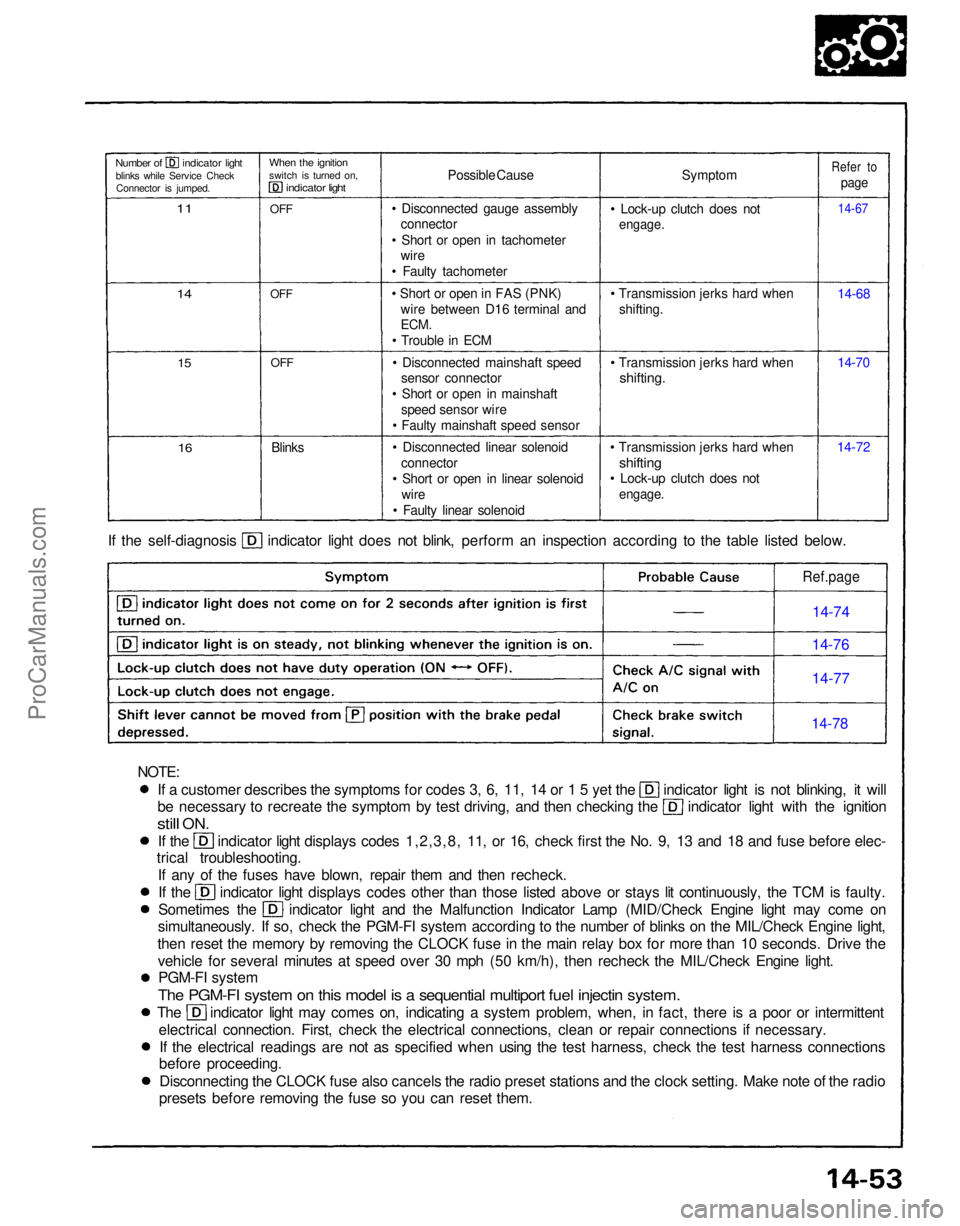
If a customer describes the symptoms for codes 3, 6, 11, 14 or 1 5 yet the indicator light is not blinking, it will
be necessary to recreate the symptom by test driving, and then checking the indicator light with the ignition
still
ON.
If the indicator light displays codes 1,2,3,8, 11, or 16, check first the No. 9, 13 and 18 and fuse before elec-
trical troubleshooting.
If any of the fuses have blown, repair them and then recheck. If the indicator light displays codes other than those listed above or stays lit continuously, the TCM is faulty.
Sometimes the indicator light and the Malfunction Indicator Lamp (MID/Check Engine light may come on
simultaneously. If so, check the PGM-FI system according to the number of blinks on the MIL/Check Engine light,
then reset the memory by removing the CLOCK fuse in the main relay box for more than 10 seconds. Drive the vehicle for several minutes at speed over 30 mph (50 km/h), then recheck the MIL/Check Engine light.PGM-FI system
The PGM-FI system on this model is a sequential multiport fuel injectin system.
The indicator light may comes on, indicating a system problem, when, in fact, there is a poor or intermittent
electrical connection. First, check the electrical connections, clean or repair connections if necessary.If the electrical readings are not as specified when using the test harness, check the test harness connections
before proceeding.
Disconnecting the CLOCK fuse also cancels the radio preset stations and the clock setting. Make note of the radio
presets before removing the fuse so you can reset them. If the self-diagnosis indicator light does not blink, perform an inspection according to the table listed below.
Symptom
• Lock-up clutch does not
engage.
• Transmission jerks hard when shifting.
• Transmission jerks hard when
shifting.
• Transmission jerks hard when
shifting
• Lock-up clutch does not
engage.
14-7214-70 14-68
14-67
Refer to
page
Possible Cause
• Disconnected gauge assembly connector
• Short or open in tachometer wire
• Faulty tachometer
• Short or open in FAS (PNK) wire between D16 terminal and
ECM.
• Trouble in ECM
• Disconnected mainshaft speed sensor connector
• Short or open in mainshaft speed sensor wire
• Faulty mainshaft speed sensor
• Disconnected linear solenoid connector
• Short or open in linear solenoid wire
• Faulty linear solenoid
Blinks
OFF
OFF
OFF
When the ignition
switch is turned on,
indicator light
Number of indicator light
blinks while Service CheckConnector is jumped.
11
14
15
16
Ref.page
14-74
14-76
14-77
14-78
NOTE:ProCarManuals.com
Page 1336 of 1640
Troubleshooting
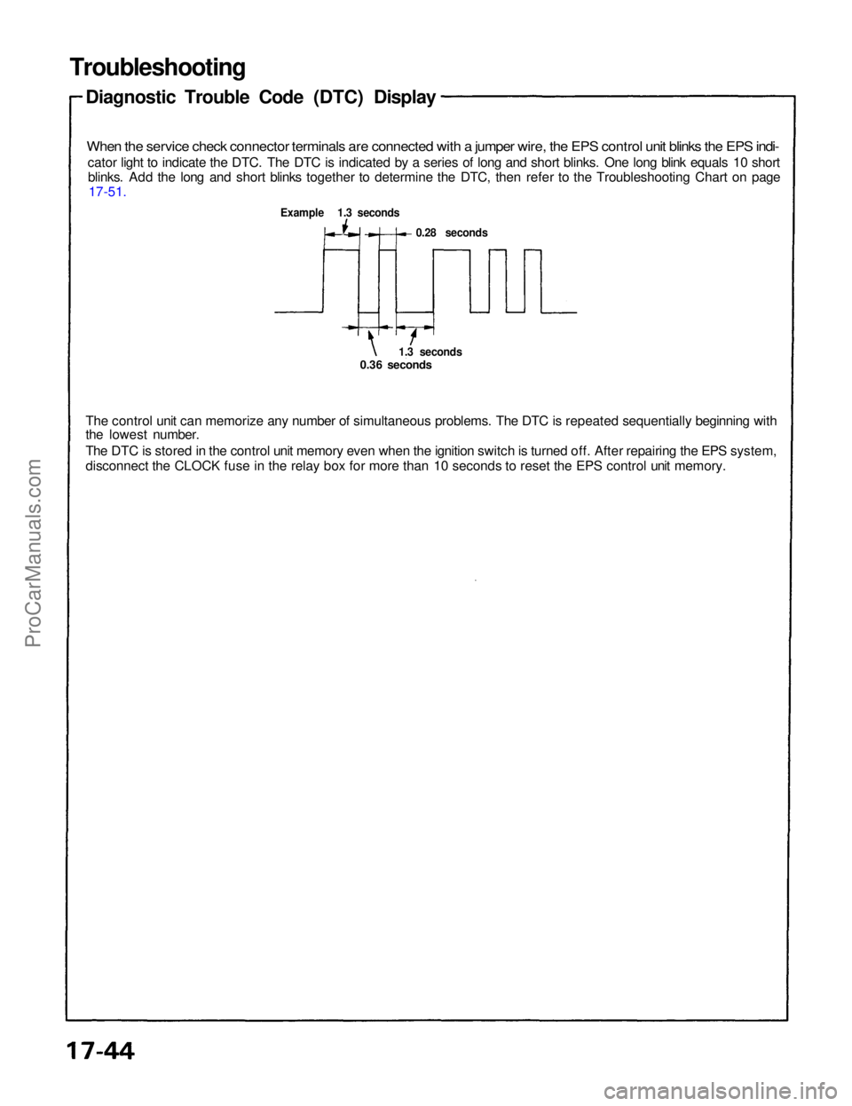
Diagnostic Trouble Code (DTC) Display
When the service check connector terminals are connected with a jumper wire, the EPS control unit blinks the EPS indi-
cator light to indicate the DTC. The DTC is indicated by a series of long and short blinks. One long blink equals 10 shortblinks. Add the long and short blinks together to determine the DTC, then refer to the Troubleshooting Chart on page 17-51.
Example 1.3 seconds
0.28 seconds
1.3 seconds
0.36 seconds
The control unit can memorize any number of simultaneous problems. The DTC is repeated sequentially beginning with
the lowest number.
The DTC is stored in the control unit memory even when the ignition switch is turned off. After repairing the EPS system,
disconnect the CLOCK fuse in the relay box for more than 10 seconds to reset the EPS control unit memory.ProCarManuals.com
Page 1477 of 1640
Troubleshooting
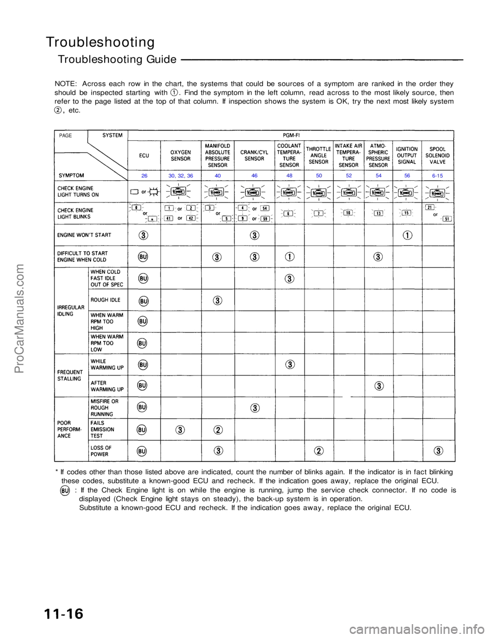
Troubleshooting Guide
NOTE: Across each row in the chart, the systems that could be sources of a symptom are ranked in the order they should be inspected starting with . Find the symptom in the left column, read across to the most likely source, then
refer to the page listed at the top of that column. If inspection shows the system is OK, try the next most likely system
,
etc.
* If codes other than those listed above are indicated, count the number of blinks again. If the indicator is in fact blinking these codes, substitute a known-good ECU and recheck. If the indication goes away, replace the original ECU. : If the Check Engine light is on while the engine is running, jump the service check connector. If no code is
displayed (Check Engine light stays on steady), the back-up system is in operation.
Substitute a known-good ECU and recheck. If the indication goes away, replace the original ECU.
PAGE
26
30, 32, 36
40
46
48
50
52
54
56
6-15ProCarManuals.com