1991 ACURA NSX reset
[x] Cancel search: resetPage 121 of 1640

Cylinder Head s
Installatio n
Rear:
8 x 1.2 5 mm22 N- m (2. 2 kg-m ,16 Ib-ft ) REA
R PRIMAR Y
HO2S45 N- m (4. 5 kg-m ,33 Ib-ft )
B e carefu l no t t o damage .
GASKE T
Replace .
REA R EXHAUS T
MANIFOLD
EXHAUSTMANIFOL DCOVER
SELF-LOCKIN G NU T8 x 1.2 5 mm34 N- m (3. 4 kg-m ,25 Ib-ft )Replace .
Install th e cylinde r head s o n th e engin e block .
Th e cylinde r hea d dowe l pin s an d th e hea d oi l con -
tro l orific e mus t b e aligned .
• Alway s us e a ne w cylinde r hea d gasket .
• Clea n th e oi l contro l orific e befor e installing .
CYLINDE R HEA D OI L CONTRO L CYLINDE R HEA D
GASKE T ORIFICE S GASKE T
Replace . Clean . Replace .
DOWE L PI N DOWE
L
PIN S
O-RIN G
Replace .
4. Tighte n th e cylinde r hea d bolt s sequentiall y i n tw o
o r thre e steps .
• Appl y clea n engin e oi l t o th e bol t thread s an d
washe r contac t surfaces .
Specifie d Torqu e
11 x 1. 5 m m
78 N- m (7. 8 kg-m , 5 6 Ib-ft )
NOTE : W e recommen d usin g a beam-typ e torqu e
wrench . Whe n usin g a preset-typ e torqu e wrench ,
b e sur e t o tighte n slowl y an d no t t o over-tighten .
CYLINDE R HEA D BOLT S TORQU E SEQUENC E
CYLINDER HEA D BOL T11 x 1. 5 m m78 N- m (7. 8 kg-m , 5 6 Ib-ft )Apply clea n engin e oi l t o th ebolt thread s an d washe r contac tsurfaces .
ProCarManuals.com
Page 208 of 1640
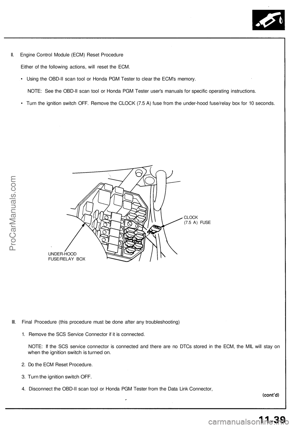
II. Engine Control Module (ECM) Reset Procedure
Either of the following actions, will reset the ECM.
• Using the OBD-II scan tool or Honda PGM Tester to clear the ECM's memory.
NOTE: See the OBD-II scan tool or Honda PGM Tester user's manuals for specific operating instructions.
• Turn the ignition switch OFF. Remove the CLOCK (7.5 A) fuse from the under-hood fuse/relay box for 10 seconds.
UNDER-HOOD
FUSE/RELAY BOX
CLOCK
(7.5 A) FUSE
III. Final Procedure (this procedure must be done after any troubleshooting)
1. Remove the SCS Service Connector if it is connected.
NOTE: If the SCS service connector is connected and there are no DTCs stored in the ECM, the MIL will stay on
when the ignition switch is turned on.
2. Do the ECM Reset Procedure.
3. Turn the ignition switch OFF.
4. Disconnect the OBD-II scan tool or Honda PGM Tester from the Data Link Connector,ProCarManuals.com
Page 358 of 1640

Preset Torqu e
Inspectio n
On-Car:
1 . Bloc k th e fron t wheels .
2 . Shif t t o low gear .
3 . Lif t u p rea r wheels , an d plac e th e safet y stan d (Lif t
an d Suppor t Points , se e sectio n 1 ).
4 . Measur e prese t torqu e clockwis e usin g a torqu e
wrenc h a s shown .
Standard: 120-280 N-m (12-28 kg-m,
87-20 3 Ib-ft )
Servic e Limit : 6 0 N- m (6 kg-m , 4 3 Ib-ft )
TORQU E WRENC H
RIGH T REA R WHEE L
SAFETY STAN D
5. I f prese t torqu e is les s tha n th e servic e limit , replac e
th e limite d sli p differentia l clutc h set .
NOTE : Adjus t th e 6 5 m m (differentia l housin g cove r
side ) an d 11 2 m m (differentia l housin g cove r side )
shim s wheneve r th e clutc h se t i s replaced . Assembly
:
Plac e on e specia l too l i n a vise . Plac e th e lef t sid e
o f th e differentia l assembl y o n th e specia l tool , the n
prese t th e differentia l wit h 3- 5 rotations , counter -
clockwise .
DIFFERENTIA L
INSPECTIO N TOOL S
07MAJ-PR90100
2. Measur e prese t torqu e counterclockwis e usin g a tor -
qu e wrenc h a s shown.
Standard :
60-140 N- m (6-1 4 kg-m ,
43-10 1 Ib-ft )
Servic e Limit : 3 0 N- m (3 kg-m , 2 2 Ib-ft )
TORQU E WRENC H
DIFFERENTIA L
INSPECTIO N TOOL S
07MAJ-PR90100
3 . I f prese t torqu e is les s tha n th e servic e limit , replac e
th e limite d sli p differentia l clutc h set .
NOTE : Adjus t th e 6 5 m m an d 11 2 m m shim s
wheneve r th e clutc h se t i s replaced .
ProCarManuals.com
Page 367 of 1640
I
Oil Seal
Removal
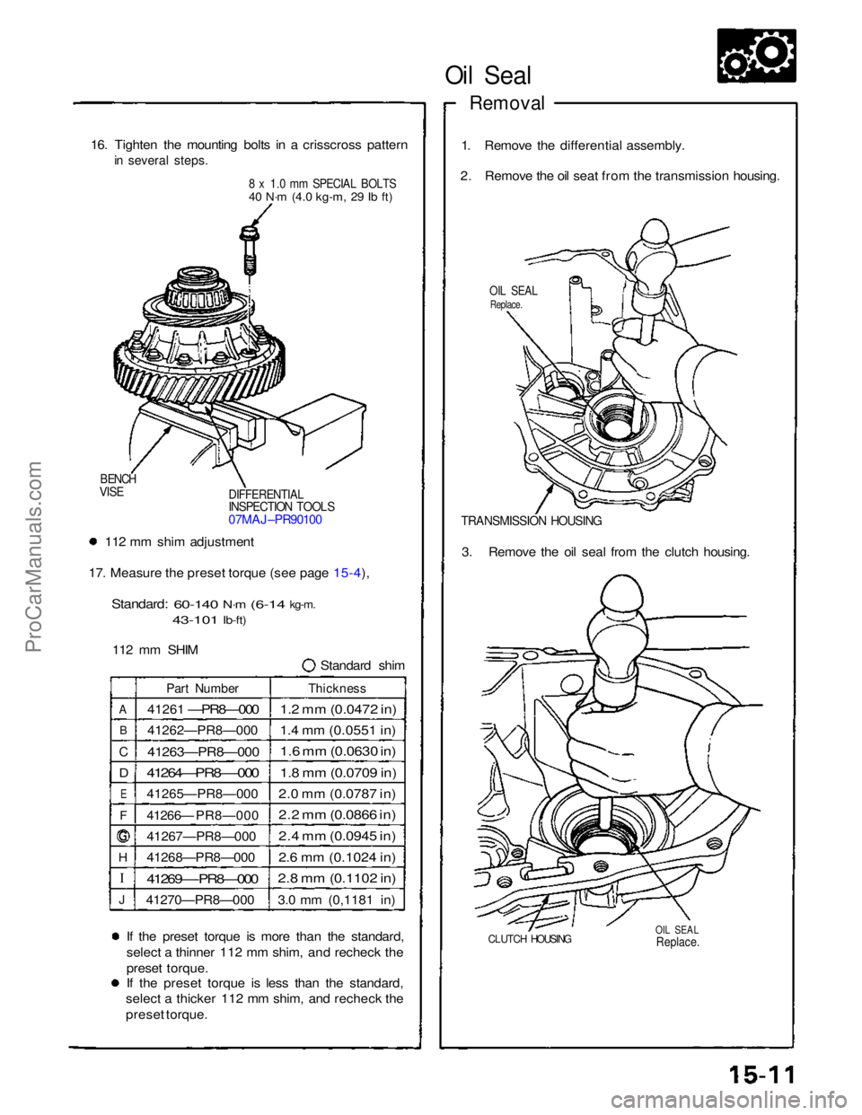
16. Tighten the mounting bolts in a crisscross pattern
in several steps.
8 x 1.0 mm SPECIAL BOLTS
40 N·m
(4.0 kg-m,
29 Ib ft)
1. Remove the differential assembly.
2. Remove the oil seat from the transmission housing.
OIL SEAL
Replace.
DIFFERENTIAL
INSPECTION TOOLS
07MAJ–PR90100
BENCH
VISE
TRANSMISSION HOUSING
112 mm shim adjustment
17. Measure the preset torque (see page 15-4),
Standard:
60-140
N·m
(6-14
kg-m.
43-101
Ib-ft)
112 mm SHIM Standard shim3. Remove the oil seal from the clutch housing.
A
B
C
D
E
F
H
J
Part Number
41261
—PR8—000
41262—PR8—000
41263—PR8—000
41264—PR8—-000
41265—PR8—000
41266— PR8—000
41267—PR8—000
41268—PR8—000
41269—-PR8—000
41270—PR8—000
Thickness
1.2 mm (0.0472 in)
1.4 mm (0.0551 in)
1.6 mm (0.0630 in)
1.8 mm (0.0709 in)
2.0 mm (0.0787 in)
2.2 mm (0.0866 in)
2.4 mm (0.0945 in)
2.6 mm (0.1024 in)
2.8 mm (0.1102 in)
3.0 mm (0,1181 in)
If the preset torque is more than the standard,
select a thinner 112 mm shim, and recheck the
preset torque.
If the preset torque is less than the standard,
select a thicker 112 mm shim, and recheck the
preset torque.
CLUTCH HOUSING
OIL SEAL
Replace.
ProCarManuals.com
Page 373 of 1640
Preset Torque
Inspection
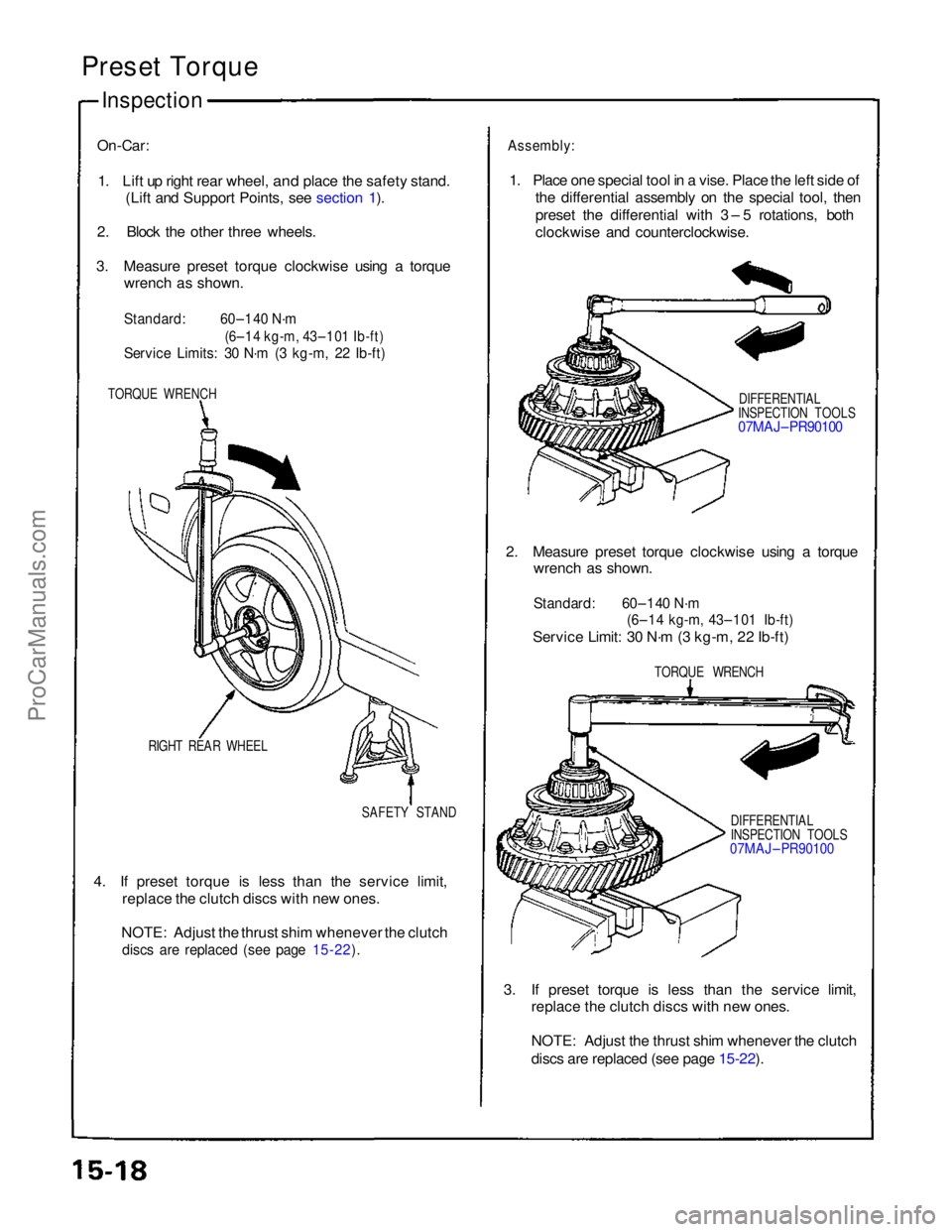
On-Car:
1. Lift up right rear wheel,
and place the safety stand.
(Lift and Support Points, see section 1).
2. Block the other three wheels.
3. Measure preset torque clockwise using a torque wrench as shown.
Standard:
60–140 N·m
(6–14 kg-m, 43–101 Ib-ft)
Service Limits: 30 N·m (3 kg-m, 22 Ib-ft)
TORQUE WRENCH
RIGHT REAR WHEEL SAFETY STAND
4. If preset torque is less than the service limit, replace the clutch discs with new ones.
NOTE: Adjust the thrust shim whenever the clutch
discs are replaced (see page 15-22).
Assembly:
1. Place one special tool in a vise. Place the left side of the differential assembly on the special tool, then
preset the differential with 3 – 5 rotations, both
clockwise and counterclockwise.
DIFFERENTIAL
INSPECTION TOOLS
07MAJ– PR90100
2. Measure preset torque clockwise using a torque wrench as shown.
Standard: 60–140 N·m
(6–14 kg-m, 43–101 Ib-ft)
Service Limit: 30 N·m (3 kg-m, 22 Ib-ft)
TORQUE WRENCH
DIFFERENTIAL
INSPECTION TOOLS
07MAJ – PR90100
3. If preset torque is less than the service limit, replace the clutch discs with new ones.
NOTE: Adjust the thrust shim whenever the clutch
discs are replaced (see page 15-22).
ProCarManuals.com
Page 377 of 1640
\
I
Clutch Disc, Clutch Plate
Replacement
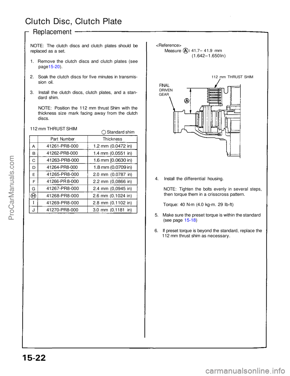
NOTE: The clutch discs and clutch plates should be
replaced as a set.
1. Remove the clutch discs and clutch plates (see
page15-20).
2. Soak the clutch discs for five minutes in transmis-
sion oil.
3. Install the clutch discs, clutch plates, and a stan- dard shim.
NOTE: Position the 112 mm thrust Shim with the
thickness size mark facing away from the clutch
discs.
112 mm THRUST SHIM
Standard shim
A
B
C
D
E
F
G
J
Part Number
41261-PR8-000
41262-PR8-000
41263-PR8-000
41264-PR8-000
41265-PR8-000
41266-PR
8-000
41267-PR8-000
41268-PR8-000
41269-PR8-000
41270-PR8-000
Thickness
1.2 mm (0.0472 in)
1.4 mm (0.0551 in)
1.6 mm [0.0630 in)
1.8 mm (0.0709 in)
2.0 mm (0.0787 in)
2.2 mm (0,0866 in)
2.4 mm (0,0945 in)
2.6 mm (0.1024 in)
2.8 mm (0.1102 in)
3.0 mm (0.1181 in)
Measure
41.7– 41.9
mm
(1.642 – 1.650 In)
112 mm THRUST SHIM
FINAL
DRIVEN
GEAR
4. Install the differential housing.
NOTE: Tighten the bolts evenly in several steps,
then torque them in a crisscross pattern.
Torque: 40 N·m (4.0 kg-m. 29 Ib-ft)
5. Make sure the preset torque is within the standard (see page 15-18)
6. If preset torque is beyond the standard, replace the 112 mm thrust shim as necessary.ProCarManuals.com
Page 420 of 1640
Troubleshooting Precautions
EPS Indicator Light
Under normal conditions, the EPS indicator light in the gauge assembly comes on when the ignition switch is turned to
the ON (II) position, then goes off after the engine is started. This indicates that the bulb and its circuits are operating cor-
rectly. If there is any trouble in the system, the EPS indicator light turns on during driving, and the power steering assist is
turned off. When the EPS indicator light comes on, the control unit memorizes the DTC. In this case, the control unit does
not activate the EPS system after the engine starts again but it keeps the EPS indicator light on.
Diagnostic Trouble Code (DTC)
• The lowest DTC is indicated first.
• The DTCs continue blinking until the ignition switch is turned off.
• The DTCs are erased from the control unit when the EPS control unit VBU power supply or connector is disconnected.
• The EPS system can be reset and the control unit's memory can be erased by disconnecting the CLOCK (7.5 A) fuse for
more than ten seconds.
Self-diagnosis:
The CPU (central processing unit) controls the following when it detects a problem during self-diagnosis:
1. Turns the EPS indicator light ON to alert the driver.
2. Power assist stops, and normal manual steering operation resumes (except DTC 21 and DTC 33).
3. The EPS control unit memorizes the diagnostic trouble code (DTC).
4. After the DTC is stored in the control unit, the CPU stops self-diagnosis.
Troubleshooting:
• Before starting the troubleshooting, clear the DTC by disconnecting the CLOCK (7.5 A) fuse for ten seconds or more,
and test-drive the car. Check that the symptom of the trouble appears again, and then troubleshoot. If the problem is an
intermittent problem, the system does not become active after the engine starts even though the problem is solved.
• When both EPS indicator light and A/T "D" indicator light come on, perform the A/T troubleshooting first.
• When the customer's reported problem cannot be verified in the car, ask the customer about the conditions when the
EPS indicator light came ON, then test-drive the car under those conditions, if possible. If the EPS indicator light does
not come ON during the test, check for loose connections or poor contacts at the connectors by wiggling the harness,
etc.
• The connector terminal numbers are viewed from the wire side for the female terminals and from the terminal side for
the male terminals.
• After the repair, test-drive the car and check that the EPS indicator light does not come ON again during the test. (Refer
to the Symptom-to-System Chart for diagnostic period.)ProCarManuals.com
Page 553 of 1640
Troubleshooting
TCS Indicato r Ligh t
Temporar y Drivin g Conditions :
1 . Th e TC S indicato r ligh t wil l com e o n an d th e contro l uni t memorize s th e Diagnosti c Troubl e Cod e (DTC ) unde r certai n
temporar y conditions :
• Th e spar e tir e is installed , o r a tir e o f th e imprope r siz e is installed .
• Th e tir e pressure s ar e no t correct .
2 . I f th e TC S indicato r ligh t doe s no t com e bac k o n afte r correctin g th e tir e o r tir e pressur e problem , th e TC S syste m is
OK .
3. Remov e th e CLOC K (7. 5 A ) fus e fo r a t leas t thre e second s to clea r th e DT C fro m th e TC S contro l uni t memory .
NOTE : Disconnectin g th e CLOC K fus e als o cancel s th e radi o prese t station s an d th e cloc k setting . Mak e not e o f th e
radi o preset s befor e removin g th e fus e s o yo u ca n rese t them .
TC S Diagnosti c Troubl e Cod e (DTC ) Indication :
1 . Sto p th e engine .
2 . Tur n th e ignitio n switc h O N (II) , an d confir m tha t th e TC S indicato r ligh t come s on .
3 . Tur n th e ignitio n switc h off .
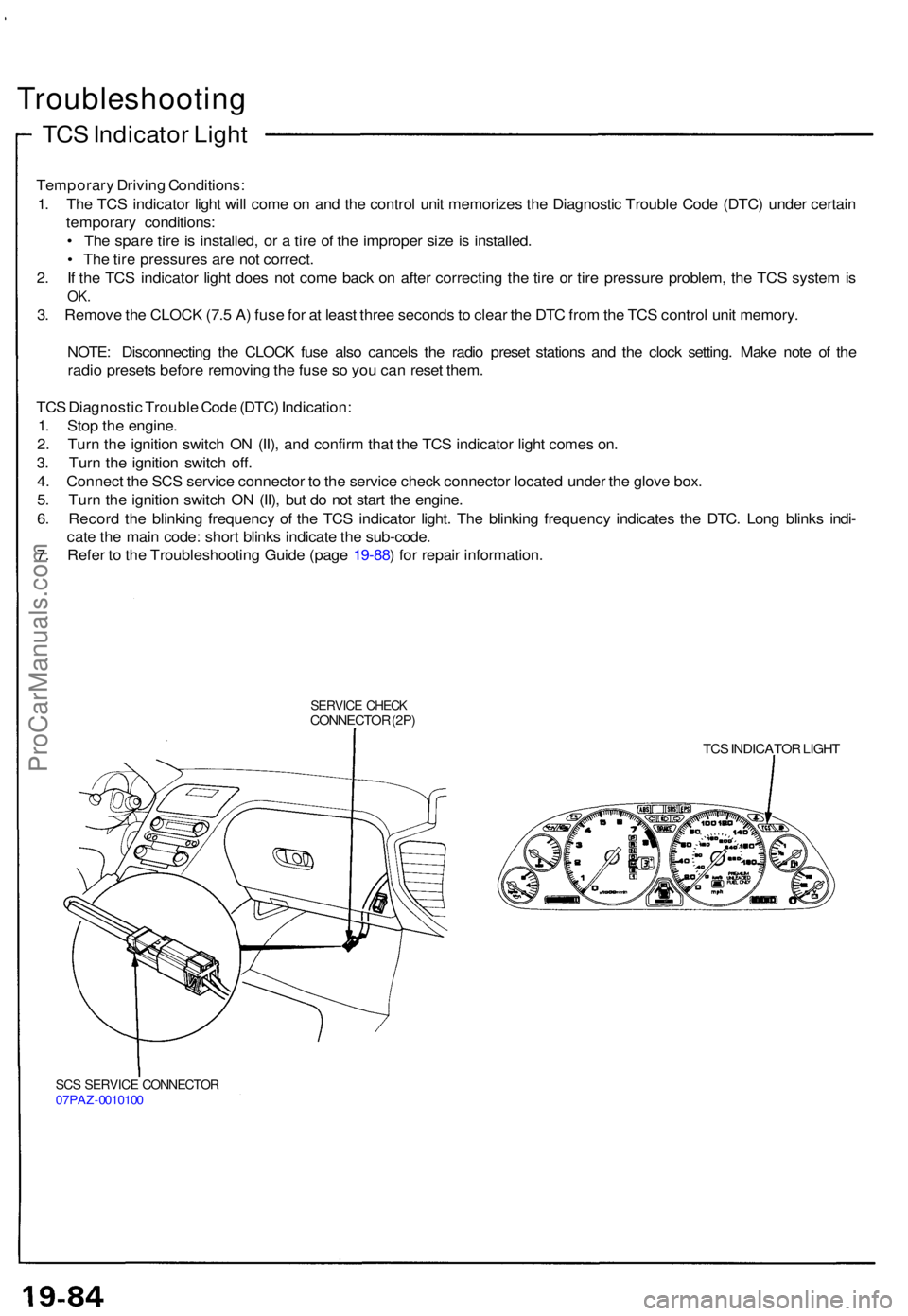
4 . Connec t th e SC S servic e connecto r t o th e servic e chec k connecto r locate d unde r th e glov e box .
5 . Tur n th e ignitio n switc h O N (II) , bu t d o no t star t th e engine .
6 . Recor d th e blinkin g frequenc y o f th e TC S indicato r light . Th e blinkin g frequenc y indicate s th e DTC . Lon g blink s indi -
cat e th e mai n code : shor t blink s indicat e th e sub-code .
7 . Refe r t o th e Troubleshootin g Guid e (pag e 19-88 ) fo r repai r information .
SERVICE CHEC KCONNECTO R (2P )
TCS INDICATO R LIGH T
SCS SERVIC E CONNECTO R07PAZ-001010 0
ProCarManuals.com