1991 ACURA NSX height
[x] Cancel search: heightPage 9 of 1640
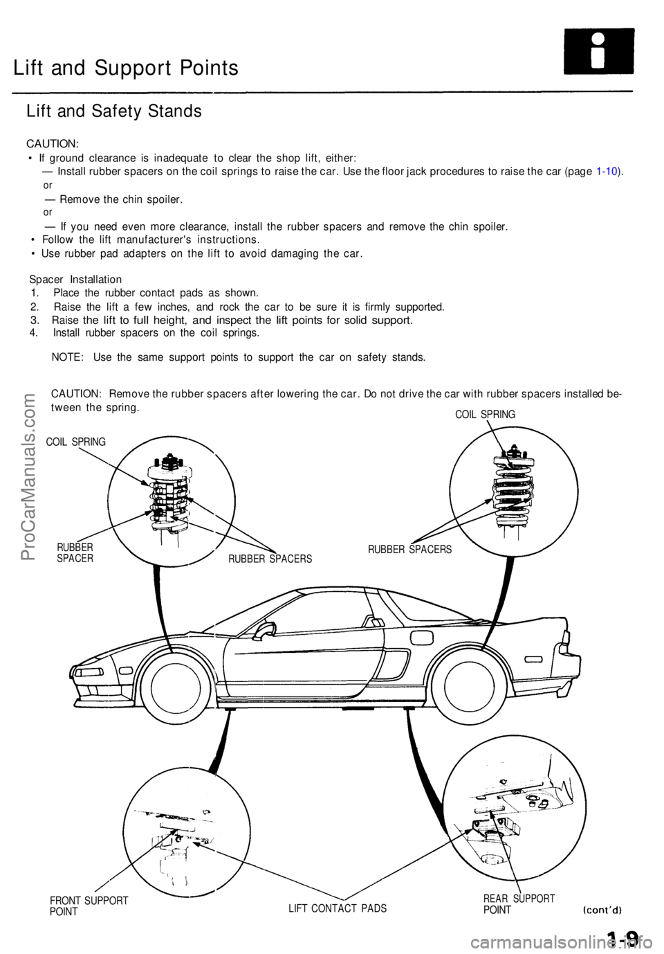
Lift an d Suppor t Point s
Lift an d Safet y Stand s
CAUTION :
• I f groun d clearanc e i s inadequat e t o clea r th e sho p lift , either :
— Instal l rubbe r spacer s o n th e coi l spring s t o rais e th e car . Us e th e floo r jac k procedure s t o rais e th e ca r (pag e 1-10 ).
o r
— Remov e th e chi n spoiler .
or
— If yo u nee d eve n mor e clearance , instal l th e rubbe r spacer s an d remov e th e chi n spoiler .
• Follo w th e lif t manufacturer' s instructions .
• Us e rubbe r pa d adapter s o n th e lif t t o avoi d damagin g th e car .
Space r Installatio n
1 . Plac e th e rubbe r contac t pad s a s shown .
2 . Rais e th e lif t a fe w inches , an d roc k th e ca r t o b e sur e i t i s firml y supported .
3. Rais e the lift to ful l height , and inspec t the lift point s for soli d support .
4. Instal l rubbe r spacer s o n th e coi l springs .
NOTE : Us e th e sam e suppor t point s t o suppor t th e ca r o n safet y stands .
CAUTION : Remov e th e rubbe r spacer s afte r lowerin g th e car . D o no t driv e th e ca r wit h rubbe r spacer s installe d be -
twee n th e spring .
COIL SPRIN G
COIL SPRIN G
RUBBE RSPACE R
FRONT SUPPOR TPOINTLIFT CONTAC T PAD SREAR SUPPOR TPOINT
RUBBE R SPACER SRUBBER SPACER S
ProCarManuals.com
Page 41 of 1640
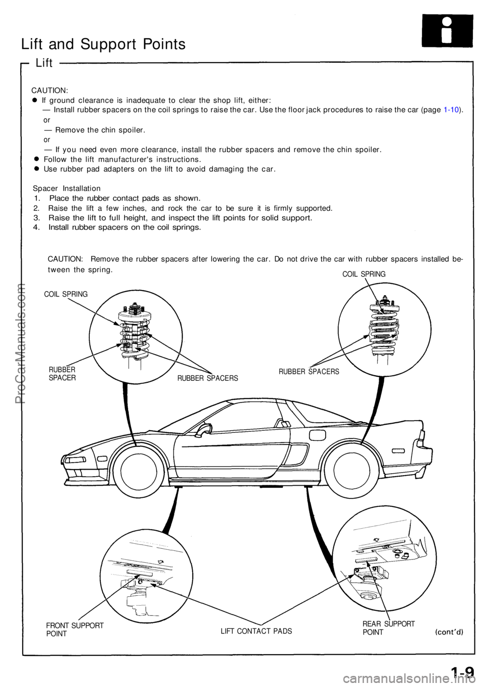
Lift an d Suppor t Point s
Lift
CAUTION :
I f groun d clearanc e i s inadequat e t o clea r th e sho p lift , either :
— Instal l rubbe r spacer s o n th e coi l spring s t o rais e th e car . Us e th e floo r jac k procedure s t o rais e th e ca r (pag e 1-10 ).
o r
— Remov e th e chi n spoiler .
or
— If yo u nee d eve n mor e clearance , instal l th e rubbe r spacer s an d remov e th e chi n spoiler .
Follo w th e lif t manufacturer' s instructions .
Us e rubbe r pa d adapter s o n th e lif t t o avoi d damagin g th e car .
Space r Installatio n
1. Plac e th e rubbe r contac t pad s a s shown .
2. Rais e th e lif t a fe w inches, and roc k th e ca r t o b e sur e i t i s firml y supported .
3. Rais e th e lif t t o ful l height , an d inspec t th e lif t point s fo r soli d support .
4. Instal l rubbe r spacer s o n th e coi l springs .
CAUTION : Remov e th e rubbe r spacer s afte r lowerin g th e car . D o no t driv e th e ca r wit h rubbe r spacer s installe d be -
twee n th e spring .
COIL SPRIN G
COIL SPRIN G
RUBBE RSPACER
FRONT SUPPOR TPOINTLIFT CONTAC T PAD SREAR SUPPOR TPOINT
RUBBE R SPACER SRUBBER SPACER S
ProCarManuals.com
Page 72 of 1640
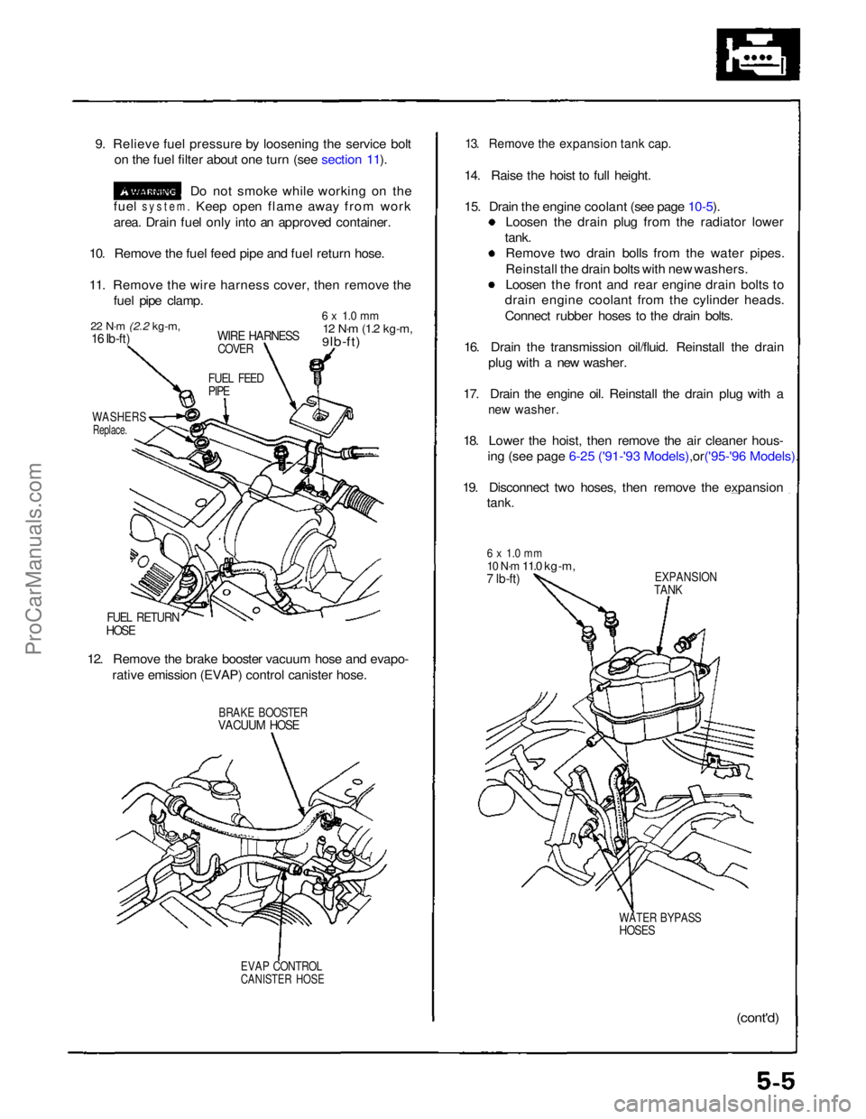
9. Relieve fuel pressure by loosening the service bolt
on the fuel filter about one turn (see section 11).
Do not smoke while working on the
fuel
system.
Keep open flame away from work
area. Drain fuel only into an approved container.
10. Remove the fuel feed pipe and fuel return hose.
11. Remove the wire harness cover, then remove the fuel pipe clamp.
22 N·m
(2.2 kg-m,
16 Ib-ft)
WIRE HARNESS
COVER
6 x 1.0 mm
12 N·m
(1.2 kg-m,
9 lb-ft)
FUEL FEED
PIPE
WASHERS
Replace.
FUEL RETURN
HOSE
12. Remove the brake booster vacuum hose and evapo- rative emission (EVAP) control canister hose.
BRAKE BOOSTER
VACUUM HOSE
EVAP CONTROL
CANISTER HOSE
13. Remove the expansion tank cap.
14. Raise the hoist to full height.
15. Drain the engine coolant (see page
10-5).
Loosen the drain plug from the radiator lower
tank. Remove two drain bolls from the water pipes.
Reinstall the drain bolts with new washers.
Loosen the front and rear engine drain bolts to
drain engine coolant from the cylinder heads.
Connect rubber hoses to the drain bolts.
16. Drain the transmission oil/fluid. Reinstall the drain plug with a new washer.
17. Drain the engine oil. Reinstall the drain plug with a
new washer.
18. Lower the hoist, then remove the air cleaner hous-
ing (see page 6-25 ('91-'93 Mode ls),or('95-'96 Models).
19. Disconnect two hoses, then remove the expansion
tank.
6 x 1.0 mm
10 N·m
11.0 kg-m,
7 lb-ft)
EXPANSION
TANK
WATER BYPASS
HOSES
(cont'd)ProCarManuals.com
Page 74 of 1640
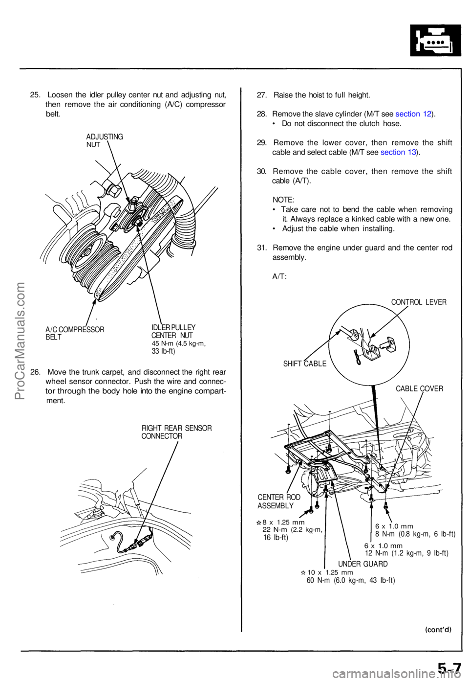
25. Loose n th e idle r pulle y cente r nu t an d adjustin g nut ,
the n remov e th e ai r conditionin g (A/C ) compresso r
belt.
ADJUSTIN GNUT
A/C COMPRESSO RBELT
IDLE R PULLE Y
CENTE R NU T
45 N- m (4. 5 kg-m ,33 Ib-ft )
26. Mov e th e trun k carpet , an d disconnec t th e righ t rea r
whee l senso r connector . Pus h th e wir e an d connec -
tor throug h th e bod y hol e int o th e engin e compart -
ment.
RIGH T REA R SENSO R
CONNECTO R
27. Rais e th e hois t t o ful l height .
28 . Remov e th e slav e cylinde r (M/ T se e sectio n 12 ).
• D o no t disconnec t th e clutc h hose .
29 . Remov e th e lowe r cover , the n remov e th e shif t
cabl e an d selec t cabl e (M/ T se e sectio n 13 ).
30 . Remov e th e cabl e cover , the n remov e th e shif t
cabl e (A/T) .
NOTE :
• Tak e car e no t t o ben d th e cabl e whe n removin g
it . Alway s replac e a kinke d cabl e wit h a ne w one .
• Adjus t th e cabl e whe n installing .
31 . Remov e th e engin e unde r guar d an d th e cente r ro d
assembly .
A/T:
CONTRO L LEVE R
CENTE R RO D
ASSEMBL Y
8 x 1.2 5 mm22 N- m (2. 2 kg-m ,16 Ib-ft )
6 x 1. 0 m m8 N- m (0. 8 kg-m , 6 Ib-ft )
6 x 1. 0 m m12 N- m (1. 2 kg-m , 9 Ib-ft )
UNDE R GUAR D
10 x 1.2 5 mm60 N- m (6. 0 kg-m , 4 3 Ib-ft )
SHIF
T CABL E
CABLE COVE R
ProCarManuals.com
Page 110 of 1640
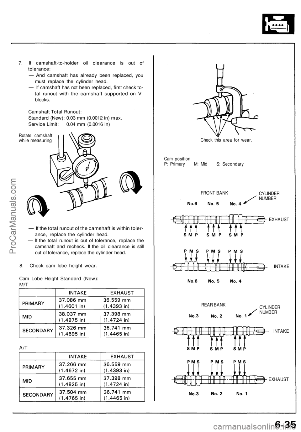
7. If camshaft-to-holder oil clearance is out of
tolerance:
— And camshaft has already been replaced, you
must replace the cylinder head.
— If camshaft has not been replaced, first check to-
tal runout with the camshaft supported on V-
blocks.
Camshaft Total Runout:
Standard (New): 0.03 mm (0.0012 in) max.
Service Limit: 0.04 mm (0.0016 in)
Rotate camshaft
while measuring
— If the total runout of the camshaft is within toler-
ance, replace the cylinder head.
— If the total runout is out of tolerance, replace the
camshaft and recheck. If the oil clearance is still
out of tolerance, replace the cylinder head.
8. Check cam lobe height wear.
Cam Lobe Height Standard (New):
M/T
A/T
Check this area for wear.
Cam position
P: Primary M: Mid S: Secondary
FRONT BANK
REAR BANK
CYLINDER
NUMBER
EXHAUST
INTAKE
CYLINDER
NUMBER
INTAKE
EXHAUSTProCarManuals.com
Page 114 of 1640
Valve Seat s
Reconditionin g
1. Rene w th e valv e seat s i n th e cylinde r hea d usin g a
valv e sea t grinder .
NOTE : I f guide s ar e wor n (se e pag e 6-39 ), replac e
the m (se e pag e 6-40 ) befor e grindin g th e valv e seats .
2 . Carefull y grin d a 45 ° seat , removin g onl y enoug h
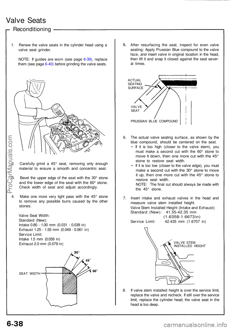
materia l t o ensur e a smoot h an d concentri c seat .
3 . Beve l th e uppe r edg e o f th e sea t wit h th e 30 ° ston e
and th e lowe r edg e of the sea t wit h th e 60 ° stone .
Check widt h o f sea t an d adjus t accordingly .
4 . Mak e on e mor e ver y ligh t pas s wit h th e 45 ° ston e
t o remov e an y possibl e burr s cause d b y th e othe r
stones .
Valv e Sea t Width :
Standar d (New) :
Intak e 0.8 0 - 1.0 0 m m (0.03 1 - 0.03 9 in )
Exhaus t 1.2 5 - 1.5 5 m m (0.04 9 - 0.06 1 in )
Servic e Limit :
Intak e 1. 5 m m (0.05 9 in )
Exhaus t 2. 0 m m (0.07 9 in )
SEA T WIDT H
After resurfacin g th e seat , inspec t fo r eve n valv e
seating : Appl y Prussia n Blu e compoun d t o th e valv e
face , an d inser t valv e in origina l locatio n in th e head ,
the n lif t i t an d sna p it close d agains t th e sea t sever -
a l times .
ACTUA L
SEATIN G
SURFAC E
VALVESEAT
PRUSSIA N BLU E COMPOUN D
6. Th e actua l valv e seatin g surface , a s show n b y th e
blu e compound , shoul d b e centere d o n th e seat .
• I f i t i s to o hig h (close r t o th e valv e stem) , yo u
mus t mak e a secon d cu t wit h th e 60 ° ston e t o
mov e it down , the n on e mor e cu t wit h th e 45 °
ston e t o restor e sea t width .
• I f i t i s to o lo w (close r t o th e valv e edge) , yo u mus t
make a secon d cu t wit h th e 30 ° ston e t o mov e
it up , the n on e mor e cu t wit h th e 45 ° ston e t o
restor e sea t width .
NOTE : Th e fina l cu t shoul d alway s b e mad e wit h
th e 45 ° stone .
7 . Inser t intak e an d exhaus t valve s i n th e hea d an d
measur e valv e ste m installe d height .
Valv e Ste m Installe d Heigh t (Intak e an d Exhaust) :
Standard (New) : 41.55-42.3 5 m m
(1.6358-1.667 3 in )
Servic e Limit : 42.43 5 m m (1.670 7 in )
VALV E STE M
INSTALLE D HEIGH T
8. I f valv e ste m installe d heigh t i s ove r th e servic e limit ,
replac e th e valv e an d recheck . I f stil l ove r th e servic e
limit , replac e th e cylinde r head ; th e valv e sea t i n th e
hea d is to o deep .
ProCarManuals.com
Page 169 of 1640
Thermostat
Replacemen t
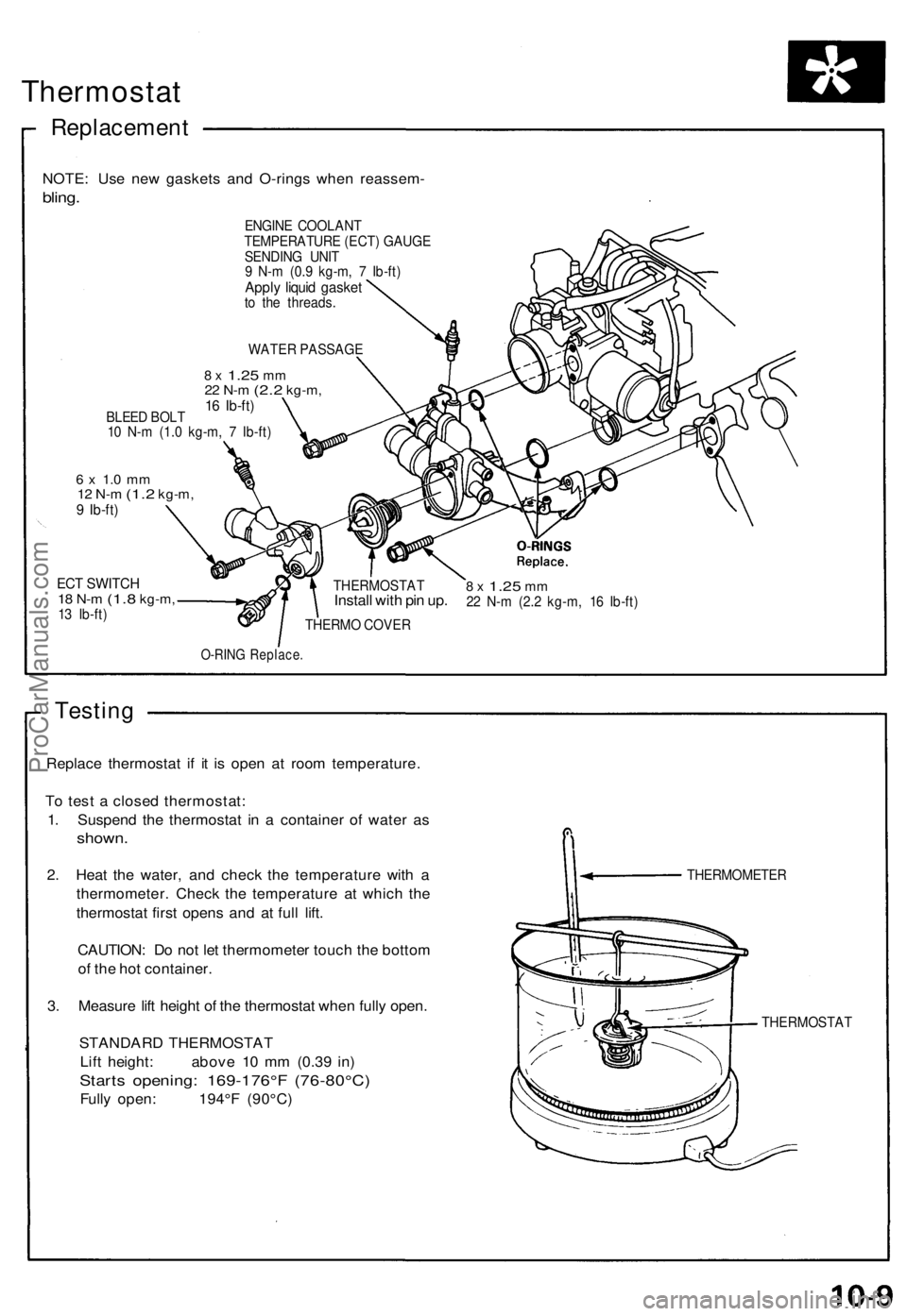
NOTE: Us e ne w gasket s an d O-ring s whe n reassem -
bling.
ENGIN E COOLAN T
TEMPERATUR E (ECT ) GAUG E
SENDIN G UNI T
9 N- m (0. 9 kg-m , 7 Ib-ft )
Apply liqui d gaske tto th e threads .
WATE R PASSAG E
8 x 1.2 5 mm22 N- m (2. 2 kg-m ,16 Ib-ft )BLEE D BOL T
1 0 N- m (1. 0 kg-m , 7 Ib-ft )
6 x 1. 0 m m12 N- m (1. 2 kg-m ,9 Ib-ft )
ECT SWITC H18 N- m (1. 8 kg-m ,13 Ib-ft )
8 x 1.2 5 mm22 N- m (2. 2 kg-m , 1 6 Ib-ft )
THERM O COVE R
O-RING Replace .
Testing
Replac e thermosta t i f i t i s ope n a t roo m temperature .
T o tes t a close d thermostat :
1 . Suspen d th e thermosta t i n a containe r o f wate r a s
shown .
2. Hea t th e water , an d chec k th e temperatur e wit h a
thermometer . Chec k th e temperatur e a t whic h th e
thermosta t firs t open s an d a t ful l lift .
CAUTION : D o no t le t thermomete r touc h th e botto m
o f th e ho t container .
3 . Measur e lif t heigh t o f th e thermosta t whe n full y open .
STANDAR D THERMOSTA T
Lif t height : abov e 1 0 m m (0.3 9 in )
Start s opening : 169-176° F (76-80°C )
Fully open : 194° F (90°C )
THERMOMETE R
THERMOSTA T
THERMOSTA
T
Install wit h pi n up .
ProCarManuals.com
Page 284 of 1640
Clutch Peda l
Adjustmen t
NOTE:
• T o chec k th e switch , se e sectio n 23 .
• Th e clutc h i s self-adjustin g t o compensat e fo r wear .
CAUTION : I f ther e i s n o clearanc e betwee n th e
maste r cylinde r pisto n an d pus h rod , th e releas e
bearin g is hel d agains t th e diaphrag m spring , whic h
ca n resul t i n clutc h slippag e o r othe r clutc h
problems .
1. Loose n locknu t A , an d bac k of f th e peda l switc h
until i t n o longe r touche s th e clutc h pedal .
2. Loose n locknu t C , an d tur n th e pus h ro d in o r ou t t o
ge t th e specifie d strok e an d heigh t a t th e clutc h
pedal.
3. Tighte n locknu t C .
4. Threa d in th e clutc h peda l switc h A in unti l i t con -
tacts th e clutc h pedal .
5. Tur n th e switc h in 1/ 4 — 1/2 tur n further .
6. Tighte n locknu t A .
7. Loose n locknu t B an d peda l switc h B .
8 . Measur e th e clearanc e betwee n th e floo r boar d an d
clutc h peda l wit h th e clutc h peda l full y depressed .
9. Releas e the clutc h peda l 15-20 m m (0.59-0.7 9
in) fro m th e full y depresse d position , an d hol d i t
there . Adjus t th e positio n o f peda l switc h B so tha t
the engin e wil l star t wit h th e clutc h peda l i n thi s
position .
10. Threa d in peda l switc h B in 1/ 4 — 1/2 tur n further .
11. Tighte n locknu t B .
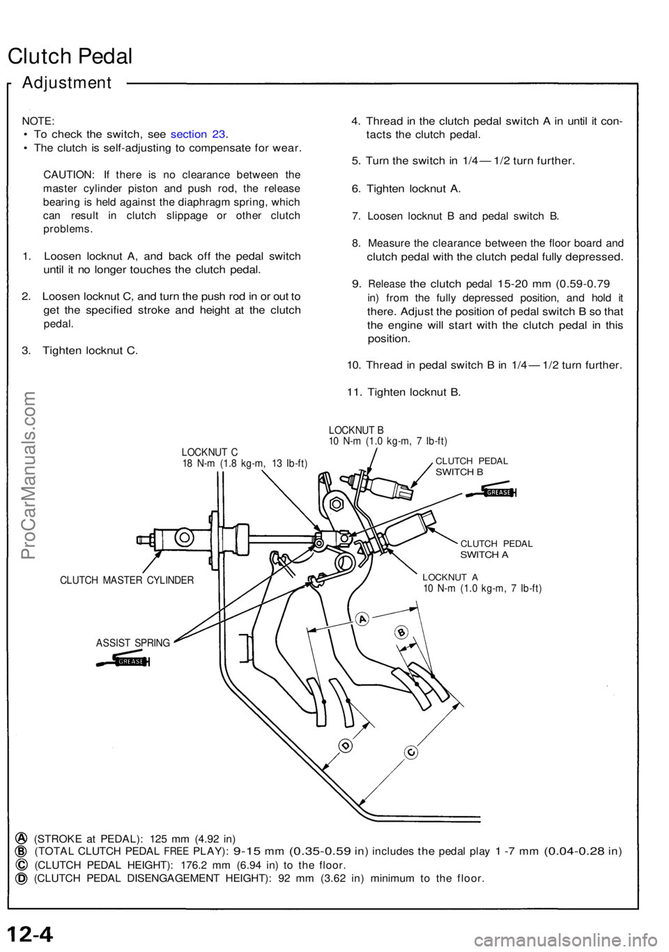
LOCKNU T C
1 8 N- m (1. 8 kg-m , 1 3 Ib-ft ) LOCKNU
T B
1 0 N- m (1. 0 kg-m , 7 Ib-ft )CLUTC H PEDA LSWITCH B
ASSIS T SPRIN G
CLUTCH PEDA LSWITCH A
LOCKNU T A10 N- m (1. 0 kg-m , 7 Ib-ft )
(STROK E a t PEDAL) : 12 5 m m (4.9 2 in )
(TOTA L CLUTC H PEDA L FREE PLAY) : 9-15 mm (0.35-0.5 9 in) include s the peda l pla y 1 -7 m m (0.04-0.2 8 in)
(CLUTC H PEDA L HEIGHT) : 176. 2 m m (6.9 4 in ) t o th e floor .
(CLUTC H PEDA L DISENGAGEMEN T HEIGHT) : 9 2 m m (3.6 2 in ) minimu m to th e floor .
CLUTC H MASTE R CYLINDE R
ProCarManuals.com