Page 367 of 1640
I
Oil Seal
Removal
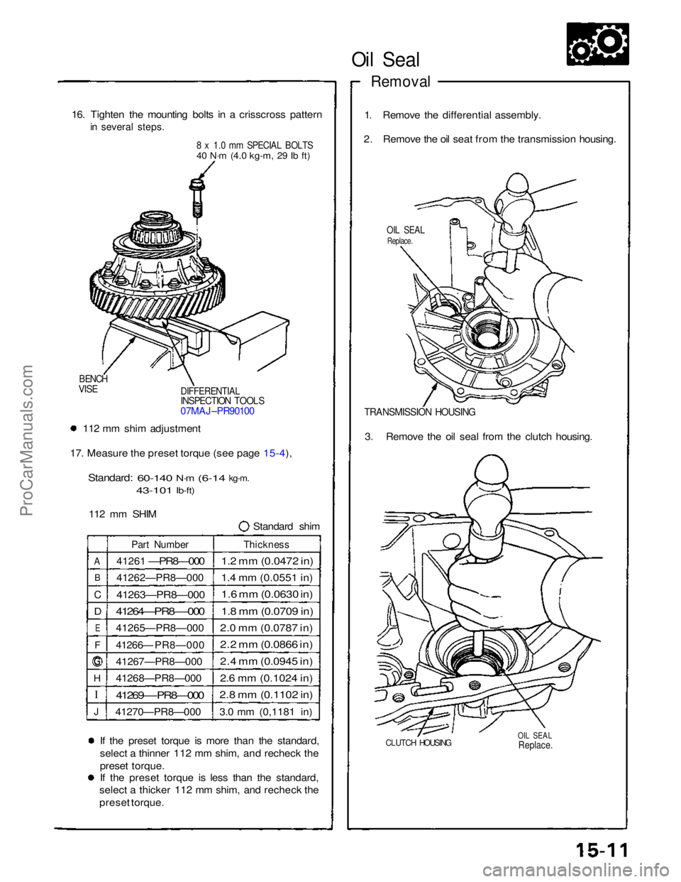
16. Tighten the mounting bolts in a crisscross pattern
in several steps.
8 x 1.0 mm SPECIAL BOLTS
40 N·m
(4.0 kg-m,
29 Ib ft)
1. Remove the differential assembly.
2. Remove the oil seat from the transmission housing.
OIL SEAL
Replace.
DIFFERENTIAL
INSPECTION TOOLS
07MAJ–PR90100
BENCH
VISE
TRANSMISSION HOUSING
112 mm shim adjustment
17. Measure the preset torque (see page 15-4),
Standard:
60-140
N·m
(6-14
kg-m.
43-101
Ib-ft)
112 mm SHIM Standard shim3. Remove the oil seal from the clutch housing.
A
B
C
D
E
F
H
J
Part Number
41261
—PR8—000
41262—PR8—000
41263—PR8—000
41264—PR8—-000
41265—PR8—000
41266— PR8—000
41267—PR8—000
41268—PR8—000
41269—-PR8—000
41270—PR8—000
Thickness
1.2 mm (0.0472 in)
1.4 mm (0.0551 in)
1.6 mm (0.0630 in)
1.8 mm (0.0709 in)
2.0 mm (0.0787 in)
2.2 mm (0.0866 in)
2.4 mm (0.0945 in)
2.6 mm (0.1024 in)
2.8 mm (0.1102 in)
3.0 mm (0,1181 in)
If the preset torque is more than the standard,
select a thinner 112 mm shim, and recheck the
preset torque.
If the preset torque is less than the standard,
select a thicker 112 mm shim, and recheck the
preset torque.
CLUTCH HOUSING
OIL SEAL
Replace.
ProCarManuals.com
Page 377 of 1640

\
I
Clutch Disc, Clutch Plate
Replacement
NOTE: The clutch discs and clutch plates should be
replaced as a set.
1. Remove the clutch discs and clutch plates (see
page15-20).
2. Soak the clutch discs for five minutes in transmis-
sion oil.
3. Install the clutch discs, clutch plates, and a stan- dard shim.
NOTE: Position the 112 mm thrust Shim with the
thickness size mark facing away from the clutch
discs.
112 mm THRUST SHIM
Standard shim
A
B
C
D
E
F
G
J
Part Number
41261-PR8-000
41262-PR8-000
41263-PR8-000
41264-PR8-000
41265-PR8-000
41266-PR
8-000
41267-PR8-000
41268-PR8-000
41269-PR8-000
41270-PR8-000
Thickness
1.2 mm (0.0472 in)
1.4 mm (0.0551 in)
1.6 mm [0.0630 in)
1.8 mm (0.0709 in)
2.0 mm (0.0787 in)
2.2 mm (0,0866 in)
2.4 mm (0,0945 in)
2.6 mm (0.1024 in)
2.8 mm (0.1102 in)
3.0 mm (0.1181 in)
Measure
41.7– 41.9
mm
(1.642 – 1.650 In)
112 mm THRUST SHIM
FINAL
DRIVEN
GEAR
4. Install the differential housing.
NOTE: Tighten the bolts evenly in several steps,
then torque them in a crisscross pattern.
Torque: 40 N·m (4.0 kg-m. 29 Ib-ft)
5. Make sure the preset torque is within the standard (see page 15-18)
6. If preset torque is beyond the standard, replace the 112 mm thrust shim as necessary.ProCarManuals.com
Page 790 of 1640
Disassembly
NOTE:
Handle the terminals and printed circuit boards carefully to avoid damaging them.
Replace
the
speedometer,
trip
meter,
and
printed
circuit
board
A as a
unit
if any of
them
is
faulty. Replace the tachometer, odometer, and printed circuit board B as a unit if any of them is faulty.
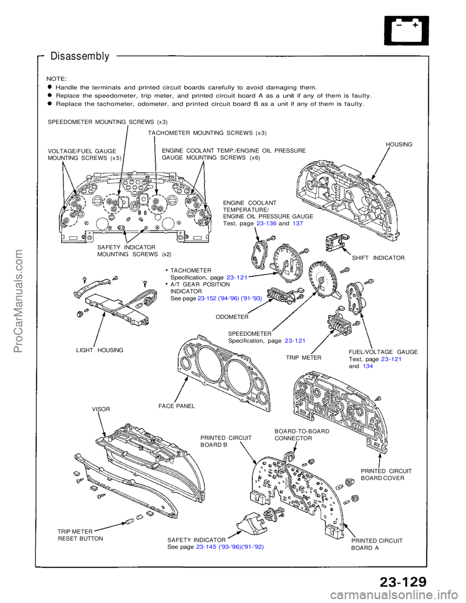
SPEEDOMETER MOUNTING SCREWS (x3) TACHOMETER MOUNTING SCREWS (x3)
VOLTAGE/FUEL GAUGE
MOUNTING SCREWS (x5) ENGINE COOLANT TEMP./ENGINE OIL PRESSURE
GAUGE MOUNTING SCREWS (x6)
HOUSING
ENGINE COOLANT
TEMPERATURE/
ENGINE OIL PRESSURE GAUGE
Test, page 23-136 and 137
SAFETY INDICATOR
MOUNTING SCREWS (x2) SHIFT INDICATOR
TACHOMETER
Specification, page 23-121
A/T GEAR POSITION
INDICATOR
See page 23-152 ('94-'96) ('91-'93)
LIGHT HOUSING
ODOMETER
SPEEDOMETER
Specification, page 23-121
TRIP METER FUEL/VOLTAGE GAUGE
Test, page 23-121
and 134
FACE PANEL PRINTED CIRCUIT
BOARD B
BOARD-TO-BOARD
CONNECTOR
PRINTED CIRCUIT
BOARD COVER
PRINTED CIRCUIT
BOARD A
SAFETY INDICATOR
See page 23-145 ('93-'96)('91-'92)
TRIP METER
RESET BUTTON
VISORProCarManuals.com
Page 1036 of 1640
Cylinder Heads
Installation (cont'd)
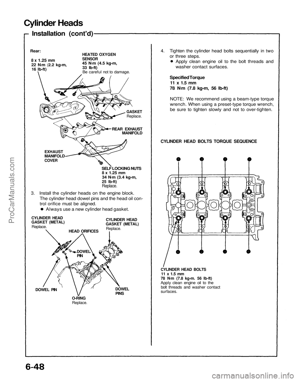
Rear:
8 x
1.25
mm
22 N .
m
(2.2 kg-m,
16 Ib-ft)
HEATED OXYGEN
SENSOR
45 N .
m
(4.5 kg-m,
33 Ib-ft) Be careful not to damage.
GASKET
Replace.
REAR EXHAUST
MANIFOLD
EXHAUST
MANIFOLD
COVER
SELF LOCKING NUTS
8 x
1.25
mm
34 N .
m
(3.4 kg-m,
25 Ib-ft)
Replace.
3. Install the cylinder heads on the engine block. The cylinder head dowel pins and the head oil con-
trol orifice must be aligned.
CYLINDER HEAD
GASKET (METAL)
Replace.
CYLINDER HEAD
GASKET (METAL)
Replace.
HEAD ORIFICES
DOWEL
PIN
DOWEL PIN
O-RING
Replace.
DOWEL
PINS
CYLINDER HEAD BOLTS
11 x 1.5 mm
78 N .
m (7.8 kg-m. 56 Ib-ft)
Apply clean engine oil to the bolt threads and washer contact
surfaces.
CYLINDER HEAD BOLTS TORQUE SEQUENCE
Specified Torque
11 x 1.5 mm
78 N .
m (7.8 kg-m, 56 Ib-ft)
NOTE: We recommend using a beam-type torque
wrench. When using a preset-type torque wrench,
be sure to tighten slowly and not to over-tighten.
Always use a new cylinder head gasket. Apply clean engine oil to the bolt threads and
washer contact surfaces.
4. Tighten the cylinder head bolts sequentially in two
or three steps.ProCarManuals.com