Page 165 of 1640

Engine Coolant Refilling and Bleeding
CAUTION: When pouring engine coolant, be sure to
shut the relay box lid and not let coolant spill on the
electrical parts or the paint. If any coolant spills, rinse it
off immediately.
NOTE:
• Perform this maintenance when the engine is cool.
• Before replacing the coolant, turn the ignition ON,
slowly turn the climate control temperature knob to
90° and turn off the ignition. This will allow the
coolant in the heater to drain out with the rest of the
system.
1. Open the hood, the rear window and the engine
cover.
2. Remove the cover protecting the water pipes and
shift cables on the underside of the car.
3. Before removing the expansion tank cap, first
loosen the cap to lower pressure.
CAUTION: Do not remove the expansion tank cap
when engine is hot. The coolant is under pressure
and may blow out and scald you. Open the cap
slowly when the engine is cool.
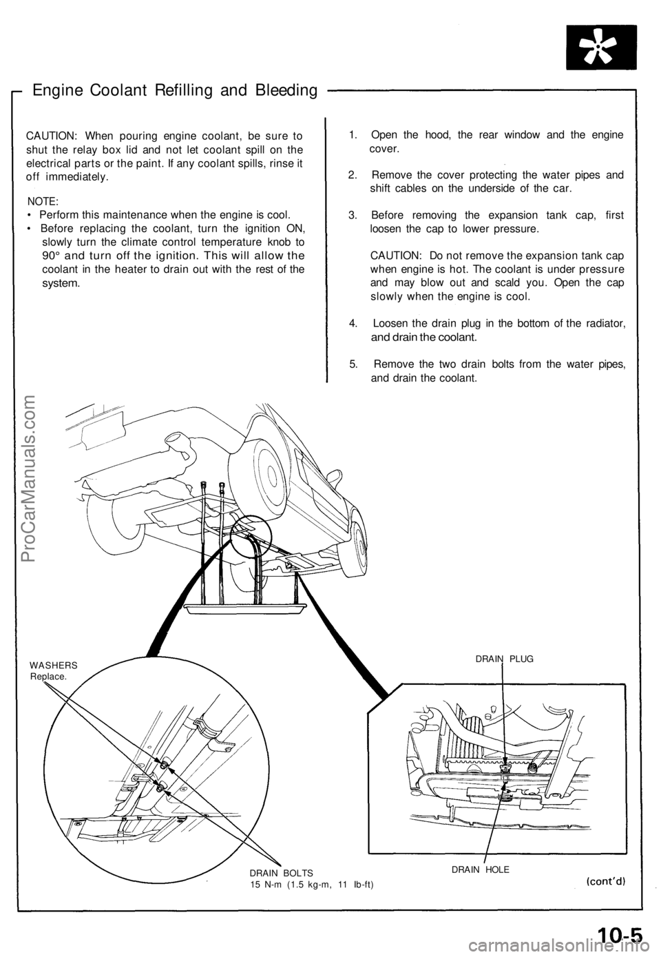
4. Loosen the drain plug in the bottom of the radiator,
and drain the coolant.
5. Remove the two drain bolts from the water pipes,
and drain the coolant.
WASHERS
Replace.
DRAIN BOLTS
15 N-m (1.5 kg-m, 11 Ib-ft)
DRAIN HOLE
DRAIN PLUGProCarManuals.com
Page 485 of 1640

Rear Damper
Removal
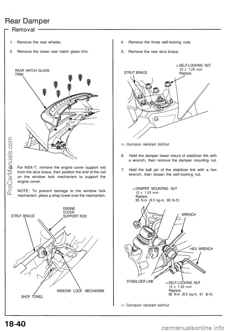
1. Remove the rear wheels.
2. Remove the lower rear hatch glass trim.
REAR HATCH GLASS
TRIM
3. For NSX-T, remove the engine cover support rod
from the strut brace, then position the end of the rod
on the window lock mechanism to support the
engine cover.
NOTE: To prevent damage to the window lock
mechanism, place a shop towel over the mechanism.
STRUT BRACE
ENGINE
COVER
SUPPORT ROD
WINDOW LOCK MECHANISM
SHOP TOWEL
4. Remove the three self-locking nuts.
5. Remove the rear strut brace.
STRUT BRACE
SELF-LOCKING NUT
10 x
1.25
mm
Replace.
Corrosion resistant bolt/nut
6. Hold the damper lower mount of stabilizer link with
a wrench, then remove the damper mounting nut.
7. Hold the ball pin of the stabilizer link with a hex
wrench, then loosen the self-locking nut.
DAMPER MOUNTING NUT
12 x
1.25
mm
Replace.
95 N-m (9.5 kg-m, 69 Ib-ft)
WRENCH
HEX WRENCH
STABILIZER LINK
SELF-LOCKING NUT
12 x
1.25
mm
Replace.
85 N-m (8.5 kg-m, 61 Ib-ft)
Corrosion resistant bolt/nutProCarManuals.com
Page 491 of 1640
Special Tools
Ref.
No.
Tool Number
07HAA – SG00100 or
07HAA – SG00101
07HAE – SG00100
07HAJ – SG00100or
07HAJ – SG0010B
07JAG – SD40100
07KA2 – 001000A
07914 – SA50000
Description
Bleeder T-Wrench
Brake Spring Compressor
ALB Checker (US)
Pushrod Adjustment Gauge
Auxiliary Window Switch
Snap Ring Pliers
Qty
1
1
1
1
1
1
Page Reference
19-62('91-'92)('93-'96),64('91-'92)('93-'96),65('91-'92)
('93-'96),69('91-'92)('93-'96)
19-21, 24
19-41, 43, 64('91-'92)('93-'96),
69('91-'92)('93-'96)
19-15
19-65('91-'92)('93-'96)
19-21,
24
ProCarManuals.com
Page 564 of 1640
Doors
REAR SASH
Adjustment, see page 20-17('93-'96),16('91-'92)
REAR GLASS
GUIDE
Index
FRONT GLASS
GUIDE
REGULATOR
ASSEMBLY
INNER MOLDING STOPPER
PLATES GLASS
Adjustment, see page 20-14('93-'96),
13('91-'92)
FRONT SASH
Adjustment, see page 20-17('93-'96),
16('91-'92)
POWER MIRROR
INSIDE STABILIZERS OUTER MOLDING
DOOR HINGE
POWER WINDOW
MOTOR
LOCK
CYLINDER
DOOR
Disassembly, see page 20-7
('93-'96),6('91-'92)
Assembly, see page 20-13
('93-'96),12('91-'92)
Adjustment, see page 20-19
('93-'96),18('91-'92)
STRIKER
Adjustment, see page 20-19
('93-'96),18('91-'92)
LOCK ROD
LATCH
ASSEMBLY INNER HANDLE HANDLE CABLE
TRIM PLATE POWER DOOR
LOCK SWITCHDOOR
PANEL
LOCK
CRANK
PLASTIC
COVER
DETENT
ROD
LOWER
WEATHERSTRIP
INNER
WEATHERSTRIP
AIR DUCT
Passenger's:
SWITCH PANEL
ARMREST
COURTESY
LIGHT
SWITCH PANEL
POWER WINDOW
SWITCHProCarManuals.com
Page 566 of 1640
Doors
Disassembl y
5. Remov e th e mountin g screws . Lif t th e doo r pane l
straigh t u p of f th e sill .
Disconnec t th e connectors :
• Trun k li d opene r
• Powe r window/Doo r mirro r
• Courtes y ligh t
• Securit y alar m
CONNECTOR S
DOO R PANE L
MOUNTIN G SCRE W
6. Remov e th e switc h pane l an d ai r duc t fro m th e
doo r pane l a s required .
SWITCH PANE L
AI R DUC T
DOOR PANE L
7. Remov e th e mountin g screw s an d disconnec t th e
connectors , the n remov e th e powe r windo w con -
trol uni t an d speake r unit .
POWE R WINDO W
CONTRO L UNI T
CONNECTORS
MOUNTINGSCREW
SPEAKE R UNI T
CONNECTO R
8. Remov e th e lowe r doo r weatherstri p retainin g
clips, the n pul l of f th e lowe r doo r weatherstrip .
Remov e th e scre w grommets , an d carefull y remov e
th e plasti c cover .
Clip location s Cli
p location s
LOWERWEATHERSTRI PPLASTI
C COVE R
SCRE
W GROMMET S
ProCarManuals.com
Page 580 of 1640
Windshield, Rear Window, Rear Hatch Glass
Index
( ): Quantity of parts used.
REAR HATCH GLASS
Removal. see page 20-33
('93-'96),32('91-'92)
Installation, see page 20-33
('93-'96),32('91-'92)
UPPER RUBBER
DAM
MOLDING
Replacement, see page 20-36('93-'96),
35('91-'92)
INNER RUBBER
DAM
OUTER RUBBER
DAM
UPPER MOLDING LOWER MOLDING
LOWER RUBBER
DAM
WINDSHIELD
Removal, see page 20-23
('93-'96),22('91-'92)
Installation, see page 20-24
('93-'96),23('91-'92)
REAR WINDOW
Removal, see page 20-27('93-'96),26('91-'92)
Instatiation, see page 20-29('93-'96),28
('91-'92)
UPPER MOLDING
UPPER FASTENER
RUBBER DAM
LOWER SPACER (2)ProCarManuals.com
Page 586 of 1640

Rear Window
Removal
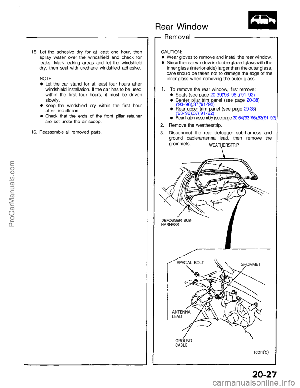
CAUTION: Wear gloves to remove and install the rear window.
Since the rear window is double glazed glass with the
Inner glass (interior-side) larger than the outer glass,
care should be taken not to damege the edge of the
inner glass when removing the outer glass.
To remove the rear window, first remove: Seats (see page 20-39('93-'96),('91-'92)
Center pillar trim panel (see page 20-38)('93-'96),37('91-'92)
Rear upper trim panel (see page 20-38)
('93-'96),37('91-'92)
Rear hatch assembly (see page 20-64('93-'96),53('91-'92)
2. Remove the weatherstrip.
3. Disconnect the rear defogger sub-harness and
ground cable/antenna lead, then remove the
grommets.
WEATHERSTRIP
DEFOGGER SUB-
HARNESS
GROMMET
(cont'd)
GROUND
CABLE
ANTENNA
LEAD
SPECIAL BOLT
15. Let the adhesive dry for at least one hour, then
spray water over the windshield and check for
leaks. Mark leaking areas and let the windshield
dry, then seal with urethane windshield adhesive.
NOTE:
Let the car stand for at least four hours after
windshield installation. If the car has to be used
within the first four hours, it must be driven
slowly.
Keep the windshield dry within the first hour
after installation.
Check that the ends of the front pillar retainer
are set under the air scoop.
16. Reassemble all removed parts.
1.ProCarManuals.com
Page 587 of 1640

Rear Windo w
Remova l
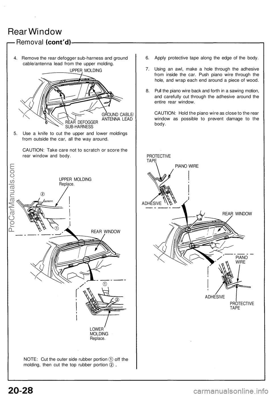
4. Remov e th e rea r defogge r sub-harnes s an d groun d
cable/antenn a lea d fro m th e uppe r molding .
UPPER MOLDIN G
REAR DEFOGGE RSUB-HARNES S
GROUND CABLE /ANTENN A LEA D
5. Us e a knif e t o cu t th e uppe r an d lowe r molding s
fro m outsid e th e car , al l th e wa y around .
CAUTION : Tak e car e no t t o scratc h o r scor e th e
rea r windo w an d body .
UPPER MOLDIN GReplace.
REAR WINDO W
LOWERMOLDIN GReplace.
NOTE: Cu t th e oute r sid e rubber portion
molding , the n cu t th e to p rubbe r portio n 6
. Appl y protectiv e tap e alon g th e edg e of the body .
7 . Usin g a n awl , mak e a hol e throug h th e adhesiv e
fro m insid e th e car . Pus h pian o wir e throug h th e
hole , an d wra p eac h en d aroun d a piec e of wood .
8 . Pul l th e pian o wir e bac k an d fort h in a sawin g motion ,
an d carefull y cu t throug h th e adhesiv e aroun d th e
entir e rea r window .
CAUTION : Hol d th e pian o wir e a s clos e to th e rea r
windo w a s possibl e t o preven t damag e t o th e
body .
PROTECTIV ETAPE
PIAN O WIR E
ADHESIV E
REAR WINDO W
ADHESIV E
PROTECTIV ETAPE
PIAN OWIRE
off th e
ProCarManuals.com