Page 920 of 1640
Troubleshooting
Rear Window Defogger
NOTE: The numbers in the table show the troubleshooting sequence.ProCarManuals.com
Page 922 of 1640
Rear Window Defogger
Switch Replacement (cont'd)
5. Disconnect the 18-P and 10-P connectors.
CAUTION: Be careful not to damage the SRS wire
harness.
6. Remove the six screws, then remove the rear win-
dow defogger-light switch assembly.
10-P CONNECTOR
18-P CONNECTOR
REAR WINDOW DEFOGGER-
LIGHT SWITCH ASSEMBLY
7. If necessary, replace the rear window defogger
switch bulbs.
REAR WINDOW
DEFOGGER SWITCH
BULBS (0.91 W)ProCarManuals.com
Page 925 of 1640

Rear Window Defogger
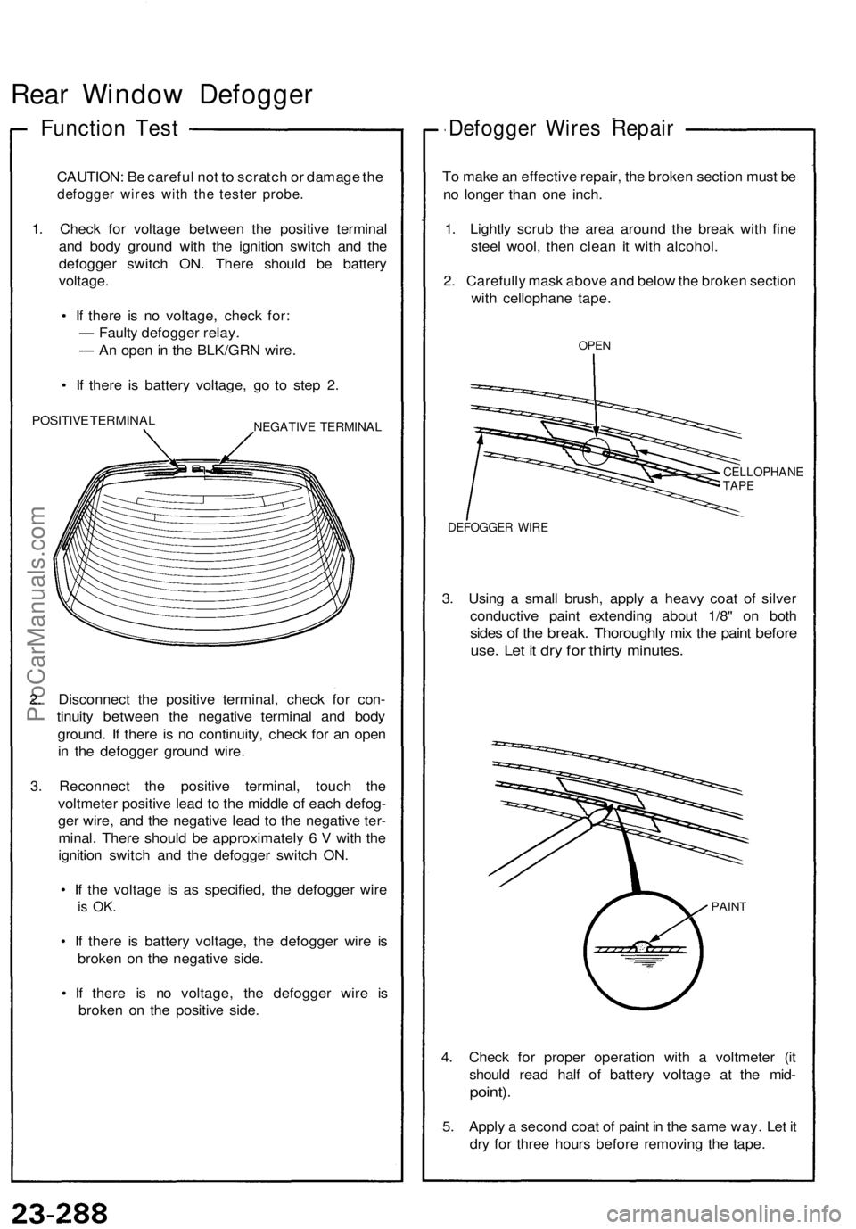
Function Test
CAUTION: Be careful not to scratch or damage the
defogger wires with the tester probe.
1. Check for voltage between the positive terminal
and body ground with the ignition switch and the
defogger switch ON. There should be battery
voltage.
• If there is no voltage, check for:
— Faulty defogger relay.
— An open in the BLK/GRN wire.
• If there is battery voltage, go to step 2.
POSITIVE TERMINAL
NEGATIVE TERMINAL
2. Disconnect the positive terminal, check for con-
tinuity between the negative terminal and body
ground. If there is no continuity, check for an open
in the defogger ground wire.
3. Reconnect the positive terminal, touch the
voltmeter positive lead to the middle of each defog-
ger wire, and the negative lead to the negative ter-
minal. There should be approximately 6 V with the
ignition switch and the defogger switch ON.
• If the voltage is as specified, the defogger wire
is OK.
• If there is battery voltage, the defogger wire is
broken on the negative side.
• If there is no voltage, the defogger wire is
broken on the positive side.
Defogger Wires Repair
To make an effective repair, the broken section must be
no longer than one inch.
1. Lightly scrub the area around the break with fine
steel wool, then clean it with alcohol.
2. Carefully mask above and below the broken section
with cellophane tape.
OPEN
CELLOPHANE
TAPE
DEFOGGER WIRE
3. Using a small brush, apply a heavy coat of silver
conductive paint extending about 1/8" on both
sides of the break. Thoroughly mix the paint before
use. Let it dry for thirty minutes.
PAINT
4. Check for proper operation with a voltmeter (it
should read half of battery voltage at the mid-
point).
5. Apply a second coat of paint in the same way. Let it
dry for three hours before removing the tape.ProCarManuals.com
Page 1350 of 1640
EPS Control unit
Replacement
CAUTION: Be careful not to damage the SRS wire
harnesses when servicing the control unit. 1. Remove the dashboard lower cover and glove box
and disconnect the light connector.
3. Disconnect the connectors from the EPS control
unit by removing the wire harness band.
EPS CONTROL UNIT
4. Remove the power window control unit by pulling it
toward you, then remove the EPS control unit.
5. Installation is the reverse of the removal procedure.
NOTE: Turn the ignition switch ON and check the
EPS indicator light for operation.
HEATER DUCT
2. Move the heater duct right then remove the heater
duct.
DASHBOARD LOWER COVER
GLOVE BOX
EPS CONTROL UNIT
POWER WINDOW CONTROL
UNIT
10 N ·
m
(1.0 kg-m, 7 Ib-ft)
All SRS wire harnesses and connectors
are colored yellow. Do not use electrical test equipment
on these circuits.
CONNECTORSProCarManuals.com
Page 1385 of 1640
Dashboard, Door and Floor
DRIVER'S DOOR PANEL
POWER WINDOW
CONTROL UNIT
CIGARETTE LIGHTER
RELAY
SRS UNIT
FOOT WELL BASS SPEAKER RIGHT FRONT FLOOR
PANEL
EPS POWER UNIT
(Behind foot well
bass speaker)
SECURITY CONTROL UNIT
DAYTIME RUNNING
LIGHTS CONTROL
UNIT (Canada)
ABS CONTROL UNIT
CRUISE CONTROL UNIT
EPS CONTROL UNIT
(A/T)
POWER DOOR LOCK
CONTROL UNIT
Wire colors: YEL/RED, BLU/GRN, BRN/YEL, and BLKProCarManuals.com
Page 1388 of 1640
Relay and Control Unit Locations
Engine Compartment
REAR WINDOW DEFOGGER
RELAY
ENGINE COMPARTMENT
FUSE/RELAY BOX
ENGINE COMPARTMENT
FAN RELAY
Wire colors: YEL/BLU,
BLK/YEL, WHT/RED,
and WHT/BLU
IGNITION CONTROL
MODULE (ICM)ProCarManuals.com
Page 1427 of 1640
Troubleshooting
NOTE: The numbers in the table show the troubleshooting sequence.
Item to be inspected
Symptom
Both windows do not
operate.
Driver's window does not
operate in any position.
Driver's window does not
operate in AUTO.
Passenger's window does
not operate.
Both windows do not
operate within the first
ten minutes after the igni-
tion switch has been turn-
ed
OFF.ProCarManuals.com
Page 1428 of 1640

Rear Window Defogger
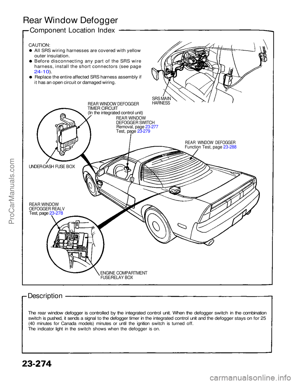
Component Location Index
CAUTION:
Al
l
SRS wiring harnesses are covered with yellow
outer insulation.
Befor
e
disconnecting any part of the SRS wire
harness
,
install the short connectors (see page
24-10).
Replac
e
the entire affected SRS harness assembly if
it
has an open circuit or damaged wiring.
REA
R
WINDOW DEFOGGERTIME
R
CIRCUIT(I
n
the integrated control unit)
SRS MAIN
HARNESS
REA
R
WINDOWDEFOGGE
R
SWITCHRemoval
,
page 23-277
Test, page 23-279
REAR WINDOW DEFOGGER
Functio
n
Test, page 23-288
UNDER-DASH FUSE BOX
REA
R
WINDOWOEFOGGE
R
REALV
Test, page 23-278
ENGIN
E
COMPARTMENT
FUSE/RELAY BOX
Description
The rear window defogger is controlled by the integrated control unit. When the defogger switch in the combination
switch is pushed, it sends a signal to the defogger timer in the integrated control unit and the defogger stays on for 25
(40 minutes for Canada models) minutes or until the ignition switch is turned off.
The indicator light in the switch shows when the defogger is on.ProCarManuals.com