Page 72 of 1640

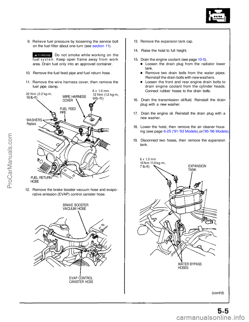
9. Relieve fuel pressure by loosening the service bolt
on the fuel filter about one turn (see section 11).
Do not smoke while working on the
fuel
system.
Keep open flame away from work
area. Drain fuel only into an approved container.
10. Remove the fuel feed pipe and fuel return hose.
11. Remove the wire harness cover, then remove the fuel pipe clamp.
22 N·m
(2.2 kg-m,
16 Ib-ft)
WIRE HARNESS
COVER
6 x 1.0 mm
12 N·m
(1.2 kg-m,
9 lb-ft)
FUEL FEED
PIPE
WASHERS
Replace.
FUEL RETURN
HOSE
12. Remove the brake booster vacuum hose and evapo- rative emission (EVAP) control canister hose.
BRAKE BOOSTER
VACUUM HOSE
EVAP CONTROL
CANISTER HOSE
13. Remove the expansion tank cap.
14. Raise the hoist to full height.
15. Drain the engine coolant (see page
10-5).
Loosen the drain plug from the radiator lower
tank. Remove two drain bolls from the water pipes.
Reinstall the drain bolts with new washers.
Loosen the front and rear engine drain bolts to
drain engine coolant from the cylinder heads.
Connect rubber hoses to the drain bolts.
16. Drain the transmission oil/fluid. Reinstall the drain plug with a new washer.
17. Drain the engine oil. Reinstall the drain plug with a
new washer.
18. Lower the hoist, then remove the air cleaner hous-
ing (see page 6-25 ('91-'93 Mode ls),or('95-'96 Models).
19. Disconnect two hoses, then remove the expansion
tank.
6 x 1.0 mm
10 N·m
11.0 kg-m,
7 lb-ft)
EXPANSION
TANK
WATER BYPASS
HOSES
(cont'd)ProCarManuals.com
Page 100 of 1640

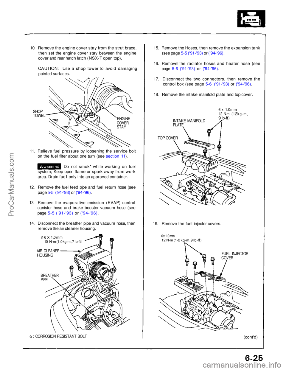
10. Remove the engine cover stay from the strut brace,
then set the engine cover stay between the engine
cover and rear hatch latch (NSX-T open top),
CAUTION: Use a shop tower to avoid damaging
painted surfaces.
SHOP
TOWEL
11. Relieve fuel pressure by loosening the service bolt on the fuel filter about one turn (see section 11).
Do not smok* while working on fuel
system; Keep open flame or spark away from work
area. Drain fue1 only into an approved container.
12. Remove the fuel feed pipe and fuel return hose (see page 5-5 ('91-'93) or ('94-'96).
13. Remove the evaporative emission (EVAP) control
canister hose and brake booster vacuum hose (see
page 5-5 ('91-'93) or ('94-'96).
14. Disconnect the breather pipe and vacuum hose, then remove the air cleaner housing.
6 x 1.0 mm
10 N·m (1.0 kg-m, 7 lb-ftl
AIR CLEANER
HOUSING
BREATHER
PIPE
: CORROSION RESISTANT BOLT
15. Remove the Hoses, then remove the expansion tank
(see page 5-5 ('91-'93) or ('94-'96).
16. Removel the radiator hoses and heater hose (see
page 5-6 ('91-'93) or ('94-'96).
17. Disconnect the two connectors, then remove the
control box (see page 5-6 ('91-'93) or ('94-'96).
18. Remove the intake manifold plate and top cover.
INTAKE MANIFOLD
PLATE
6 x
1.0mm
12 N·m (12kg-m,
9 lb-ft)
TOP COVER
19. Remove the fuel injector covers.
6 x 1.0 mm
12 N·m (1-2 kg-m, 9 lb-ft)
FUEL INJECTOR
COVER
(cont'd)
ENGINE
COVER
STAYProCarManuals.com
Page 228 of 1640

PGM-FI System
System Description
PGM-FI System
The PGM-FI system on this model is a sequential multiport fuel injection system.
Fuel Injector Timing and Duration
The ECM contains memories for the basic discharge durations at various engine speeds and manifold pressures. The
basic discharge duration, after being read out from the memory, is further modified by signals sent from various sensors
to obtain the final discharge duration.
Throttle Valve Control
The ECM controls the throttle valve control motor based on accelerator pedal position, TCS control unit and various sig-
nals. The ECM also controls the idle control function, cruise control function, and other functions with the throttle valve
control.
Ignition Timing Control
• The ECM contains memories for basic ignition timing at various engine speeds and manifold pressures. Ignition timing
is also adjusted for engine coolant temperature.
• A knock control system is also used. When detonation is detected by the knock sensor (KS), the ignition timing is
retarded.
Other Control Functions
1. Starting Control
When the engine is started, the ECM provides a rich mixture by increasing fuel injector duration.
2. Fuel Pump Control
• When the ignition switch is initially turned on, the ECM supplies ground to the PGM-FI main relay that supplies
current to the fuel pump for two seconds to pressurize the fuel system.
• When the engine is running, the ECM supplies ground to the PGM-FI main relay that supplies current to the fuel pump.
• When the engine is not running and the ignition is on, the ECM cuts ground to the PGM-FI main relay which cuts
current to the fuel pump.
• Excellent engine performance is achieved through the use of VTEC (Variable Valve Timing and Valve Lift Electronic
Control System), intake air bypass control and discharge volume control of the fuel pump.ProCarManuals.com
Page 252 of 1640

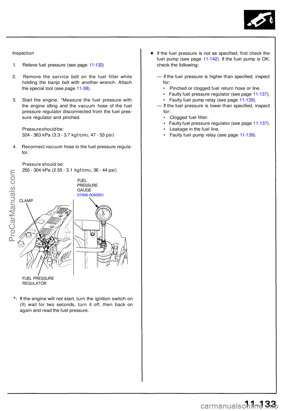
Inspection
1 . Reliev e fue l pressur e (se e pag e 11-132 )
2 . Remov e th e servic e bol t o n th e fue l filte r whil e
holdin g th e banj o bol t wit h anothe r wrench . Attac h
th e specia l too l (se e pag e 11-38 ).
3 . Star t th e engine . *Measur e th e fue l pressur e wit h
th e engin e idlin g an d th e vacuu m hos e o f th e fue l
pressur e regulato r disconnecte d fro m th e fue l pres -
sur e regulato r an d pinched .
Pressur e shoul d be :
32 4 - 36 3 kP a (3. 3 - 3. 7 kgf/cm
2, 4 7 - 5 3 psi )
4 . Reconnec t vacuu m hos e to th e fue l pressur e regula -
tor.
Pressur e shoul d be :
250 - 30 4 kP a (2.5 5 - 3. 1 kgf/cm2, 3 6 - 4 4 psi )
FUE LPRESSUR EGAUGE07406-004000 1
CLAMP
FUEL PRESSUR EREGULATO R
If th e engin e wil l no t start , tur n th e ignitio n switc h o n
(II ) wai t fo r tw o seconds , tur n i t off , the n bac k o n
agai n an d rea d th e fue l pressure . I
f th e fue l pressur e i s no t a s specified , firs t chec k th e
fue l pum p (se e pag e 11-142 ). I f th e fue l pum p i s OK ,
chec k th e following :
— If th e fue l pressur e is highe r tha n specified , inspec t
for:
• Pinche d o r clogge d fue l retur n hos e o r line .
• Fault y fue l pressur e regulato r (se e pag e 11-137 ).
• Fault y fue l pum p rela y (se e pag e 11-139 ).
— If th e fue l pressur e is lowe r tha n specified , inspec t
for:
• Clogge d fue l filter .
• Fault y fue l pressur e regulato r (se e pag e 11-137 ).
• Leakage in th e fue l line .
• Fault y fue l pum p rela y (se e pag e 11-139 ).
ProCarManuals.com
Page 254 of 1640
13. Install the fuel injectors and fuel rail assembly in the manifold.
CAUTION: To prevent damage to the O-rings, install the fuel injectors in the fuel rail first, then install them in the
intake manifold.
FUEL
RAILS
FUEL RAIL
INSULATOR
FUEL RAIL
14. Align the center line on the connector with the mark on the fuel rail.
15. Install and tighten the retainer nuts.
16. Connect the fuel hose to the fuel rail.
17. Connect the vacuum hose and fuel return hose to the fuel pressure regulator.
18. Install the connectors on the fuel injectors and the IAT sensor.
19. Install the intake manifold covers.
20. Turn the ignition switch ON (II), but do not operate the starter. After the fuel pump runs for approximately two seconds,
the fuel pressure in the fuel line rises. Repeat this two or three times, then check whether there is any fuel leakage.
MARKINGSProCarManuals.com
Page 280 of 1640

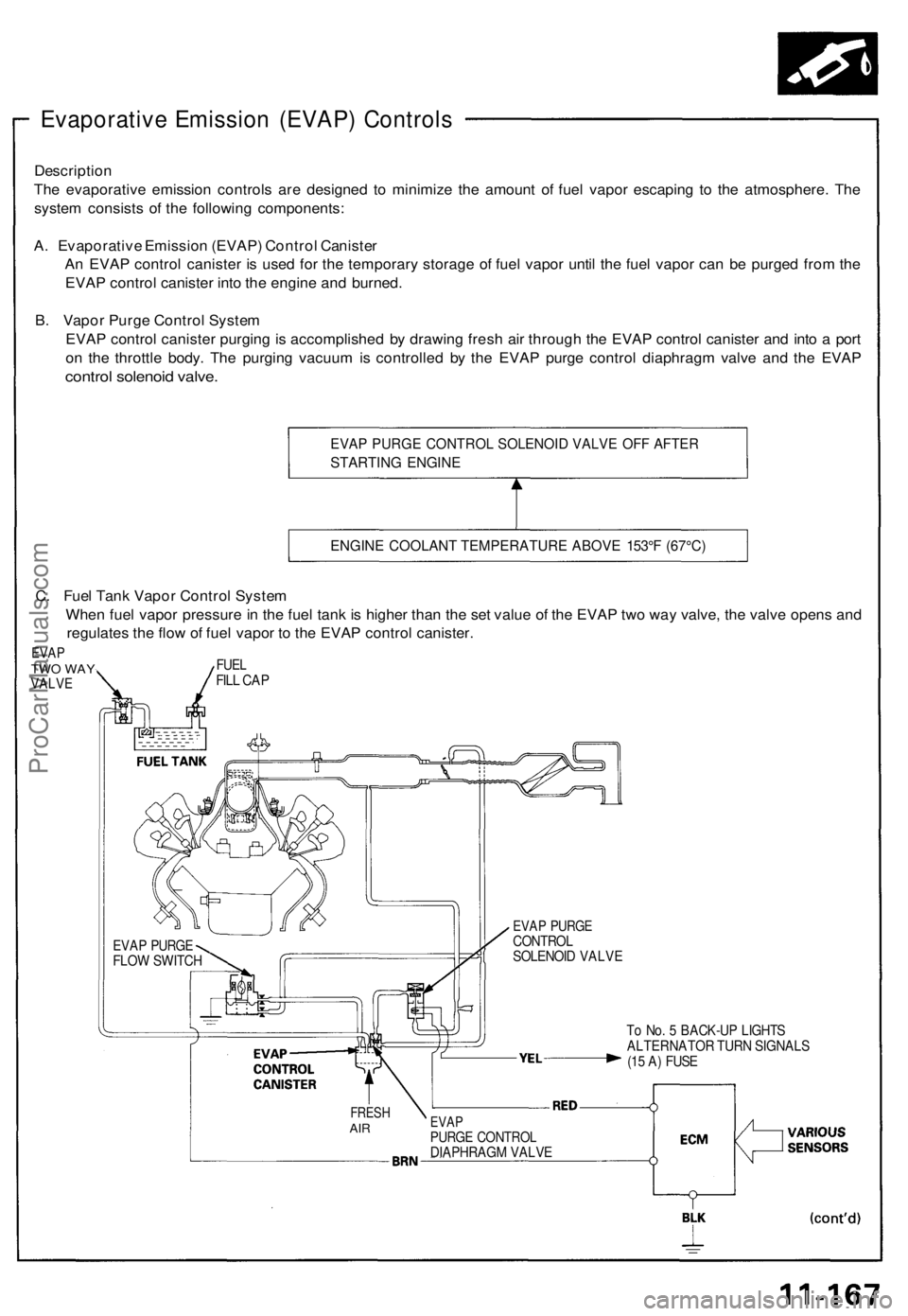
Evaporative Emission (EVAP) Controls
Description
The evaporative emission controls are designed to minimize the amount of fuel vapor escaping to the atmosphere. The
system consists of the following components:
A. Evaporative Emission (EVAP) Control Canister
An EVAP control canister is used for the temporary storage of fuel vapor until the fuel vapor can be purged from the
EVAP control canister into the engine and burned.
B. Vapor Purge Control System
EVAP control canister purging is accomplished by drawing fresh air through the EVAP control canister and into a port
on the throttle body. The purging vacuum is controlled by the EVAP purge control diaphragm valve and the EVAP
control solenoid valve.
EVAP PURGE CONTROL SOLENOID VALVE OFF AFTER
STARTING ENGINE
ENGINE COOLANT TEMPERATURE ABOVE 153°F (67°C)
To No. 5 BACK-UP LIGHTS
ALTERNATOR TURN SIGNALS
(15 A) FUSE
FRESH
AIR
EVAP
PURGE CONTROL
DIAPHRAGM VALVE
EVAP PURGE
CONTROL
SOLENOID VALVE
EVAP PURGE
FLOW SWITCH
C. Fuel Tank Vapor Control System
When fuel vapor pressure in the fuel tank is higher than the set value of the EVAP two way valve, the valve opens and
regulates the flow of fuel vapor to the EVAP control canister.
EVAP
TWO WAY
VALVE
FUEL
FILL CAPProCarManuals.com
Page 786 of 1640
Gauge Assembly
Gauge/Terminal Location Index
SRS components are located in this area. Review the SRS component locations, precautions, and procedures in the SRS
section (24) before performing repairs or service.
SPEEDOMETER:
Indicates 60 mph [60km/h] at 1.026 [637]
rpm of the vehicle speed sensor (VSS).
FUEL GAUGE: Gauge test, page 23-134 Sending Unit Test, page 23-135
VOLTAGE METER:
If, with the No. 5 (15 A) fuse
and other gauges
OK, the pointer of the
voltage meter does not move at all,
replace the voltage
meter.
SAFETY INDICATOR SYSTEM:
See page 23-145 ('93-'96) ('91-'92)A/T GEAR POSITION
INDICATOR SYSTEM:
See page 23-156 ENGINE OIL PRESSURE
GAUGE:
Test page 23-137
ENGINE COOLANT TEMPERATURE (ECT) GAUGE:
Gauge Test, page 23-136 Sender Test, page 23-136
TACHOMETER:
Indicates 100 rpm at 300 pulses per minute
of the igniter unit.ProCarManuals.com
Page 789 of 1640
Gauge Assembly
Bulb Locations
GAUGE LIGHTS (1.4W x 2)
SRS INDICATOR LIGHT (1.4 W)
RIGHT TURN SIGNAL INDICATOR LIGHT (1.4 W)
EPS INDICATOR LIGHT (1.4 W)
BRAKE SYSTEM LIGHT (1.4 W)
SEAT BELT REMINDER LIGHT (1.4 W)
TCS INDICATOR
LIGHT (1.96 W)
LOW FUEL INDICATOR
LIGHT (1.4 W)
GAUGE LIGHT
(1.4
W)
HIGH BEAM INDICATOR LIGHT (1.4 W)
LEFT TURN SIGNAL INDICATOR LIGHT (1.4 W)
ABS
INDICATOR LIGHT (1.4 W)
CHARGING SYSTEM LIGHT (1.4 W)
MALFUNCTION
INDICATOR
LAMP (MIL)
(1.4W)
LOW OIL PRESSURE
INDICATOR
LIGHT (1.4 W)
GAUGE LIGHT
(1.4
W)
GAUGE LIGHT
(3.0
W)
GAUGE LIGHT
(3.0
W)
GAUGE LIGHT
(3.0
W)
CRUISE INDICATOR LIGHT
(1.96
W)ProCarManuals.com