1991 ACURA NSX gearbox
[x] Cancel search: gearboxPage 403 of 1640
Component Location s
Index
NOTE :
• I f a n intac t airba g assembl y ha s bee n remove d fro m a scrappe d ca r o r ha s bee n foun d defectiv e o r damage d durin g transit ,
storag e o r service , i t shoul d b e deploye d (se e sectio n 24 ).
• Befor e removin g th e gearbox , remov e th e ignitio n ke y t o loc k th e steerin g shaft .
• Afte r installin g th e gearbox , chec k th e whee l alignmen t an d adjus t i f necessary .
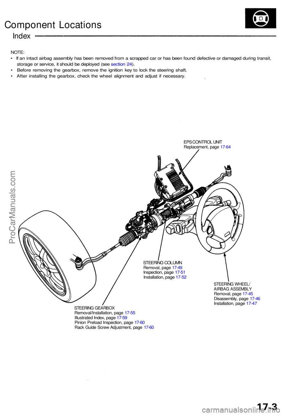
EPS CONTRO L UNI TReplacement , pag e 17-6 4
STEERIN G GEARBO XRemoval/Installation , pag e 17-5 5Illustrate d Index , pag e 17-5 9Pinio n Preloa d Inspection , pag e 17-6 0Rack Guid e Scre w Adjustment , pag e 17-6 0
STEERIN G WHEEL /AIRBAG ASSEMBL YRemoval, pag e 17-4 5Disassembly , pag e 17-4 6Installation , pag e 17-4 7
STEERIN G COLUM NRemoval , pag e 17-4 9Inspection , pag e 17-5 1Installation , pag e 17-5 2
ProCarManuals.com
Page 407 of 1640
Electrical Power Steering (EPS)
Outline
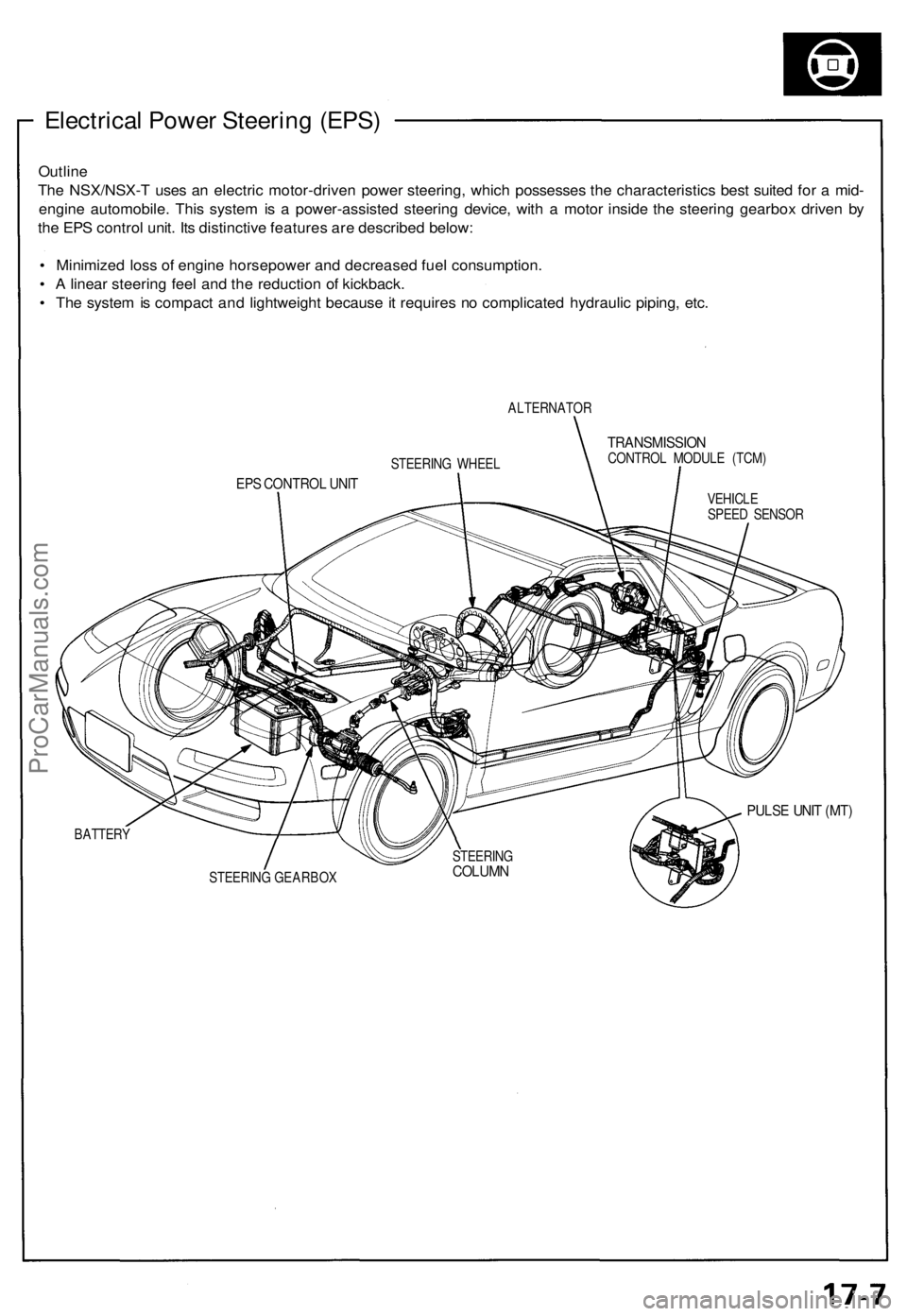
The NSX/NSX-T uses an electric motor-driven power steering, which possesses the characteristics best suited for a mid-
engine automobile. This system is a power-assisted steering device, with a motor inside the steering gearbox driven by
the EPS control unit. Its distinctive features are described below:
• Minimized loss of engine horsepower and decreased fuel consumption.
• A linear steering feel and the reduction of kickback.
• The system is compact and lightweight because it requires no complicated hydraulic piping, etc.
ALTERNATOR
TRANSMISSION
CONTROL MODULE (TCM)
EPS CONTROL UNIT
VEHICLE
SPEED SENSOR
PULSE UNIT (MT)
BATTERY
STEERING GEARBOX
STEERING WHEEL
STEERING
COLUMNProCarManuals.com
Page 408 of 1640
System Description
Major Components
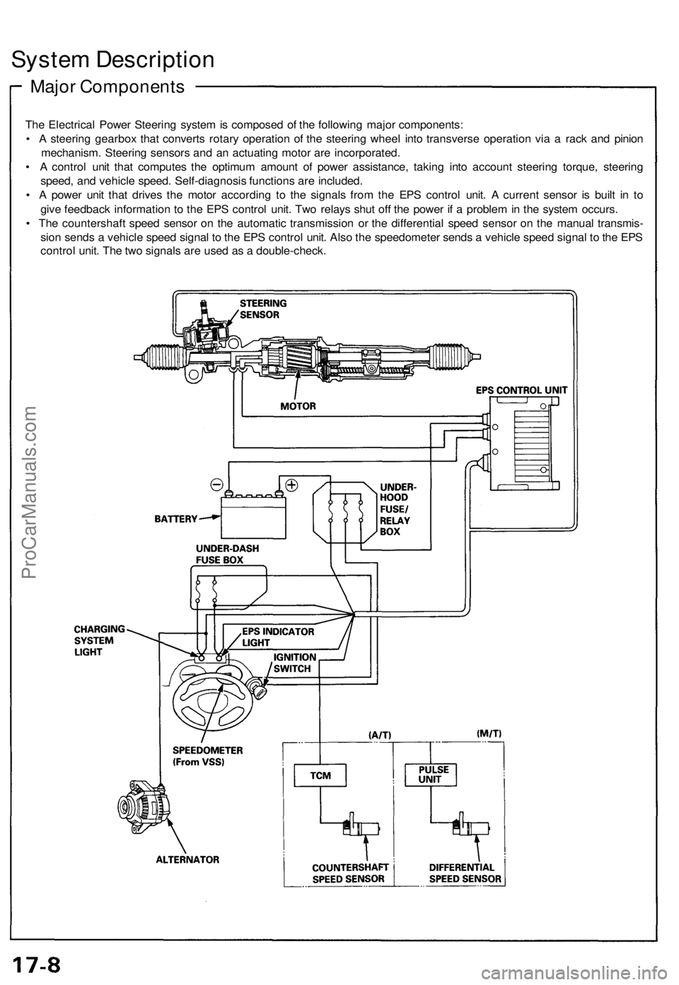
The Electrical Power Steering system is composed of the following major components:
• A steering gearbox that converts rotary operation of the steering wheel into transverse operation via a rack and pinion
mechanism. Steering sensors and an actuating motor are incorporated.
• A control unit that computes the optimum amount of power assistance, taking into account steering torque, steering
speed, and vehicle speed. Self-diagnosis functions are included.
• A power unit that drives the motor according to the signals from the EPS control unit. A current sensor is built in to
give feedback information to the EPS control unit. Two relays shut off the power if a problem in the system occurs.
• The countershaft speed sensor on the automatic transmission or the differential speed sensor on the manual transmis-
sion sends a vehicle speed signal to the EPS control unit. Also the speedometer sends a vehicle speed signal to the EPS
control unit. The two signals are used as a double-check.ProCarManuals.com
Page 409 of 1640
System Operation
Manual Steering Operation
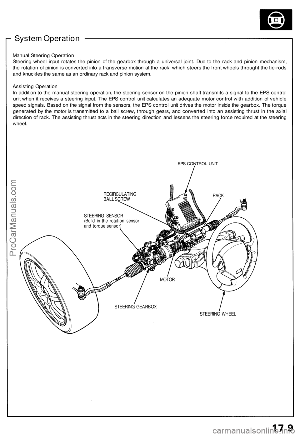
Steering wheel input rotates the pinion of the gearbox through a universal joint. Due to the rack and pinion mechanism,
the rotation of pinion is converted into a transverse motion at the rack, which steers the front wheels throught the tie-rods
and knuckles the same as an ordinary rack and pinion system.
Assisting Operation
In addition to the manual steering operation, the steering sensor on the pinion shaft transmits a signal to the EPS control
unit when it receives a steering input. The EPS control unit calculates an adequate motor control with addition of vehicle
speed signals. Based on the signal from the sensors, the EPS control unit drives the motor inside the gearbox. The torque
generated by the motor is transmitted to a ball screw, through gears, and converted into an assisting thrust in the axial
direction of rack. The assisting thrust acts in the steering direction and lessens the steering force required at the steering
wheel.
EPS CONTROL UNIT
RECIRCULATING
BALL SCREW
STEERING WHEEL
RACK
STEERING SENSOR
(Build in the rotation sensor
and torque sensor)
MOTOR
STEERING GEARBOXProCarManuals.com
Page 411 of 1640
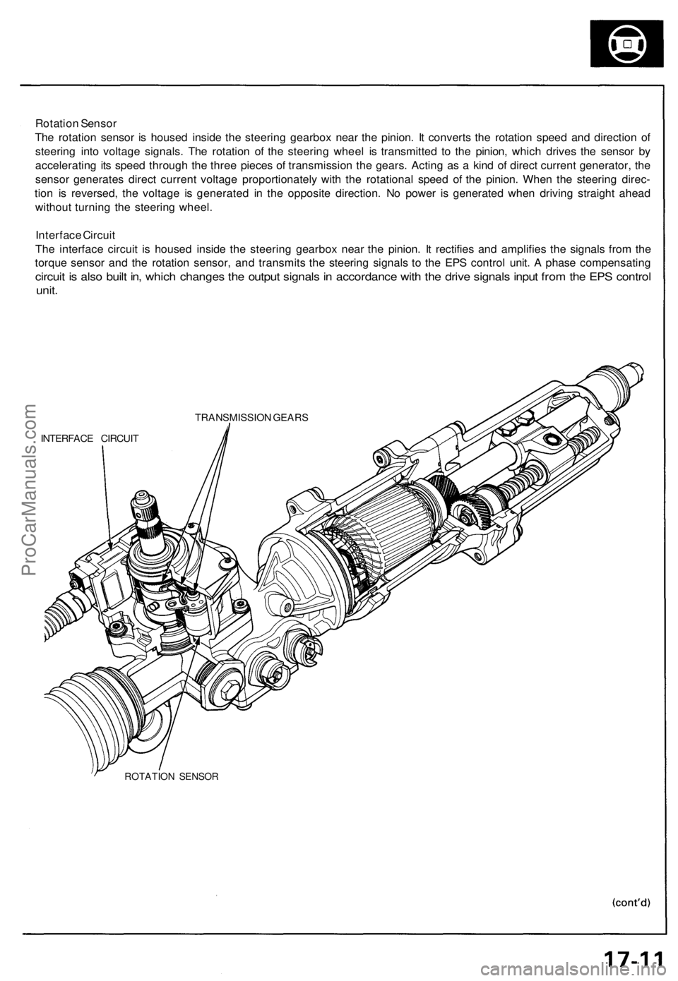
Rotation Sensor
The rotation sensor is housed inside the steering gearbox near the pinion. It converts the rotation speed and direction of
steering into voltage signals. The rotation of the steering wheel is transmitted to the pinion, which drives the sensor by
accelerating its speed through the three pieces of transmission the gears. Acting as a kind of direct current generator, the
sensor generates direct current voltage proportionately with the rotational speed of the pinion. When the steering direc-
tion is reversed, the voltage is generated in the opposite direction. No power is generated when driving straight ahead
without turning the steering wheel.
Interface Circuit
The interface circuit is housed inside the steering gearbox near the pinion. It rectifies and amplifies the signals from the
torque sensor and the rotation sensor, and transmits the steering signals to the EPS control unit. A phase compensating
circuit is also built in, which changes the output signals in accordance with the drive signals input from the EPS control
unit.
TRANSMISSION GEARS
INTERFACE CIRCUIT
ROTATION SENSORProCarManuals.com
Page 415 of 1640
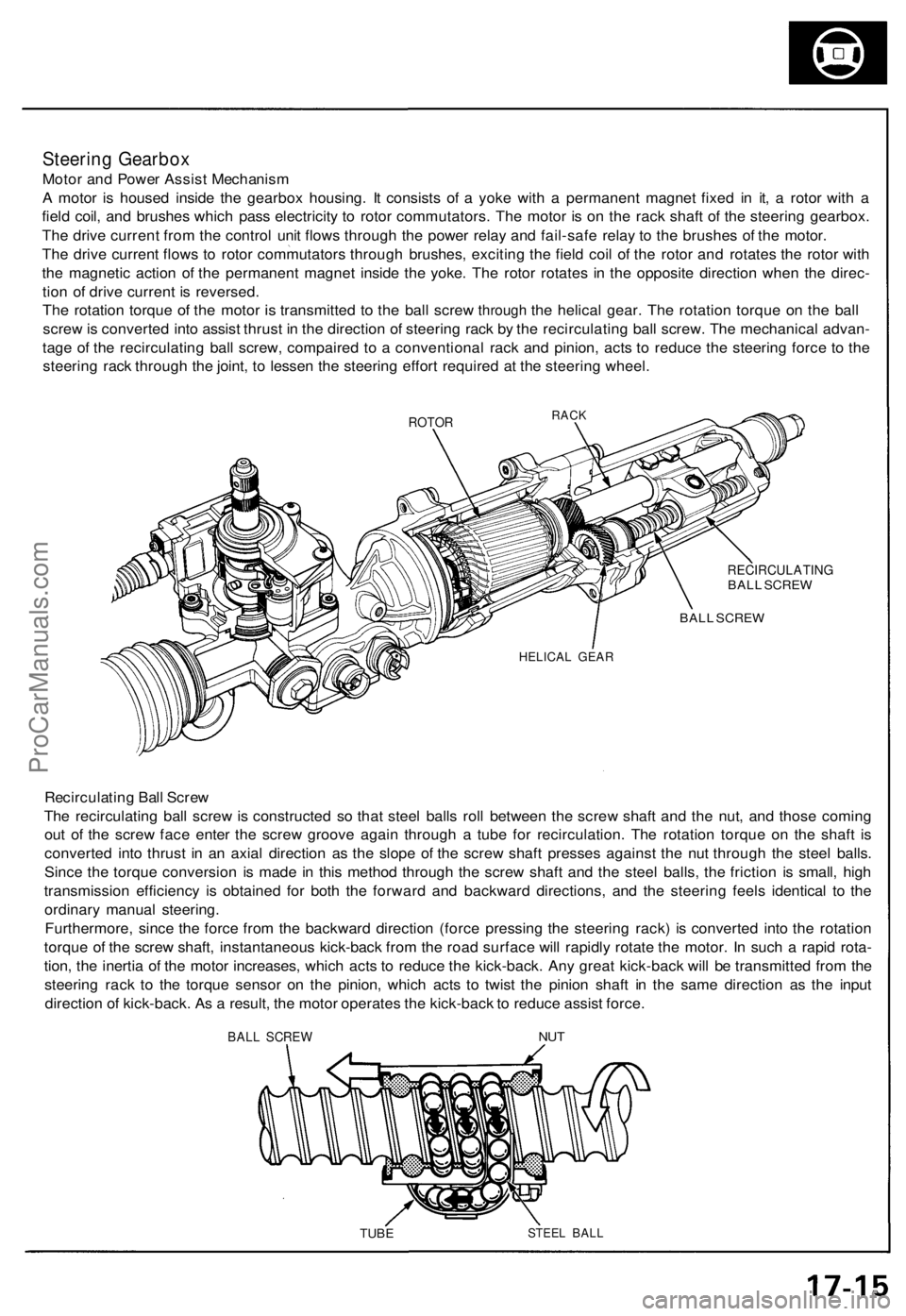
Steering Gearbo x
Motor an d Powe r Assis t Mechanis m
A moto r i s house d insid e th e gearbo x housing . I t consist s o f a yok e wit h a permanen t magne t fixe d i n it , a roto r wit h a
fiel d coil , an d brushe s whic h pas s electricit y t o roto r commutators . Th e moto r i s o n th e rac k shaf t o f th e steerin g gearbox .
Th e driv e curren t fro m th e contro l uni t flow s throug h th e powe r rela y an d fail-saf e rela y t o th e brushe s o f th e motor .
Th e driv e curren t flow s t o roto r commutator s throug h brushes , excitin g th e fiel d coi l o f th e roto r an d rotate s th e roto r wit h
th e magneti c actio n o f th e permanen t magne t insid e th e yoke . Th e roto r rotate s i n th e opposit e directio n whe n th e direc -
tio n o f driv e curren t i s reversed .
The rotatio n torqu e of th e moto r is transmitte d to th e bal l scre w through the helica l gear . The rotatio n torqu e on th e bal l
scre w is converte d int o assis t thrus t i n th e directio n o f steerin g rac k b y th e recirculatin g bal l screw . Th e mechanica l advan -
tag e o f th e recirculatin g bal l screw , compaire d t o a conventiona l rac k an d pinion , act s t o reduc e th e steerin g forc e t o th e
steerin g rac k throug h th e joint , t o lesse n th e steerin g effor t require d a t th e steerin g wheel .
ROTORRACK
RECIRCULATIN GBALL SCRE W
BAL L SCRE W
HELICA L GEA R
Recirculatin g Bal l Scre w
Th e recirculatin g bal l scre w is constructe d s o tha t stee l ball s rol l betwee n th e scre w shaf t an d th e nut , an d thos e comin g
ou t o f th e scre w fac e ente r th e scre w groov e agai n throug h a tub e fo r recirculation . Th e rotatio n torqu e o n th e shaf t i s
converte d int o thrus t i n a n axia l directio n a s th e slop e o f th e scre w shaf t presse s agains t th e nu t throug h th e stee l balls .
Sinc e th e torqu e conversio n i s mad e i n thi s metho d throug h th e scre w shaf t an d th e stee l balls , th e frictio n i s small , hig h
transmissio n efficienc y i s obtaine d fo r bot h th e forwar d an d backwar d directions , an d th e steerin g feel s identica l t o th e
ordinar y manua l steering .
Furthermore , sinc e th e forc e fro m th e backwar d directio n (forc e pressin g th e steerin g rack ) i s converte d int o th e rotatio n
torqu e o f th e scre w shaft , instantaneou s kick-bac k fro m th e roa d surfac e wil l rapidl y rotat e th e motor . I n suc h a rapi d rota -
tion , th e inerti a o f th e moto r increases , whic h act s t o reduc e th e kick-back . An y grea t kick-bac k wil l b e transmitte d fro m th e
steerin g rac k t o th e torqu e senso r o n th e pinion , whic h act s t o twis t th e pinio n shaf t i n th e sam e directio n a s th e inpu t
directio n o f kick-back . A s a result , th e moto r operate s th e kick-bac k to reduc e assis t force .
BALL SCRE W
TUBESTEE L BAL L
NUT
ProCarManuals.com
Page 437 of 1640
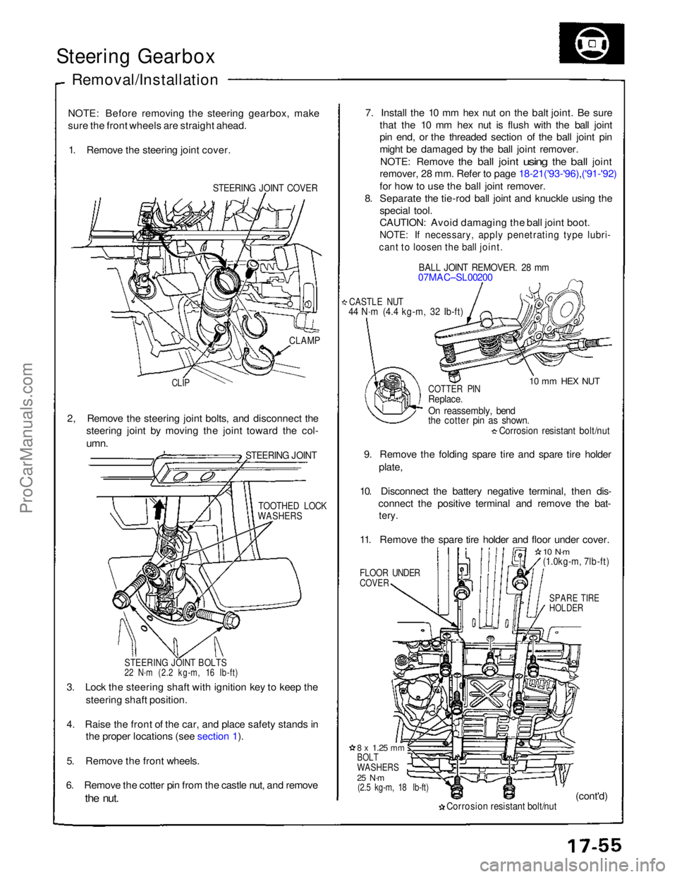
Steering Gearbox
Removal/Installation
NOTE: Before removing the steering gearbox, make
sure the front wheels are straight ahead. 1. Remove the steering joint cover.
STEERING JOINT COVER
7. Install the 10 mm hex nut on the balt joint. Be sure
that the 10 mm hex nut is flush with the ball joint
pin end, or the threaded section of the ball joint pin
might be damaged by the ball joint remover.
NOTE: Remove
the
ball
joint
using
the
ball
joint
remover, 28 mm. Refer to page 18-21('93-'96),('91-'92)
for how to use the ball joint remover.
8. Separate the tie-rod ball joint and knuckle using the
special tool.
CAUTION: Avoid damaging the ball joint boot.
NOTE: If necessary, apply penetrating type lubri-
cant to loosen the ball joint.
BALL JOINT REMOVER. 28 mm
07MAC–SL00200
CASTLE NUT
44 N·m (4.4 kg-m, 32 Ib-ft)
10 mm HEX NUT
CLAMP
CLIP
COTTER PIN
Replace.
On reassembly, bend
the cotter pin as shown.
Corrosion resistant bolt/nut
9. Remove the folding spare tire and spare tire holder plate,
10. Disconnect the battery negative terminal, then dis- connect the positive terminal and remove the bat-
tery.
11. Remove the spare tire holder and floor under cover.
FLOOR UNDER
COVER
10 N·m
(1.0kg-m, 7lb-ft)
SPARE TIRE
HOLDER
2, Remove the steering joint bolts, and disconnect the
steering joint by moving the joint toward the col-
umn.
STEERING JOINT
TOOTHED LOCK
WASHERS
STEERING JOINT BOLTS
22 N·m (2.2 kg-m, 16 Ib-ft)
3. Lock the steering shaft with ignition key to keep the steering shaft position.
4. Raise the front of the car, and place safety stands in the proper locations (see section 1).
5. Remove the front wheels.
6. Remove the cotter pin from the castle nut, and remove
the
nut.
8 x
1.25
mm
BOLT
WASHERS
25 N·m
(2.5 kg-m, 18 lb-ft)
Corrosion resistant bolt/nut
(cont'd)ProCarManuals.com
Page 438 of 1640
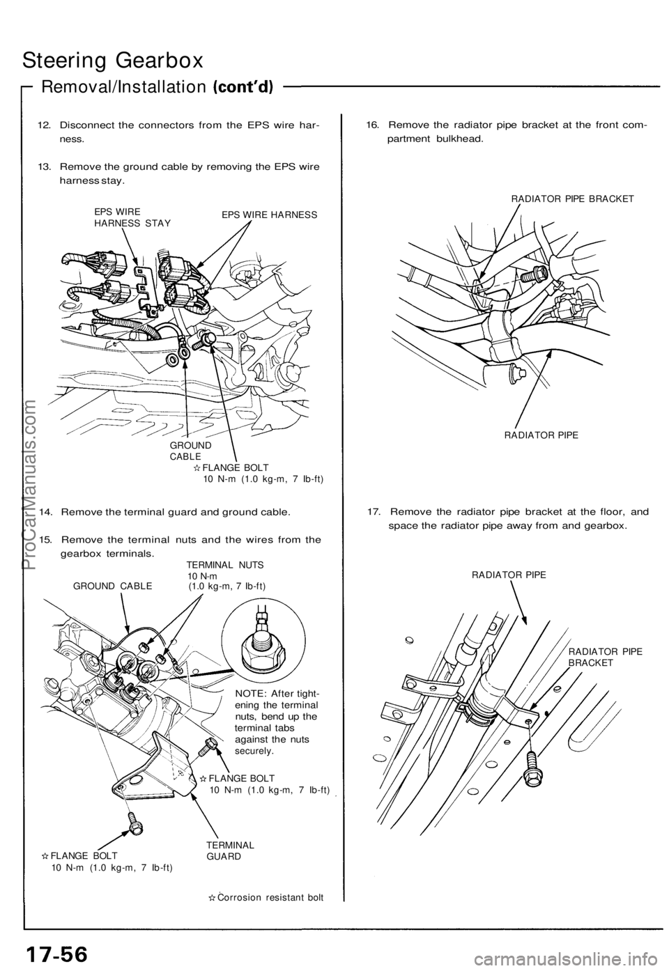
Steering Gearbo x
Removal/Installatio n
12. Disconnec t th e connector s fro m th e EP S wir e har -
ness .
13. Remov e th e groun d cabl e b y removin g th e EP S wir e
harnes s stay .
EPS WIR E
HARNES S STA Y EP
S WIR E HARNES S
GROUN D
CABLEFLANG E BOL T
1 0 N- m (1. 0 kg-m , 7 Ib-ft )
14. Remov e th e termina l guar d an d groun d cable .
15 . Remov e th e termina l nut s an d th e wire s fro m th e
gearbo x terminals .
TERMINAL NUT S10 N- mGROUN D CABL E (1.0 kg-m , 7 Ib-ft )
FLANG E BOL T
1 0 N- m (1. 0 kg-m , 7 Ib-ft )
NOTE : Afte r tight -ening th e termina lnuts, ben d u p th etermina l tab sagains t th e nut ssecurely .
FLANG E BOL T
1 0 N- m (1. 0 kg-m , 7 Ib-ft )
TERMINA L
GUAR D
Corrosio n resistan t bol t
16. Remov e th e radiato r pip e bracke t a t th e fron t com -
partmen t bulkhead .
RADIATOR PIP E BRACKE T
RADIATO R PIP E
17. Remov e th e radiato r pip e bracke t a t th e floor , an d
spac e th e radiato r pip e awa y fro m an d gearbox .
RADIATO R PIP E
RADIATO R PIP E
BRACKE T
ProCarManuals.com