Page 430 of 1640

Steering Wheel
Installation
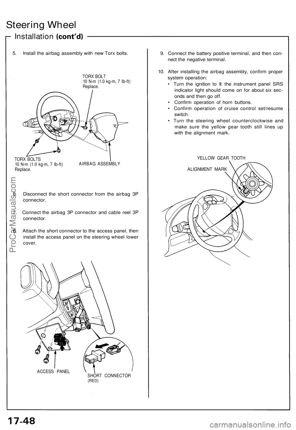
5. Install the airbag assembly with new Torx bolts.
TORX BOLT
10 N-m (1.0 kg-m, 7 Ib-ft)
Replace.
TORX BOLTS
10 N-m (1.0 kg-m, 7 Ib-ft)
Replace.
AIRBAG ASSEMBLY
6. Disconnect the short connector from the airbag 3P
connector.
7. Connect the airbag 3P connector and cable reel 3P
connector.
8. Attach the short connector to the access panel, then
install the access panel on the steering wheel lower
cover.
ACCESS PANEL
SHORT CONNECTOR
(RED)
9. Connect the battery positive terminal, and then con-
nect the negative terminal.
10. After installing the airbag assembly, confirm proper
system operation:
• Turn the ignition to II: the instrument panel SRS
indicator light should come on for about six sec-
onds and then go off.
• Confirm operation of horn buttons.
• Confirm operation of cruise control set/resume
switch.
• Turn the steering wheel counterclockwise and
make sure the yellow gear tooth still lines up
with the alignment mark.
YELLOW GEAR TOOTH
ALIGNMENT MARKProCarManuals.com
Page 863 of 1640
Side Marker/Turn Signal/Hazard Flasher System
Description
To cope with dimensional requirements for the airbag components and to offer better operational feel, the turn signal
lever and the cancel mechanism are separated mechanically, and connected electrically instead.
The system cancels the turn signals electrically, by means of a solenoid, after a turn is made. A sensor mechanism which
consists of cancel cams on the steering shaft, and a pair of switches, is used to monitor the steering shaft's position.
STEERING SHAFT
CANCEL CAM
CANCEL SWITCH
TURN SIGNAL LEVER
SOLENOIDProCarManuals.com
Page 1304 of 1640
5.
Install
the
airbag assembly
with
new
TORX
®
bolts.
TORX ®
BOLT
10 N ·
m (1.0 kg-m, 7 Ib-ft)
Replace
TORX ®
BOLTS
10 N ·
m (1.0 kg-m, 7 Ib-ft)
Replace
AIRBAG ASSEMBLY
7. Disconnect the short connector from the airbag 3-P connector.
8. Connect the airbag 3-P connector and cable reel 3-P
connector.
9. Attach the short connector to the access panel, and install the access panel on the steering wheel
lower cover.
ACCESS PANEL SHORT CONNECTOR
(RED)
10. Connect the battery positive terminal and then con-
nect the negative terminal.
11. After installing the airbag assembly, confirm proper system operation:
Turn the ignition to II: the instrument panel SRSindicator light should come on for about 6
seconds and then go off.
Confirm operation of horn buttons.
Confirm operation of cruise control set/resume
switch.
Turn the steering wheel counterclockwise and
make sure the yellow gear tooth still lines up with
the alignment mark.
YELLOW GEAR TOOTH
ALIGNMENT MARKProCarManuals.com
Page 1585 of 1640

Supplemental Restraint System (SRS)
Self-diagnosis Function
The SRS unit includes a self-diagnosis function. If there
is a failure in the sensors, SRS unit, inflator, or their cir-
cuits, the SRS light in the instrument panel goes ON.
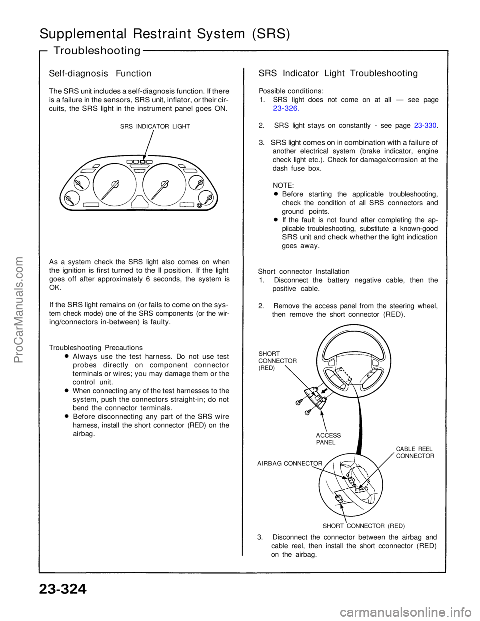
SRS INDICATOR LIGHT
As a system check the SRS light also comes on when
the ignition is first turned to the II position. If the light
goes off after approximately 6 seconds, the system is
OK.
If the SRS light remains on (or fails to come on the sys-
tem check mode) one of the SRS components (or the wir-
ing/connectors in-between) is faulty.
Troubleshooting Precautions Always use the test harness. Do not use test
probes directly on component connector
terminals or wires; you may damage them or the
control unit. When connecting any of the test harnesses to the
system, push the connectors straight-in; do not
bend the connector terminals. Before disconnecting any part of the SRS wire
harness, install the short connector (RED) on the airbag. SRS Indicator Light Troubleshooting
Possible conditions: 1. SRS light does not come on at all — see page
23-326.
2. SRS light stays on constantly - see page 23-330.
3. SRS light comes on in combination with a failure of
another electrical system (brake indicator, engine
check light etc.). Check for damage/corrosion at the
dash fuse box.
NOTE:
Before starting the applicable troubleshooting,
check the condition of all SRS connectors and
ground points. If the fault is not found after completing the ap-
plicable troubleshooting, substitute a known-good
SRS unit and check whether the light indication
goes away.
Short connector Installation 1. Disconnect the battery negative cable, then the positive cable.
2. Remove the access panel from the steering wheel, then remove the short connector (RED).
SHORT
CONNECTOR
(RED)
3. Disconnect the connector between the airbag and cable reel, then install the short cconnector (RED)
on the airbag.
Troubleshooting
SHORT CONNECTOR (RED)
AIRBAG CONNECTOR
CABLE REEL
CONNECTOR
ACCESS
PANELProCarManuals.com
Page 1588 of 1640

Steering Lock Replacement
SRS wire harness is routed near the steering lock
assembly.
CAUTION:
All SRS electrical wiring harnesses are covered with
yellow outer insulation.Before disconnecting the SRS wire harness, install
the short connector on the airbag (see page 23-323). Replace the entire affected SRS harness assembly
if it has an open circuit or damaged wiring.
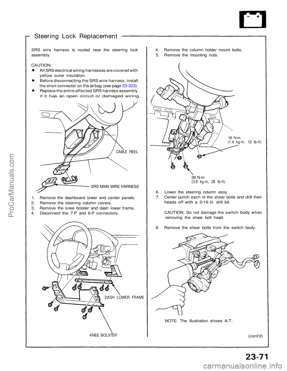
CABLE REEL
SRS MAIN WIRE HARNESS
1. Remove the dashboard lower and center panels.
2. Remove the steering column covers. 3. Remove the knee bolster and dash lower frame.
4. Disconnect the 7-P and 6-P connectors.
DASH LOWER FRAME
KNEE BOLSTER
(cont'd)
NOTE: The illustration shows A/T.
6. Lower the steering column assy.
7. Center punch each of the shear bolts and drill their
heads off with a 3/16 in. drill bit.
CAUTION: Do not damage the switch body when
removing the shear bolt head.
8. Remove the shear bolts from the switch body.
39 N·m
(3.9 kg-m, 28 Ib-ft)
16 N·m
(1.6 kg-m. 12 Ib-ft)
4. Remove the column holder mount bolts.
5. Remove the mounting nuts.ProCarManuals.com
Page 1618 of 1640
CAUTION:
All SRS electrical wiring harnesses are covered with
yellow outer insulation.
Before disconnecting the SRS wire harness, install
the short connector on the airbag (see page 23-323). Replace the entire affected SRS harness assembly
if it has an open circuit or damaged wiring.
SRS MAIN WIRE HARNESS
DEFOGGER SWITCH
Removal, page 23-273
Test, page 23-275
REAR WINDOW DEFOGGER
Function Test, page 23-288
UNDER-DASH FUSE BOX
INTEGRATED
CONTROL UNIT
DEFOGGER
RELAY
ENGINE COMPARTMENT FUSE/RELAY BOX
Description Function:
The rear window defogger is controlled by the integrated control unit.
When the defogger switch in the combination switch is pushed, it sends a signal to the defogger timer in the integrated
contro
l
unit and the defogger stays on for 25 minutes or until the ignition swi\
tch is switched off.
The indicator light in the switch shows when the defogger is on.
Rear Window Defogger
Component
Location Index
ProCarManuals.com
Page 1622 of 1640

Wipers/Washers
Windshield Wiper Motor
Replacement
1. Open the hood and remove the cap nuts and the wiper arms.
NOTE: Carefully remove the wiper arms so that they
do not touch the hood.
2. Remove the windshield lower molding, hood seal and air scoop by prying off the trim clips and removing
the screws (see page 23-281).
3. Disconnect the 5-P connector from the wiper mo- tor assembly, then remove the 2 mounting bolts and
the wiper linkage assembly.
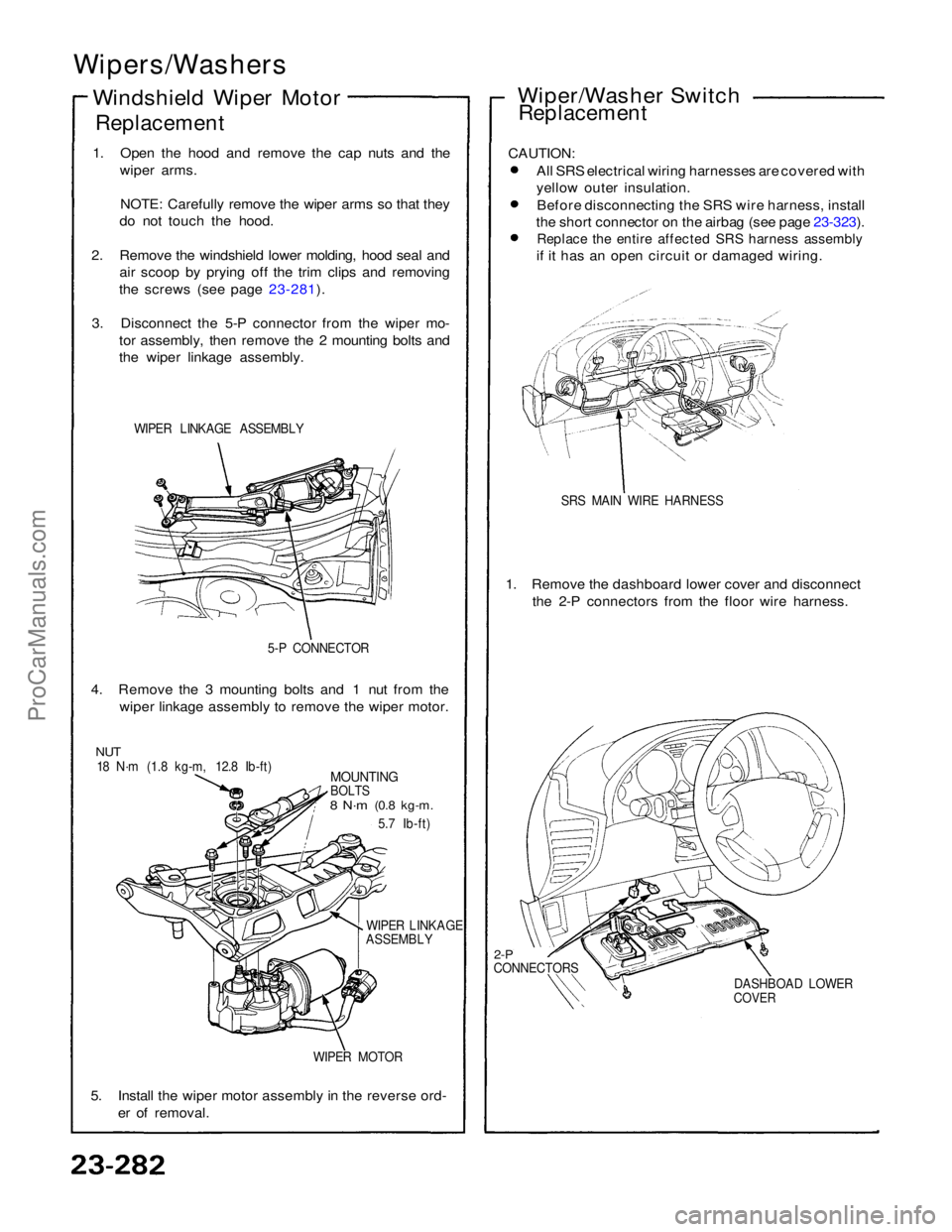
WIPER LINKAGE ASSEMBLY
5-P CONNECTOR
4. Remove the 3 mounting bolts and 1 nut from the wiper linkage assembly to remove the wiper motor.
NUT
18 N·m (1.8 kg-m, 12.8 Ib-ft)
MOUNTING
BOLTS
8 N·m
(0.8 kg-m.
5.7 Ib-ft)
WIPER LINKAGE
ASSEMBLY
WIPER MOTOR
5. Install the wiper motor assembly in the reverse ord- er of removal. Wiper/Washer Switch
Replacement
CAUTION: All SRS electrical wiring harnesses are covered with
yellow outer insulation.Before disconnecting the SRS wire harness, install
the short connector on the airbag (see page 23-323).
Replace the entire affected SRS harness assembly
if it has an open circuit or damaged wiring.
SRS MAIN WIRE HARNESS
1. Remove the dashboard lower cover and disconnect the 2-P connectors from the floor wire harness.
2-P
CONNECTORS
DASHBOAD LOWER
COVERProCarManuals.com