1991 ACURA NSX oil temperature
[x] Cancel search: oil temperaturePage 97 of 1640
![ACURA NSX 1991 Service Repair Manual
Cylinder Heads
Illustrated Index (cont'd)
CAUTION:
To
avoid
damage,
wait
until
the
engine
coolant
temperature
drops
below
100°F
(39-C]
before
removing
the
cylin-
der head.
N ACURA NSX 1991 Service Repair Manual
Cylinder Heads
Illustrated Index (cont'd)
CAUTION:
To
avoid
damage,
wait
until
the
engine
coolant
temperature
drops
below
100°F
(39-C]
before
removing
the
cylin-
der head.
N](/manual-img/32/56988/w960_56988-96.png)
Cylinder Heads
Illustrated Index (cont'd)
CAUTION:
To
avoid
damage,
wait
until
the
engine
coolant
temperature
drops
below
100°F
(39-C]
before
removing
the
cylin-
der head.
NOTE: Use new O-rings and gaskets when reassembling.
Prior to reassembling, clean all the parts in solvent, dry them, and apply lubricant to any contact parts.
REAR VARIABLE VALVE TIMING
AND VALVE LIFT ELECTRONIC CONTROL
SYSTEM (VTEC) SOLENOID VALVE
Troubleshooting, page 6-3 ('91-'93) or ('94-'96)
EXHAUST GAS
RECIRCULATI0N (EGR) VALVE
6 x 1 .0 mm
12 N·m
(1.2 kg-m.
9 Ib-ft)
8 x
1.25
mm
22 N·m
(2.2 kg-m,
16 Ib-ft)
ENGINE COOLANT
TEMPERATURE (ECT) SENSOR
18 N·m (1.8 kg-m, 13 Ib-ft)
8 x
1.25
mm
22 N·m (2.2 kg-m. 16 lb-ft)
FRONT VTEC SOLENOID VALVE
Troubleshooting. page 6-3
SEALING BOLTS
60 N·m
(6.0 kg-m,
43 lb-ft)
OIL PRESSURE
GAUSE SENDING
UNIT (section 23)
ROCKER
SHAFTS
WASHERS
Replace.
8 x
1.25
mm
22 N·m
(2.2 kg-m,16 Ib-ft)
DOWEL PIN
0-RING
Replace.
ECT SWITCH
28 N·m
12.8 kg-m.
20 lb-ft
O-RING
Replace.
O-RING
Replace.
ROCKER ARM ASSEMBLY[PRIMARY. MID, SECONDARY]
Inspection, page 6-32 ('91-'93) or ('94-'96)
ROCKER SHAFT
OIL CONTROL
ORIFICE
Remove with 5 mm
boit and clean.
FILTER
Replace.
GASKET
Replace.
O-RING
Replace.ProCarManuals.com
Page 99 of 1640
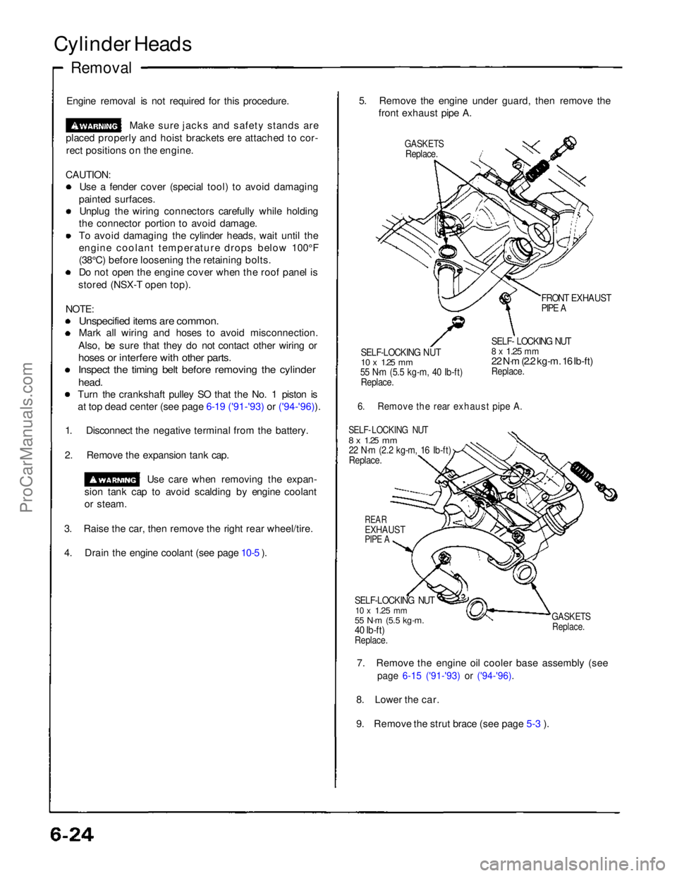
Cylinder Heads
Removal
Engine removal is not required for this procedure. Make sure jacks and safety stands are
placed properly and hoist brackets ere attached to cor- rect positions on the engine.
CAUTION: Use a fender cover (special tool) to avoid damaging
painted surfaces. Unplug the wiring connectors carefully while holding
the connector portion to avoid damage.
To avoid damaging the cylinder heads, wait until the
engine coolant temperature drops below 100°F
(38°C) before loosening the retaining bolts. Do not open the engine cover when the roof panel is
stored (NSX-T open top).
NOTE:
Unspecified items are common.
Mark all wiring and hoses to avoid misconnection.
Also, be sure that they do not contact other wiring or
hoses or interfere with other parts.
Inspect the timing belt before removing the cylinder
head.
Turn the crankshaft pulley SO that the No. 1 piston is at top dead center (see page 6-19 ('91-'93) or ('94-'96)).
1. Disconnect the negative terminal from the battery.
2. Remove the expansion tank cap. Use care when removing the expan-
sion tank cap to avoid scalding by engine coolant
or steam.
3. Raise the car, then remove the right rear wheel/tire.
4. Drain the engine coolant (see page 10-5 ). 5. Remove the engine under guard, then remove the
front exhaust pipe A.
GASKETS
Replace.
FRONT EXHAUST
PIPE A
SELF-LOCKING NUT
10 x
1.25
mm
55 N·m (5.5 kg-m, 40 Ib-ft)
Replace.
SELF- LOCKING NUT
8 x
1.25
mm
22 N·m (2.2 kg-m. 16 Ib-ft)
Replace.
6. Remove the rear exhaust pipe A.
SELF- LOCKING NUT
8 x
1.25
mm
22 N·m (2.2 kg-m, 16 Ib-ft)
Replace.
REAR
EXHAUST
PIPE A
SELF-LOCKING NUT
10 x
1.25
mm
55 N·m (5.5 kg-m.
40 Ib-ft)
Replace.
GASKETS
Replace.
7. Remove the engine oil cooler base assembly (see
page 6-15 ('91-'93) or ('94-'96).
8. Lower the car.
9. Remove the strut brace (see page 5-3 ).ProCarManuals.com
Page 102 of 1640

24. Remove the engine wire harness connectors and
wire harness clamps from the cylinder head and
intake manifold, Six injector connectors
Intake air temperature (IAT) sensor connector
CKP/CYP sensor connector
Heated oxygen sensor (HO2S) connectors
Ignition control module (ICM) connectors
Engine coolant temperature (ECT) sensor connec-
tor
ECT gauge sending unit connector
ECT switch connector
Exhaust gas recirculation (EGR) valve lift sensor
connector
Throttle position sensor connector Engine oil pressure gauge sending unit connector
Knock sensor connector
VTEC solenoid valve connectors
VTEC pressure switch connectors
Engine oil pressure switch connector
Alternator connector
Alternator terminal
Throttle body 6P connector
25. Remove the ignition coils and connector.
26. Remove the EGR pipe and intake manifold assem- bly.
8 x 1.25mm
22 N·m (2.2 kg-m, 16 Ib-ft)
6 x 1.0 mm
12 N·m
(1.2 kg-m,
9 lb-ft)
GASKETS
Replace. INTAKE
MANIFOLD
ASSEMBLY
GASKET
Replace.
27. Loosen the adjusting nut and idler pulley center nut,
then remove the air conditioning compressor belt
(see page 6-17('91-'93) or ('94-'96)).
28. Remove the cover, adjusting bolt, mounting bolt and mounting nut, then remove the alternator belt
and alternator.
COVER
MOUNTING BOLT
10 x
1.25
mm
45 N·m (4.5 kg·m,
33 Ib-ft)
MOUNTING NUT
10 x
1.25
mm
45 N·m (4.5 kg·m.
33 Ib·ft)
ALTERNATOR
BELT
29. Disconnect the knock sensor connector, then remove
the wire holder.
6 x 1.0 mm
12N·m (1.2 kg-m, 9 Ib-ft)
KNOCK SENSOR
WIRE HOLDER
(cont'd)
6 x 1.0 mm
12 N·m (1.2 kg-m, 9 Ib-ft)
ADJUSTING
BOLTProCarManuals.com
Page 146 of 1640
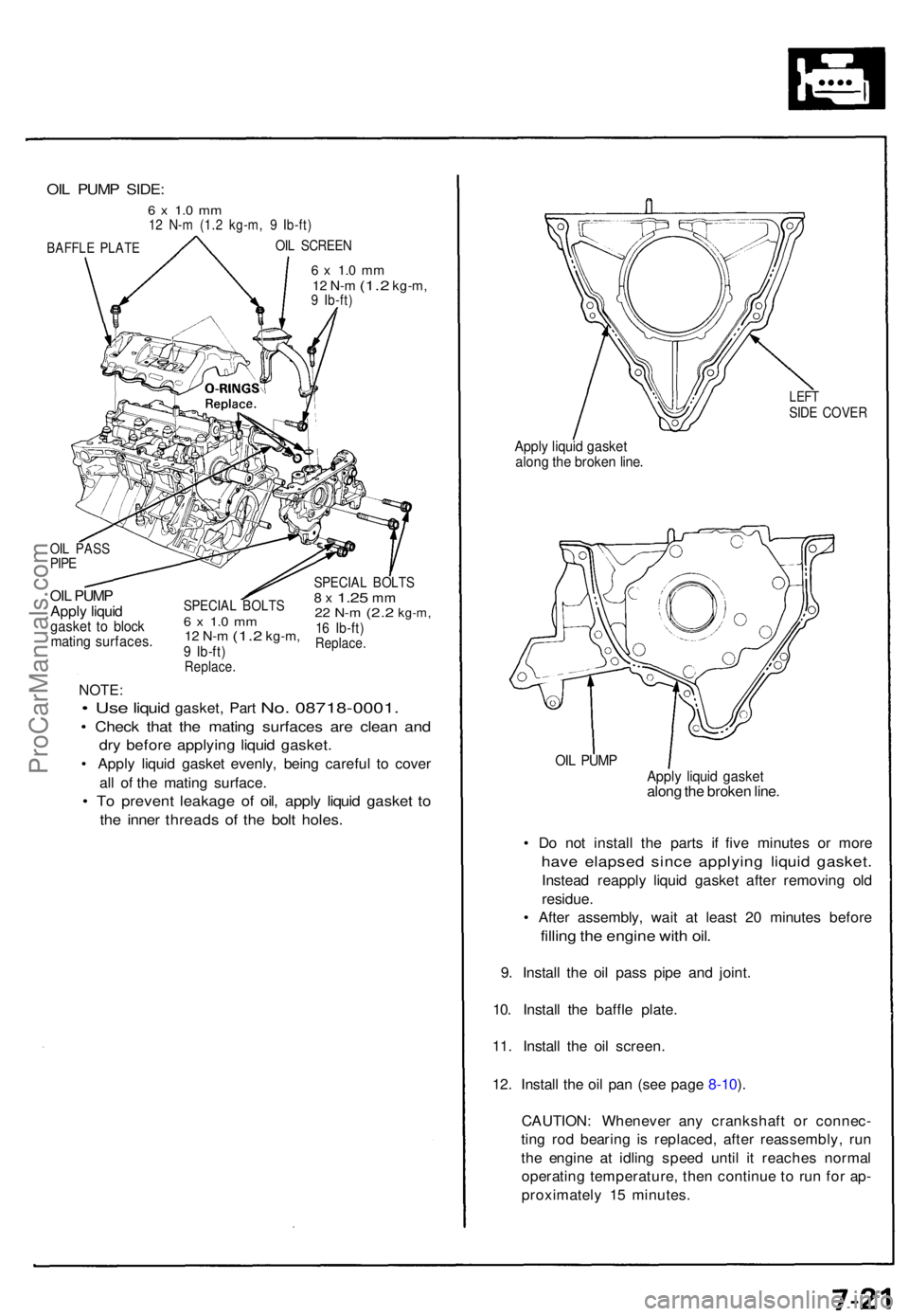
6 x 1. 0 m m12 N- m (1. 2 kg-m ,9 Ib-ft )
OIL PUM P
Appl y liqui d
gaske t t o bloc kmatin g surfaces .
SPECIAL BOLT S6 x 1. 0 m m12 N- m (1. 2 kg-m ,9 Ib-ft )Replace .
SPECIAL BOLT S8 x 1.2 5 mm22 N- m (2. 2 kg-m ,16 Ib-ft )Replace .
NOTE:
• Use liqui d gasket , Par t No. 08718-0001 .
• Chec k tha t th e matin g surface s ar e clea n an d
dry befor e applyin g liqui d gasket .
• Appl y liqui d gaske t evenly , bein g carefu l t o cove r
al l o f th e matin g surface .
• T o preven t leakag e o f oil , appl y liqui d gaske t t o
th e inne r thread s of the bol t holes .
LEFTSIDE COVE R
Apply liqui d gaske talong th e broke n line .
OIL PUM PApply liqui d gaske talong th e broke n line .
• D o no t instal l th e part s i f fiv e minute s o r mor e
have elapse d sinc e applyin g liqui d gasket .
Instead reappl y liqui d gaske t afte r removin g ol d
residue .
• Afte r assembly , wai t a t leas t 2 0 minute s befor e
filling th e engin e wit h oil .
9. Instal l th e oi l pas s pip e an d joint .
10 . Instal l th e baffl e plate .
11 . Instal l th e oi l screen .
12 . Instal l th e oi l pa n (se e pag e 8-10 ).
CAUTION : Wheneve r an y crankshaf t o r connec -
tin g ro d bearin g i s replaced , afte r reassembly , ru n
th e engin e a t idlin g spee d unti l i t reache s norma l
operatin g temperature , the n continu e t o ru n fo r ap -
proximatel y 1 5 minutes .
OIL PUM P SIDE :
6 x 1. 0 m m12 N- m (1. 2 kg-m , 9 Ib-ft )
OIL SCREE NBAFFLE PLAT E
OIL PAS SPIPE
ProCarManuals.com
Page 763 of 1640
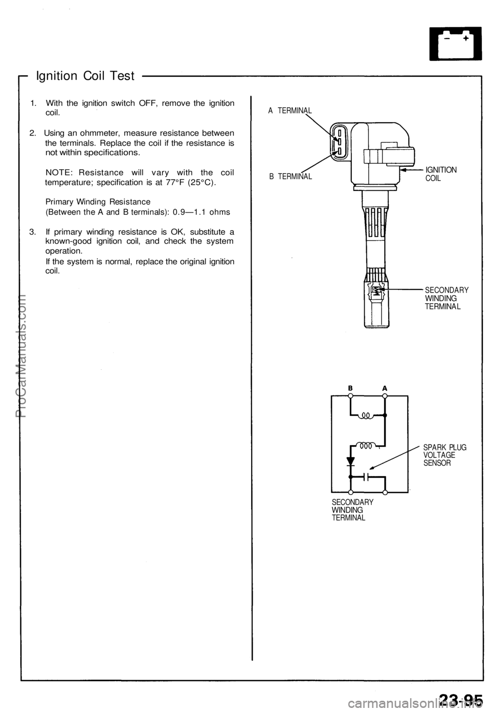
Ignition Coil Test
1. With the ignition switch OFF, remove the ignition
coil.
2. Using an ohmmeter, measure resistance between
the terminals. Replace the coil if the resistance is
not within specifications.
NOTE: Resistance will vary with the coil
temperature; specification is at 77°F (25°C).
Primary Winding Resistance
(Between the A and B terminals): 0.9—1.1 ohms
3. If primary winding resistance is OK, substitute a
known-good ignition coil, and check the system
operation.
If the system is normal, replace the original ignition
coil.
A TERMINAL
B TERMINAL
IGNITION
COIL
SECONDARY
WINDING
TERMINAL
SPARK PLUG
VOLTAGE
SENSOR
SECONDARY
WINDING
TERMINALProCarManuals.com
Page 786 of 1640
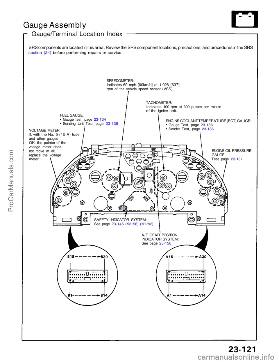
Gauge Assembly
Gauge/Terminal Location Index
SRS components are located in this area. Review the SRS component locations, precautions, and procedures in the SRS
section (24) before performing repairs or service.
SPEEDOMETER:
Indicates 60 mph [60km/h] at 1.026 [637]
rpm of the vehicle speed sensor (VSS).
FUEL GAUGE: Gauge test, page 23-134 Sending Unit Test, page 23-135
VOLTAGE METER:
If, with the No. 5 (15 A) fuse
and other gauges
OK, the pointer of the
voltage meter does not move at all,
replace the voltage
meter.
SAFETY INDICATOR SYSTEM:
See page 23-145 ('93-'96) ('91-'92)A/T GEAR POSITION
INDICATOR SYSTEM:
See page 23-156 ENGINE OIL PRESSURE
GAUGE:
Test page 23-137
ENGINE COOLANT TEMPERATURE (ECT) GAUGE:
Gauge Test, page 23-136 Sender Test, page 23-136
TACHOMETER:
Indicates 100 rpm at 300 pulses per minute
of the igniter unit.ProCarManuals.com
Page 790 of 1640
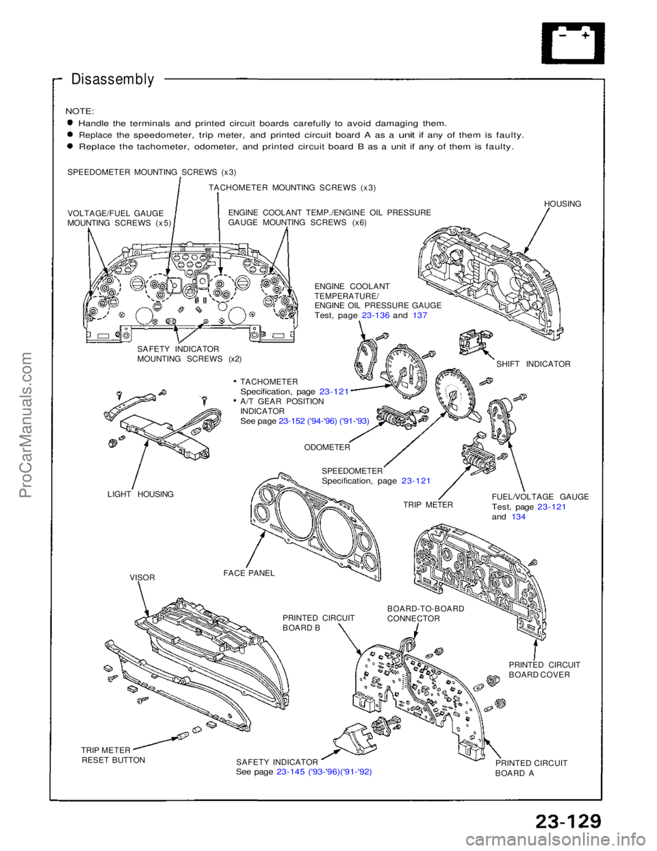
Disassembly
NOTE:
Handle the terminals and printed circuit boards carefully to avoid damaging them.
Replace
the
speedometer,
trip
meter,
and
printed
circuit
board
A as a
unit
if any of
them
is
faulty. Replace the tachometer, odometer, and printed circuit board B as a unit if any of them is faulty.
SPEEDOMETER MOUNTING SCREWS (x3) TACHOMETER MOUNTING SCREWS (x3)
VOLTAGE/FUEL GAUGE
MOUNTING SCREWS (x5) ENGINE COOLANT TEMP./ENGINE OIL PRESSURE
GAUGE MOUNTING SCREWS (x6)
HOUSING
ENGINE COOLANT
TEMPERATURE/
ENGINE OIL PRESSURE GAUGE
Test, page 23-136 and 137
SAFETY INDICATOR
MOUNTING SCREWS (x2) SHIFT INDICATOR
TACHOMETER
Specification, page 23-121
A/T GEAR POSITION
INDICATOR
See page 23-152 ('94-'96) ('91-'93)
LIGHT HOUSING
ODOMETER
SPEEDOMETER
Specification, page 23-121
TRIP METER FUEL/VOLTAGE GAUGE
Test, page 23-121
and 134
FACE PANEL PRINTED CIRCUIT
BOARD B
BOARD-TO-BOARD
CONNECTOR
PRINTED CIRCUIT
BOARD COVER
PRINTED CIRCUIT
BOARD A
SAFETY INDICATOR
See page 23-145 ('93-'96)('91-'92)
TRIP METER
RESET BUTTON
VISORProCarManuals.com
Page 965 of 1640
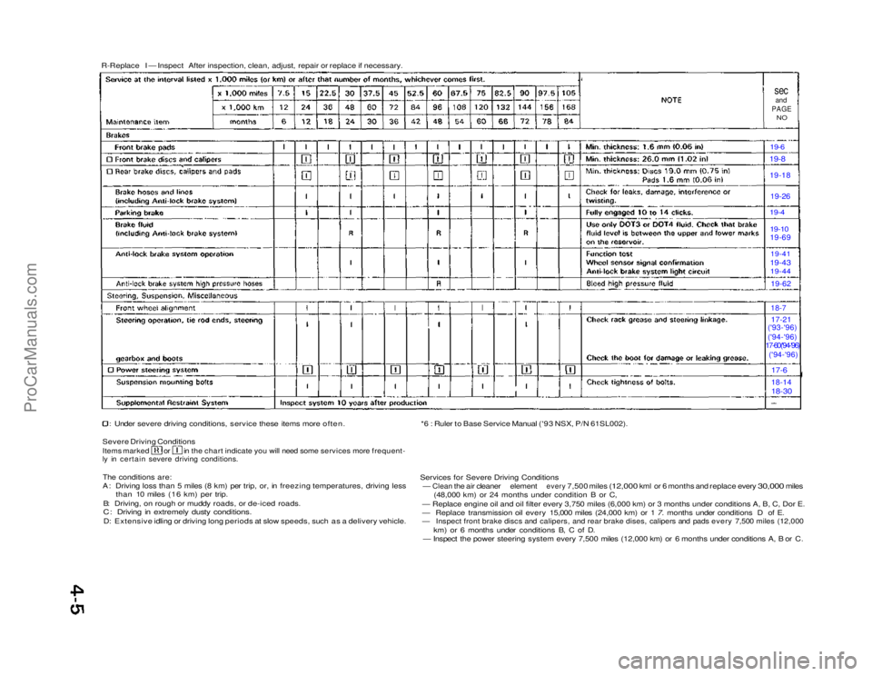
R-Replace I — Inspect After inspection, clean, adjust, repair or replace if necessary.
sec
and
PAGE
NO
19-6 19-8
19-18
19-26
19-4
19-10
19-69
19-41
19-43 19-44
19-62
18-7
17-21
('93-'96)
('94-'96)
17-60('94-'96)
('94-'96)
17-6
18-14
18-30
Under severe driving conditions, service these items more often.
Severe Driving Conditions
Items marked or in the chart indicate you will need some services more frequent-
ly in certain severe driving conditions.
The conditions are:
A: Driving loss than 5 miles (8 km) per trip, or, in freezing temperatures, driving less than 10 miles (16 km) per trip.
B: Driving, on rough or muddy roads, or de-iced roads.
C: Driving in extremely dusty conditions.
D: Extensive idling or driving long periods at slow speeds, such as a delivery vehicle. *6 : Ruler to Base Service Manual ('93 NSX, P/N 61SL002).
Services for Severe Driving Conditions
—
Clean
the air
cleaner
element
every
7,500 miles
(12,000
kml or 6
months
and
replace every
30,000
miles (48,000 km) or 24 months under condition B or C,
— Replace engine oil and oil filter every 3,750 miles (6,000 km) or\
3 months under conditions A, B, C, Dor E.
— Replace transmission oil every 15,000 miles (24,000 km) or 1 7. months under conditions D of E.
— Inspect front brake discs and calipers, and rear brake dises, calipers and pads every 7,500 miles (12,000
km) or 6 months under conditions B, C of D.
— Inspect the power steering system every 7,500 miles (12,000 km) or 6 months under conditions A, B or C.ProCarManuals.com