1991 ACURA NSX air filter
[x] Cancel search: air filterPage 72 of 1640
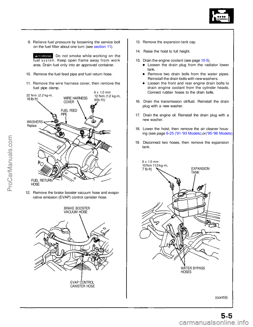
9. Relieve fuel pressure by loosening the service bolt
on the fuel filter about one turn (see section 11).
Do not smoke while working on the
fuel
system.
Keep open flame away from work
area. Drain fuel only into an approved container.
10. Remove the fuel feed pipe and fuel return hose.
11. Remove the wire harness cover, then remove the fuel pipe clamp.
22 N·m
(2.2 kg-m,
16 Ib-ft)
WIRE HARNESS
COVER
6 x 1.0 mm
12 N·m
(1.2 kg-m,
9 lb-ft)
FUEL FEED
PIPE
WASHERS
Replace.
FUEL RETURN
HOSE
12. Remove the brake booster vacuum hose and evapo- rative emission (EVAP) control canister hose.
BRAKE BOOSTER
VACUUM HOSE
EVAP CONTROL
CANISTER HOSE
13. Remove the expansion tank cap.
14. Raise the hoist to full height.
15. Drain the engine coolant (see page
10-5).
Loosen the drain plug from the radiator lower
tank. Remove two drain bolls from the water pipes.
Reinstall the drain bolts with new washers.
Loosen the front and rear engine drain bolts to
drain engine coolant from the cylinder heads.
Connect rubber hoses to the drain bolts.
16. Drain the transmission oil/fluid. Reinstall the drain plug with a new washer.
17. Drain the engine oil. Reinstall the drain plug with a
new washer.
18. Lower the hoist, then remove the air cleaner hous-
ing (see page 6-25 ('91-'93 Mode ls),or('95-'96 Models).
19. Disconnect two hoses, then remove the expansion
tank.
6 x 1.0 mm
10 N·m
11.0 kg-m,
7 lb-ft)
EXPANSION
TANK
WATER BYPASS
HOSES
(cont'd)ProCarManuals.com
Page 100 of 1640
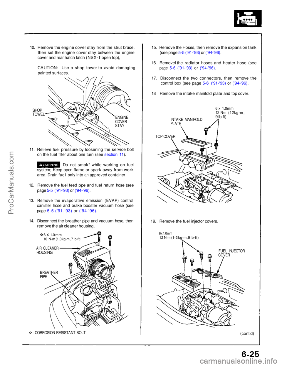
10. Remove the engine cover stay from the strut brace,
then set the engine cover stay between the engine
cover and rear hatch latch (NSX-T open top),
CAUTION: Use a shop tower to avoid damaging
painted surfaces.
SHOP
TOWEL
11. Relieve fuel pressure by loosening the service bolt on the fuel filter about one turn (see section 11).
Do not smok* while working on fuel
system; Keep open flame or spark away from work
area. Drain fue1 only into an approved container.
12. Remove the fuel feed pipe and fuel return hose (see page 5-5 ('91-'93) or ('94-'96).
13. Remove the evaporative emission (EVAP) control
canister hose and brake booster vacuum hose (see
page 5-5 ('91-'93) or ('94-'96).
14. Disconnect the breather pipe and vacuum hose, then remove the air cleaner housing.
6 x 1.0 mm
10 N·m (1.0 kg-m, 7 lb-ftl
AIR CLEANER
HOUSING
BREATHER
PIPE
: CORROSION RESISTANT BOLT
15. Remove the Hoses, then remove the expansion tank
(see page 5-5 ('91-'93) or ('94-'96).
16. Removel the radiator hoses and heater hose (see
page 5-6 ('91-'93) or ('94-'96).
17. Disconnect the two connectors, then remove the
control box (see page 5-6 ('91-'93) or ('94-'96).
18. Remove the intake manifold plate and top cover.
INTAKE MANIFOLD
PLATE
6 x
1.0mm
12 N·m (12kg-m,
9 lb-ft)
TOP COVER
19. Remove the fuel injector covers.
6 x 1.0 mm
12 N·m (1-2 kg-m, 9 lb-ft)
FUEL INJECTOR
COVER
(cont'd)
ENGINE
COVER
STAYProCarManuals.com
Page 678 of 1640
('93-'96), 86 ('91-'92 Models)
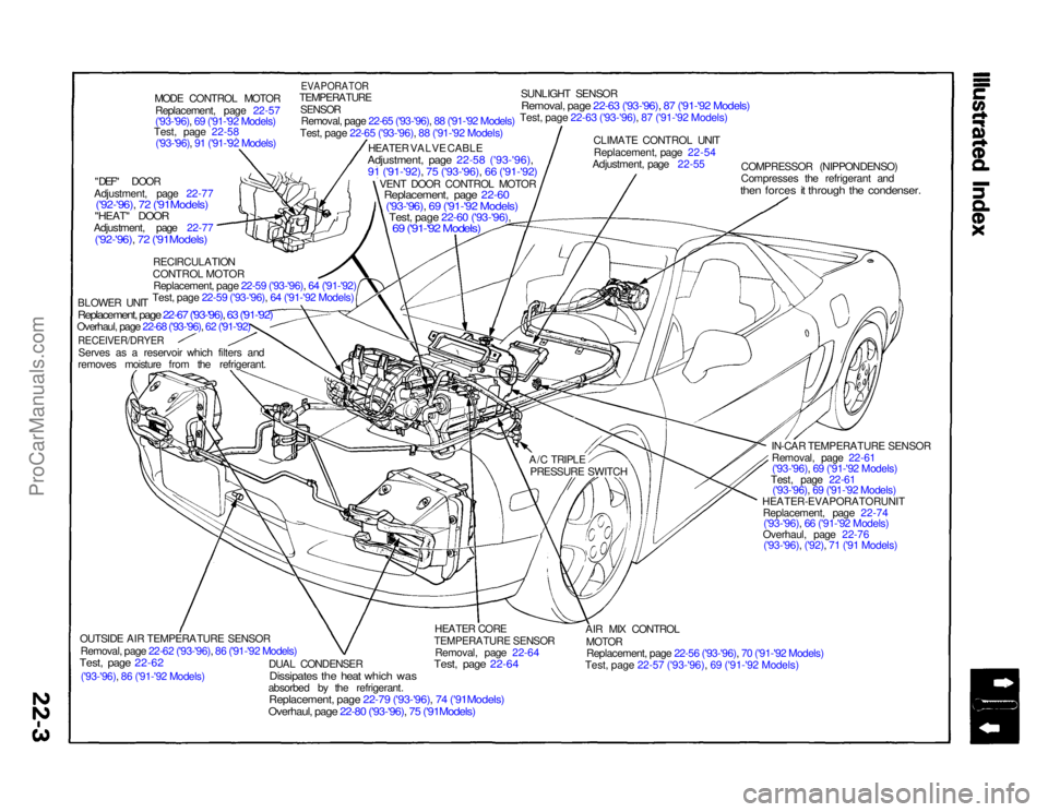
MODE CONTROL MOTOR
Replacement, page 22-57
('93-'96), 69 ('91-'92 Models)
Test, page 22-58
('93-'96), 91 ('91-'92 Models)
"DEF" DOOR
Adjustment, page 22-77
('92-'96), 72 ('91Models)
"HEAT" DOOR
Adjustment, page 22-77
('92-'96), 72 ('91Models)
RECIRCULATION
CONTROL MOTOR
Replacement, page 22-59 ('93-'96), 64 ('91-'92)
Test, page 22-59 ('93-'96), 64 ('91-'92 Models)
BLOWER UNIT
Replacement, page 22-67 ('93-'96), 63 ('91-'92)Overhaul, page 22-68 ('93-'96), 62 ('91-'92)
RECEIVER/DRYER
Serves as a reservoir which filters and
removes moisture from the refrigerant.
OUTSIDE AIR TEMPERATURE SENSOR
Removal, page 22-62 ('93-'96), 86 ('91-'92 Models)
Test, page 22-62
DUAL CONDENSER
Dissipates the heat which was
absorbed by the refrigerant.
Replacement, page 22-79 ('93-'96), 74 ('91Models)Overhaul, page 22-80 ('93-'96), 75 ('91Models)
HEATER CORE
TEMPERATURE SENSOR
Removal, page 22-64
Test, page 22-64
AIR MIX CONTROL
MOTOR
Replacement, page 22-56 ('93-'96), 70 ('91-'92 Models)
Test, page 22-57 ('93-'96), 69 ('91-'92 Models)
HEATER-EVAPORATORUNIT
Replacement, page 22-74('93-'96), 66 ('91-'92 Models)
Overhaul, page 22-76 ('93-'96), ('92), 71 ('91 Models) IN-CAR TEMPERATURE SENSOR
Removal, page 22-61('93-'96), 69 ('91-'92 Models)
Test, page 22-61 ('93-'96), 69 ('91-'92 Models)
COMPRESSOR (NIPPONDENSO)
Compresses the refrigerant and
then forces it through the condenser.
CLIMATE CONTROL UNIT
Replacement, page 22-54
Adjustment, page 22-55
SUNLIGHT SENSOR
Removal, page 22-63 ('93-'96), 87 ('91-'92 Models)Test, page 22-63 ('93-'96), 87 ('91-'92 Models)
EVAPORATOR
TEMPERATURE
SENSOR
Removal, page 22-65 ('93-'96), 88 ('91-'92 Models)
Test, page 22-65 ('93-'96), 88 ('91-'92 Models)
HEATER VALVE CABLE
Adjustment, page 22-58 ('93-'96),
91 ('91-'92), 75 ('93-'96), 66 ('91-'92)
VENT DOOR CONTROL MOTOR
Replacement, page 22-60
('93-'96)
, 69 ('91-'92 Models)
Test, page 22-60 ('93-'96),
69 ('91-'92 Models)
A/C TRIPLE
PRESSURE SWITCHProCarManuals.com
Page 965 of 1640
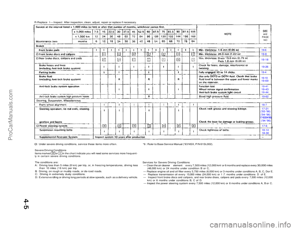
R-Replace I — Inspect After inspection, clean, adjust, repair or replace if necessary.
sec
and
PAGE
NO
19-6 19-8
19-18
19-26
19-4
19-10
19-69
19-41
19-43 19-44
19-62
18-7
17-21
('93-'96)
('94-'96)
17-60('94-'96)
('94-'96)
17-6
18-14
18-30
Under severe driving conditions, service these items more often.
Severe Driving Conditions
Items marked or in the chart indicate you will need some services more frequent-
ly in certain severe driving conditions.
The conditions are:
A: Driving loss than 5 miles (8 km) per trip, or, in freezing temperatures, driving less than 10 miles (16 km) per trip.
B: Driving, on rough or muddy roads, or de-iced roads.
C: Driving in extremely dusty conditions.
D: Extensive idling or driving long periods at slow speeds, such as a delivery vehicle. *6 : Ruler to Base Service Manual ('93 NSX, P/N 61SL002).
Services for Severe Driving Conditions
—
Clean
the air
cleaner
element
every
7,500 miles
(12,000
kml or 6
months
and
replace every
30,000
miles (48,000 km) or 24 months under condition B or C,
— Replace engine oil and oil filter every 3,750 miles (6,000 km) or\
3 months under conditions A, B, C, Dor E.
— Replace transmission oil every 15,000 miles (24,000 km) or 1 7. months under conditions D of E.
— Inspect front brake discs and calipers, and rear brake dises, calipers and pads every 7,500 miles (12,000
km) or 6 months under conditions B, C of D.
— Inspect the power steering system every 7,500 miles (12,000 km) or 6 months under conditions A, B or C.ProCarManuals.com
Page 976 of 1640
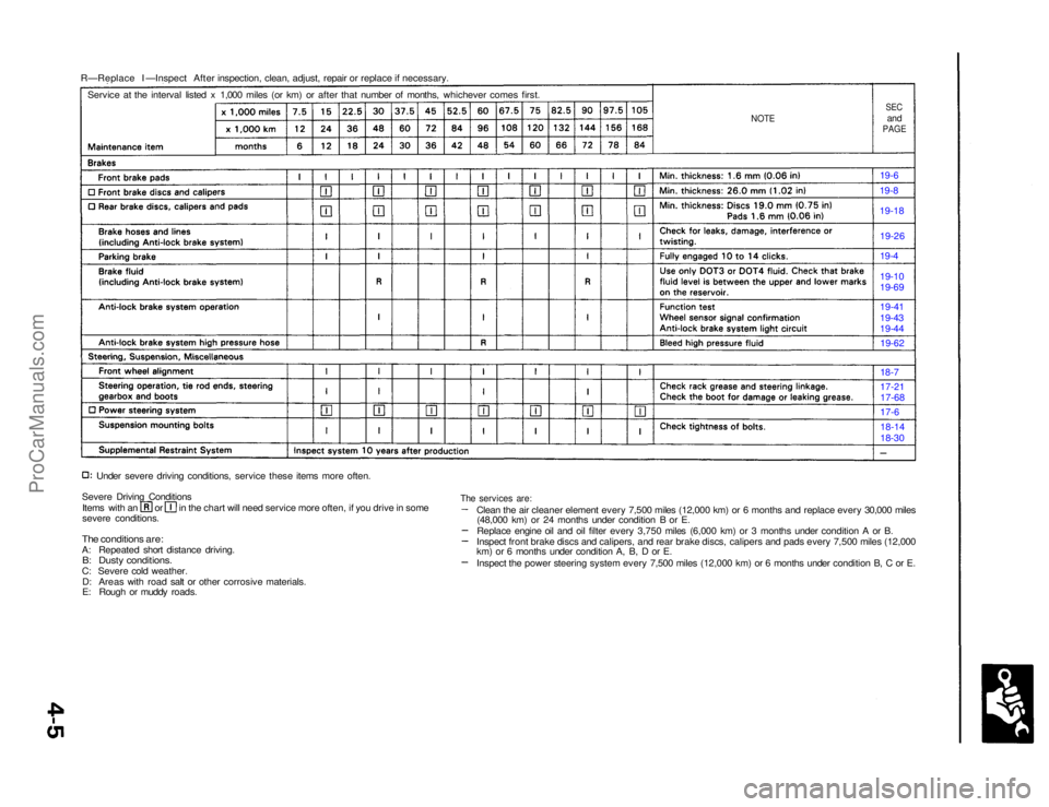
R—Replace I —Inspect After inspection, clean, adjust, repair or replace if necessary.
NOTE
SEC
and
PAGE
Service at the interval listed x 1,000 miles (or km) or after that number of months, whichever comes first.
19-6
19-8
19-18
Under severe driving conditions, service these items more often.
Severe Driving Conditions Items with an or in the chart will need service more often, if you drive in some
severe conditions.
The conditions are:
A: Repeated short distance driving.
B: Dusty conditions.
C: Severe cold weather. D: Areas with road salt or other corrosive materials.
E: Rough or muddy roads. 18-14
18-30
17-6
17-21
17-68
18-7
19-62
19-41
19-43
19-44 19-10
19-69 19-4
19-26
The services are:
Clean the air cleaner element every 7,500 miles (12,000 km) or 6 months and replace every 30,000 miles(48,000 km) or 24 months under condition B or E.
Replace engine oil and oil filter every 3,750 miles (6,000 km) or 3 months under condition A or B.
Inspect front brake discs and calipers, and rear brake discs, calipers and pads every 7,500 miles (12,000
km) or 6 months under condition A, B, D or E.
Inspect the power steering system every 7,500 miles (12,000 km) or 6 months under condition B, C or E.ProCarManuals.com
Page 1054 of 1640
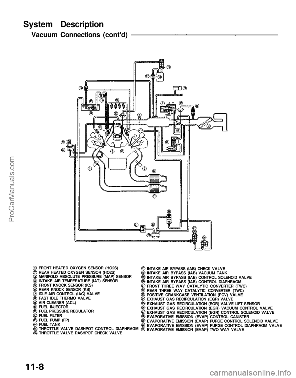
System Description
Vacuum Connections (cont'd)
FRONT HEATED OXYGEN SENSOR (HO2S)
REAR HEATED OXYGEN SENSOR (HO2S)
MANIFOLD ABSOLUTE PRESSURE (MAP) SENSORINTAKE AIR TEMPERATURE (IAT) SENSOR
FRONT KNOCK SENSOR (KS)
REAR KNOCK SENSOR (KS) IDLE AIR CONTROL (IAC) VALVE
FAST IDLE THERMO VALVE
AIR CLEANER (ACL) FUEL INJECTORFUEL PRESSURE REGULATOR
FUEL FILTER
FUEL PUMP (FP)
FUEL TANK
THROTTLE VALVE DASHPOT CONTROL DIAPHRAGM
THROTTLE VALVE DASHPOT CHECK VALVE INTAKE AIR BYPASS (IAB) CHECK VALVE
INTAKE AIR BYPASS (IAB) VACUUM TANK
INTAKE AIR BYPASS (IAB) CONTROL SOLENOID VALVE
INTAKE AIR BYPASS (IAB) CONTROL DIAPHRAGM
FRONT THREE WAY CATALYTIC CONVERTER (TWC)
REAR THREE WAY CATALYTIC CONVERTER (TWC)
POSITIVE CRANKCASE VENTILATION (PCV) VALVE
EXHAUST GAS RECIRCULATION (EGR) VALVE
EXHAUST GAS RECIRCULATION (EGR) VALVE LIFT SENSOR
EXHAUST GAS RECIRCULATION (EGR) VACUUM CONTROL VALVE
EXHAUST GAS RECIRCULATION (EGR) CONTROL SOLENOID VALVE
EVAPORATIVE EMISSION (EVAP) CONTROL CANISTER
EVAPORATIVE EMISSION (EVAP) PURGE CONTROL SOLENOID VALVE
EVAPORATIVE EMISSION (EVAP) PURGE CONTROL DIAPHRAGM VALVE
EVAPORATIVE EMISSION (EVAP) TWO WAY VALVEProCarManuals.com
Page 1229 of 1640
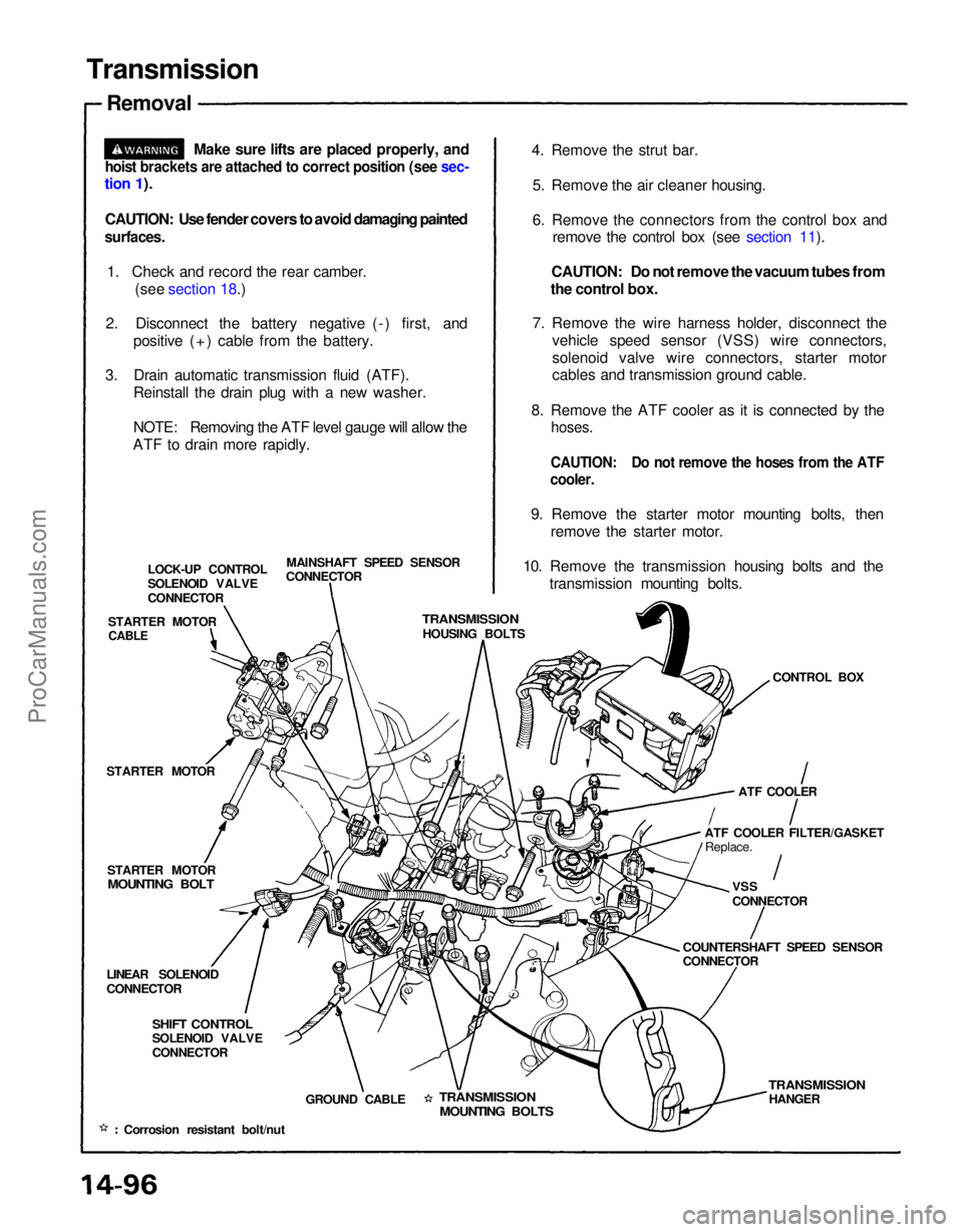
Transmission
Removal
Make sure lifts are placed properly, and
hoist brackets are attached to correct position (see sec-
tion 1).
CAUTION: Use fender covers to avoid damaging painted
surfaces.
1. Check and record the rear camber. (see section 18.)
2. Disconnect the battery negative (-) first, and positive (+) cable from the battery.
3. Drain automatic transmission fluid (ATF). Reinstall the drain plug with a new washer.
NOTE: Removing the ATF level gauge will allow the
ATF to drain more rapidly. 4. Remove the strut bar.
5. Remove the air cleaner housing.
6. Remove the connectors from the control box and remove the control box (see section 11).
CAUTION: Do not remove the vacuum tubes from
the control box.
7. Remove the wire harness holder, disconnect the vehicle speed sensor (VSS) wire connectors,
solenoid valve wire connectors, starter motor
cables and transmission ground cable.
8. Remove the ATF cooler as it is connected by the
hoses.
CAUTION: Do not remove the hoses from the ATF
cooler.
9. Remove the starter motor mounting bolts, then remove the starter motor.
10. Remove the transmission housing bolts and the transmission mounting bolts.
MAINSHAFT SPEED SENSOR
CONNECTOR
LOCK-UP CONTROL
SOLENOID VALVE
CONNECTOR
STARTER MOTOR
TRANSMISSION
HOUSING BOLTS
CONTROL BOX
STARTER MOTOR
STARTER MOTOR
MOUNTING BOLT
ATF COOLER
ATF COOLER FILTER/GASKET Replace.
VSS
CONNECTOR
COUNTERSHAFT SPEED SENSOR
CONNECTOR
LINEAR SOLENOID
CONNECTOR
SHIFT CONTROL
SOLENOID VALVE
CONNECTOR
GROUND CABLE
TRANSMISSION
MOUNTING BOLTS
TRANSMISSION
HANGER
Corrosion resistant bolt/nut
CABLEProCarManuals.com
Page 1247 of 1640
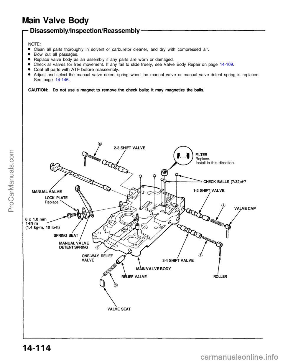
VALVE SEAT
ROLLER
RELIEF VALVE
MAIN VALVE BODY 3-4 SHIFT VALVE VALVE CAP
1-2 SHIFT VALVE
CHECK BALLS (7/32) 7
FILTER
Replace.
Install in this direction.
2-3 SHIFT VALVE
ONE-WAY RELIEF
VALVE
MANUAL VALVE
DETENT SPRING
SPRING SEAT
6 x 1.0 mm
MANUAL VALVE
Replace.
Main Valve Body
Disassembly/Inspection/Reassembly
Clean all parts thoroughly in solvent or carburetor cleaner, and dry with compressed air.
Blow out all passages.
Replace valve body as an assembly if any parts are worn or damaged.
Check all valves for free movement. If any fail to slide freely, see Valve Body Repair on page 14-109.
Coat all parts with ATF before reassembly.
Adjust and select the manual valve detent spring when the manual valve or manual valve detent spring is replaced.See page 14-146.
LOCK PLATE
14N .
m
(1.4 kg-m, 10 Ib-ft)
NOTE:
CAUTION: Do not use a magnet to remove the check balls; it may magnetize the balls.ProCarManuals.com