1991 ACURA NSX jump start
[x] Cancel search: jump startPage 230 of 1640
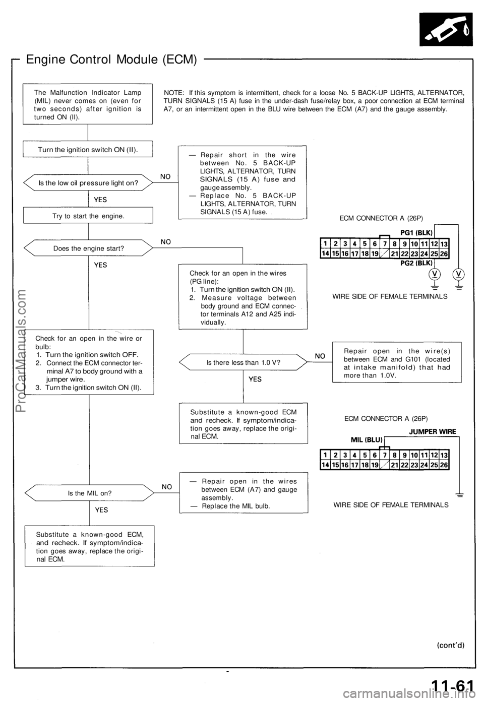
Engine Control Module (ECM)
NOTE: If this symptom is intermittent, check for a loose No. 5 BACK-UP LIGHTS, ALTERNATOR,
TURN SIGNALS (15 A) fuse in the under-dash fuse/relay box, a poor connection at ECM terminal
A7, or an intermittent open in the BLU wire between the ECM (A7) and the gauge assembly.
Is the low oil pressure light on?
Try to start the engine.
Does the engine start?
Check for an open in the wire or
bulb:
1. Turn the ignition switch OFF.
2. Connect the ECM connector ter-
minal A7 to body ground with a
jumper wire.
3. Turn the ignition switch ON (II).
Is the MIL on?
Substitute a known-good ECM,
and recheck. If symptom/indica-
tion goes away, replace the origi-
nal
ECM.
— Repair short in the wire
between No. 5 BACK-UP
LIGHTS, ALTERNATOR, TURN
SIGNALS (15 A) fuse and
gauge assembly.
— Replace No. 5 BACK-UP
LIGHTS, ALTERNATOR, TURN
SIGNALS (15 A) fuse.
ECM CONNECTOR A (26P)
Check for an open in the wires
(PG line):
1. Turn the ignition switch ON (II).
2. Measure voltage between
body ground and ECM connec-
tor terminals A12 and A25 indi-
vidually.
WIRE SIDE OF FEMALE TERMINALS
Is there less than 1.0 V?
Repair open in the wire(s)
between ECM and G101 (located
at intake manifold) that had
more than 1.0V.
— Repair open in the wires
between ECM (A7) and gauge
assembly.
— Replace the MIL bulb.
WIRE SIDE OF FEMALE TERMINALS
ECM CONNECTOR A (26P)
Substitute a known-good ECM
and recheck. If symptom/indica-
tion goes away, replace the origi-
nal
ECM.
Turn the ignition switch ON (II).
The Malfunction Indicator Lamp
(MIL) never comes on (even for
two seconds) after ignition is
turned ON (II).ProCarManuals.com
Page 261 of 1640
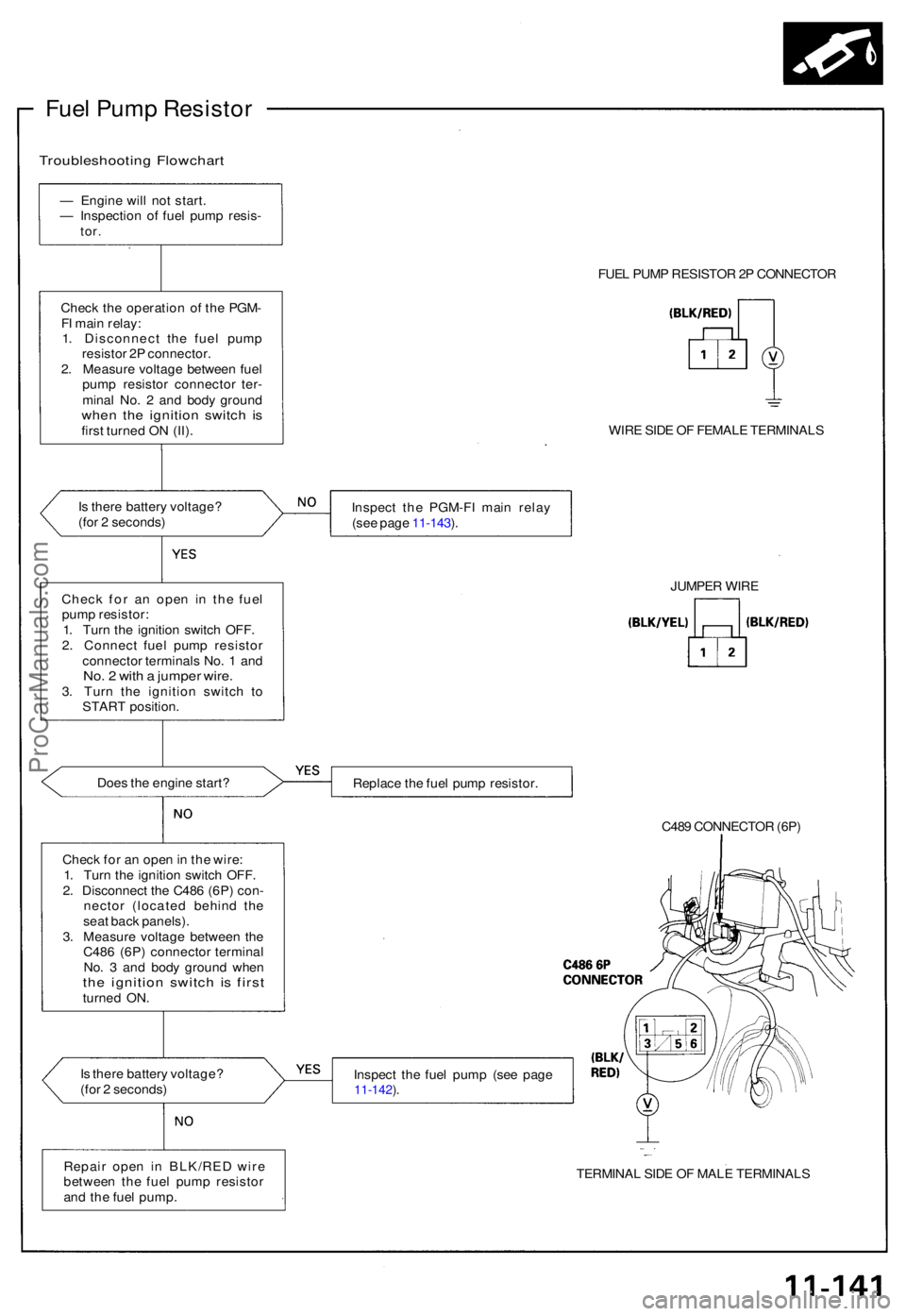
Fuel Pum p Resisto r
Troubleshootin g Flowchar t
— Engin e wil l no t start .
— Inspectio n o f fue l pum p resis -
tor.
Chec k th e operatio n o f th e PGM -
F I mai n relay :
1 . Disconnec t th e fue l pum p
resisto r 2 P connector .
2 . Measur e voltag e betwee n fue l
pum p resisto r connecto r ter -
mina l No . 2 an d bod y groun d
when th e ignitio n switc h i sfirs t turne d O N (II) .
I s ther e batter y voltage ?
(fo r 2 seconds )
Doe s th e engin e start ?
Chec k fo r a n ope n in th e wire :
1 . Tur n th e ignitio n switc h OFF .
2 . Disconnec t th e C48 6 (6P ) con -
necto r (locate d behin d th e
sea t bac k panels) .
3 . Measur e voltag e betwee n th e
C48 6 (6P ) connecto r termina l
No . 3 an d bod y groun d whe n
the ignitio n switc h i s firs tturne d ON .
I s ther e batter y voltage ?
(fo r 2 seconds ) FUE
L PUM P RESISTO R 2P CONNECTO R
WIR E SID E O F FEMAL E TERMINAL S
Inspec t th e PGM-F I mai n rela y
(se e pag e 11-143 ).
Replac e th e fue l pum p resistor .
C489 CONNECTO R (6P )
Inspec t th e fue l pum p (se e pag e
11-142 ).
TERMINA L SID E O F MAL E TERMINAL S
JUMPE
R WIR E
Chec k fo r a n ope n i n th e fue l
pum p resistor :
1 . Tur n th e ignitio n switc h OFF .
2 . Connec t fue l pum p resisto r
connecto r terminal s No . 1 an d
No. 2 wit h a jumpe r wire .3. Tur n th e ignitio n switc h t o
STAR T position .
Repai r ope n i n BLK/RE D wir e
betwee n th e fue l pum p resisto r
an d th e fue l pump .
ProCarManuals.com
Page 304 of 1640
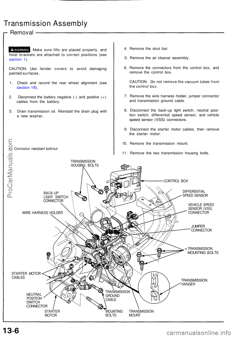
Transmission Assembl y
Removal
Make sur e lift s ar e place d properly , an d
hois t bracket s ar e attache d t o correc t position s (se e
sectio n 1 ).
CAUTION : Us e fende r cover s t o avoi d damagin g
painte d surfaces .
1 . Chec k an d recor d th e rea r whee l alignmen t (se e
sectio n 18 ).
2 . Disconnec t th e batter y negativ e (- ) an d positiv e (+ )
cable s fro m th e battery .
3 . Drai n transmissio n oil . Reinstal l th e drai n plu g wit h
a ne w washer .
Corrosio n resistan t bolt/nu t
4. Remov e th e stru t bar .
5 . Remov e th e ai r cleane r assembly .
6 . Remov e th e connector s fro m th e contro l box , an d
remov e th e contro l box .
CAUTION : D o no t remov e th e vacuu m tube s fro m
th e contro l box .
7 . Remov e th e wir e harnes s holder , jumpe r connecto r
an d transmissio n ground cable.
8 . Disconnec t th e back-u p ligh t switch , neutra l posi -
tio n switch , differentia l spee d sensor , an d vehicl e
speed senso r (VSS ) connectors .
9. Disconnec t th e starte r moto r cables , the n remov e
th e starte r motor .
10 . Remov e th e transmissio n mount .
11 . Remov e th e tw o transmissio n housin g bolts .
TRANSMISSIO N
HOUSIN G BOLT S
CONTROL BO X
BACK-U PLIGHT SWITC H
CONNECTO R
WIR E HARNES S HOLDE R
STARTER MOTOR
CABLES
NEUTRA L
POSITIO N
SWITCHCONNECTO R
DIFFERENTIA L
SPEE D SENSO R
VEHICL E SPEE D
SENSO R (VSS )
CONNECTO R
JUMPERCONNECTO R
TRANSMISSIO N
MOUNTING BOLT S
TRANSMISSIO NHANGER
STARTE RMOTOR MOUNTIN
G TRANSMISSIO N
BOLT S MOUN T
TRANSMISSIO
N
GROUN D
CABLE
ProCarManuals.com
Page 355 of 1640
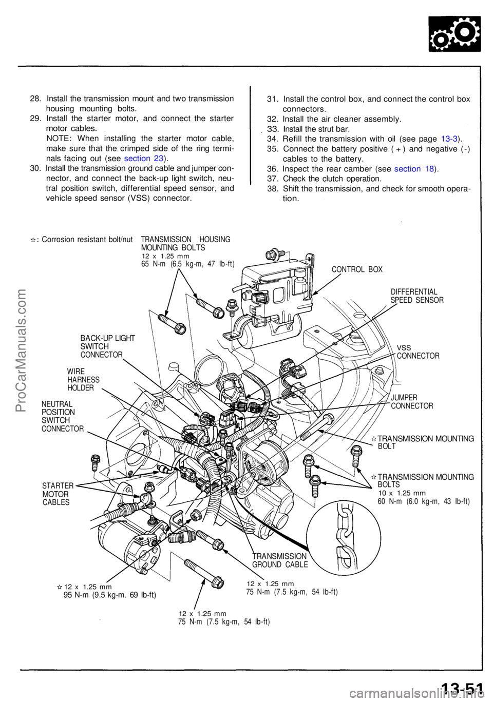
28. Instal l th e transmissio n moun t an d tw o transmissio n
housin g mountin g bolts .
29 . Instal l th e starte r motor , an d connec t th e starte r
motor cables .
NOTE: Whe n installin g th e starte r moto r cable ,
mak e sur e tha t th e crimpe d sid e o f th e rin g termi -
nal s facin g ou t (se e sectio n 23 ).
30 . Instal l th e transmissio n groun d cabl e an d jumpe r con -
nector , an d connec t th e back-u p ligh t switch , neu -
tra l positio n switch , differentia l spee d sensor , an d
vehicl e spee d senso r (VSS ) connector . 31
. Instal l th e contro l box , an d connec t th e contro l bo x
connectors .
32. Instal l th e ai r cleane r assembly .
33. Instal l th e stru t bar .
34 . Refil l th e transmissio n wit h oi l (se e pag e 13-3 ).
35 . Connec t th e batter y positiv e ( + ) an d negativ e (- )
cable s t o th e battery .
36 . Inspec t th e rea r cambe r (se e sectio n 18 ).
37 . Chec k th e clutc h operation .
38 . Shif t th e transmission , an d chec k fo r smoot h opera -
tion.
Corrosio n resistan t bolt/nu tTRANSMISSIO N HOUSIN GMOUNTING BOLT S12 x 1.2 5 mm65 N- m (6. 5 kg-m , 4 7 Ib-ft )
CONTROL BO X
BACK-U P LIGH TSWITC HCONNECTO R
WIR E
HARNES S
HOLDE R
NEUTRA L
POSITIONSWITCHCONNECTO R
STARTE R
MOTORCABLE S DIFFERENTIA
L
SPEE D SENSO R
VSSCONNECTO R
JUMPE R
CONNECTO R
TRANSMISSIO N MOUNTIN GBOLT
TRANSMISSIO N MOUNTIN GBOLTS10 x 1.2 5 mm60 N- m (6. 0 kg-m , 4 3 Ib-ft )
12 x 1.2 5 mm95 N- m (9. 5 kg-m . 6 9 Ib-ft )
12 x 1.2 5 mm75 N- m (7. 5 kg-m , 5 4 Ib-ft )
12 x 1.2 5 mm75 N- m (7. 5 kg-m , 5 4 Ib-ft )
TRANSMISSIO NGROUND CABL E
ProCarManuals.com
Page 530 of 1640
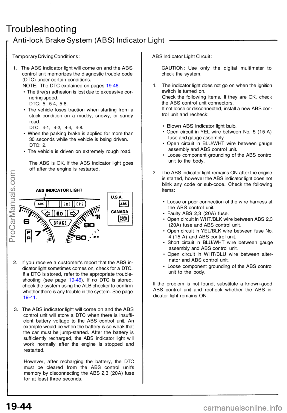
Troubleshooting
Anti-lock Brak e Syste m (ABS ) Indicato r Ligh t
Temporar y Drivin g Conditions :
1. Th e AB S indicato r ligh t wil l com e o n an d th e AB S
contro l uni t memorize s th e diagnosti c troubl e cod e
(DTC ) unde r certai n conditions .
NOTE : Th e DT C explaine d o n page s 19-46 .
• Th e tire(s ) adhesio n is los t du e to excessiv e cor -
nerin g speed .
DTC: 5, 5-4 , 5-8 .
• Th e vehicl e lose s tractio n whe n startin g fro m a
stuc k conditio n o n a muddy , snowy , o r sand y
road.
DTC: 4-1 , 4-2 , 4-4 , 4-8 .
• Whe n th e parkin g brak e is applie d fo r mor e tha n
3 0 second s whil e th e vehicl e i s bein g driven .
DTC: 2.
• Th e vehicl e is drive n o n extremel y roug h road .
Th e AB S is OK , i f th e AB S indicato r ligh t goe s
of f afte r th e engin e i s restarted .
2 . I f yo u receiv e a customer' s repor t tha t th e AB S in -
dicato r ligh t sometime s come s on , chec k fo r a DTC .
I f a DT C is stored , refe r t o th e appropriat e trouble -
shootin g (se e pag e 19-46 ). I f n o DT C is stored ,
chec k th e syste m usin g th e AL B checke r t o confir m
whethe r ther e is an y troubl e in th e system . Se e pag e
19-41 .
3. Th e AB S indicato r ligh t wil l com e o n an d th e AB S
contro l uni t wil l stor e a DT C whe n ther e i s insuffi -
cien t batter y voltag e t o th e AB S contro l unit . A n
exampl e woul d b e whe n th e batter y is s o wea k tha t
th e ca r mus t b e jump-started . Afte r th e batter y i s
sufficientl y recharged , th e AB S indicato r ligh t wil l
wor k normall y afte r th e engin e i s stoppe d an d
restarted .
However , afte r rechargin g th e battery , th e DT C
mus t b e cleare d fro m th e AB S contro l unit' s
memor y b y disconnectin g th e AB S 2, 3 (20A ) fus e
fo r a t leas t thre e seconds . AB
S Indicato r Ligh t Circuit :
CAUTION : Us e onl y th e digita l multimete r t o
chec k th e system .
1. Th e indicato r ligh t doe s no t g o o n whe n th e ignitio n
switc h i s turne d on .
Chec k th e followin g items . I f the y ar e OK , chec k
th e AB S contro l uni t connectors .
I f no t loos e o r disconnected , instal l a ne w AB S con -
tro l uni t an d recheck :
• Blow n AB S indicato r ligh t bulb .
• Ope n circui t i n YE L wir e betwee n No . 5 (1 5 A )
fus e an d gaug e assembly .
• Ope n circui t i n BLU/WH T wir e betwee n gaug e
assembl y an d AB S contro l unit .
• Loos e componen t groundin g of the AB S contro l
uni t t o th e body .
2 . Th e AB S indicato r ligh t remain s O N afte r th e engin e
i s started , howeve r th e AB S indicato r ligh t doe s no t
blin k an y cod e o r sub-code . Chec k th e followin g
items :
• Loos e o r poo r connectio n of the wir e harnes s a t
th e AB S contro l unit .
• Fault y AB S 2, 3 (20A ) fuse .
• Ope n circui t i n WHT/BL K wir e betwee n AB S 2, 3
(20A ) fus e an d AB S contro l unit .
• Ope n circui t i n YEL/BL K wir e betwee n fus e No .
4 (1 5 A ) an d AB S contro l unit .
• Shor t circui t i n BLU/WH T wir e betwee n gaug e
assembl y an d AB S contro l unit .
• Ope n circui t i n WHT/BL U wir e betwee n alter -
nato r an d AB S contro l unit .
• Loos e componen t groundin g o f th e AB S contro l
uni t t o th e body .
I f th e proble m is no t found , substitut e a known-goo d
AB S contro l uni t an d rechec k whethe r th e AB S in -
dicato r ligh t remain s ON .
ProCarManuals.com
Page 531 of 1640
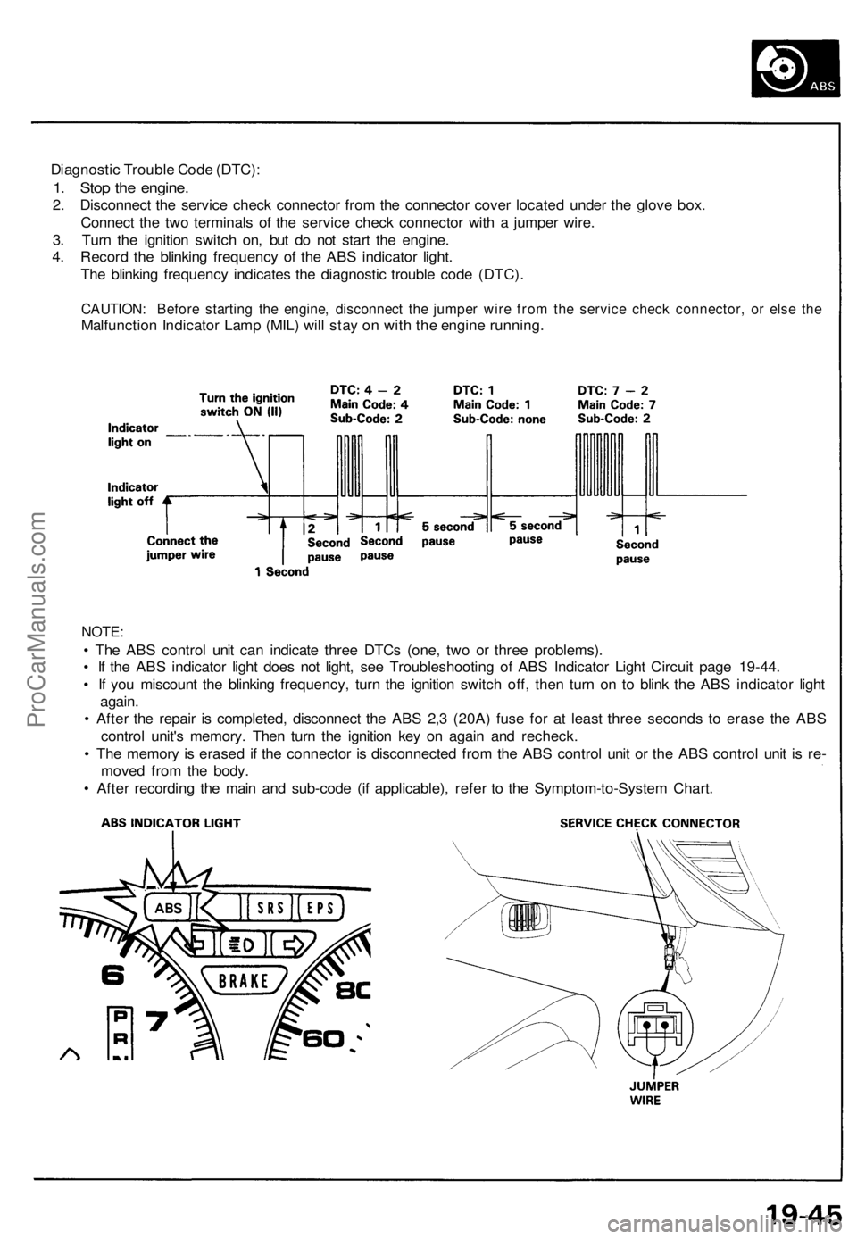
Diagnostic Trouble Code (DTC):
1. Stop the engine.
2. Disconnect the service check connector from the connector cover located under the glove box.
Connect the two terminals of the service check connector with a jumper wire.
3. Turn the ignition switch on, but do not start the engine.
4. Record the blinking frequency of the ABS indicator light.
The blinking frequency indicates the diagnostic trouble code (DTC).
CAUTION: Before starting the engine, disconnect the jumper wire from the service check connector, or else the
Malfunction Indicator Lamp (MIL) will stay on with the engine running.
NOTE:
• The ABS control unit can indicate three DTCs (one, two or three problems).
• If the ABS indicator light does not light, see Troubleshooting of ABS Indicator Light Circuit page 19-44.
• If you miscount the blinking frequency, turn the ignition switch off, then turn on to blink the ABS indicator light
again.
• After the repair is completed, disconnect the ABS 2,3 (20A) fuse for at least three seconds to erase the ABS
control unit's memory. Then turn the ignition key on again and recheck.
• The memory is erased if the connector is disconnected from the ABS control unit or the ABS control unit is re-
moved from the body.
• After recording the main and sub-code (if applicable), refer to the Symptom-to-System Chart.ProCarManuals.com
Page 537 of 1640
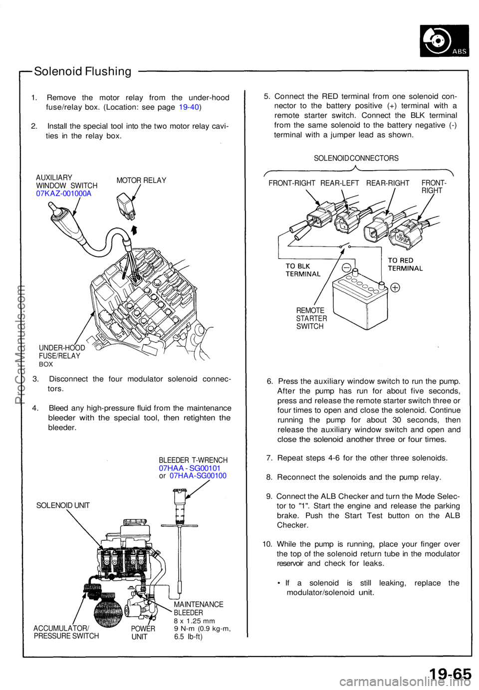
Solenoid Flushin g
1. Remov e th e moto r rela y fro m th e under-hoo d
fuse/rela y box . (Location : se e pag e 19-40 )
2 . Instal l th e specia l too l int o th e tw o moto r rela y cavi -
tie s i n th e rela y box .
AUXILIAR Y
WINDO W SWITC H
07KAZ-001000 A
MOTOR RELA Y
UNDER-HOO DFUSE/RELAYBOX
3. Disconnec t th e fou r modulato r solenoi d connec -
tors .
4 . Blee d an y high-pressur e flui d fro m th e maintenanc e
bleeder wit h th e specia l tool , the n retighte n th e
bleeder .
SOLENOI D UNI T
BLEEDE R T-WRENC H07HAA - SG0010 1or 07HA A-SG0010 0
ACCUMULATOR /
PRESSUR E SWITC HPOWERUNIT
MAINTENANC EBLEEDER8 x 1.2 5 mm9 N- m (0. 9 kg-m ,6.5 Ib-ft )
5. Connec t th e RE D termina l fro m on e solenoi d con -
necto r t o th e batter y positiv e (+ ) termina l wit h a
remot e starte r switch . Connec t th e BL K termina l
fro m th e sam e solenoi d t o th e batter y negativ e (- )
termina l wit h a jumpe r lea d a s shown .
SOLENOI D CONNECTOR S
FRONT-RIGH T REAR-LEF T REAR-RIGH T
FRONT-RIGHT
REMOT ESTARTE RSWITCH
6. Pres s th e auxiliar y windo w switc h t o ru n th e pump .
Afte r th e pum p ha s ru n fo r abou t fiv e seconds ,
pres s an d releas e th e remot e starte r switc h thre e o r
fou r time s t o ope n an d clos e th e solenoid . Continu e
runnin g th e pum p fo r abou t 3 0 seconds , the n
releas e th e auxiliar y windo w switc h an d ope n an d
clos e th e solenoi d anothe r thre e o r fou r times .
7. Repea t step s 4- 6 fo r th e othe r thre e solenoids .
8 . Reconnec t th e solenoid s an d th e pum p relay .
9 . Connec t th e AL B Checke r an d tur n th e Mod e Selec -
to r t o "1" . Star t th e engin e an d releas e th e parkin g
brake . Pus h th e Star t Tes t butto n o n th e AL B
Checker .
10. Whil e th e pum p i s running , plac e you r finge r ove r
th e to p o f th e solenoi d retur n tub e in th e modulato r
reservoi r an d chec k fo r leaks .
• I f a solenoi d i s stil l leaking , replac e th e
modulator/solenoi d
unit.
ProCarManuals.com
Page 748 of 1640
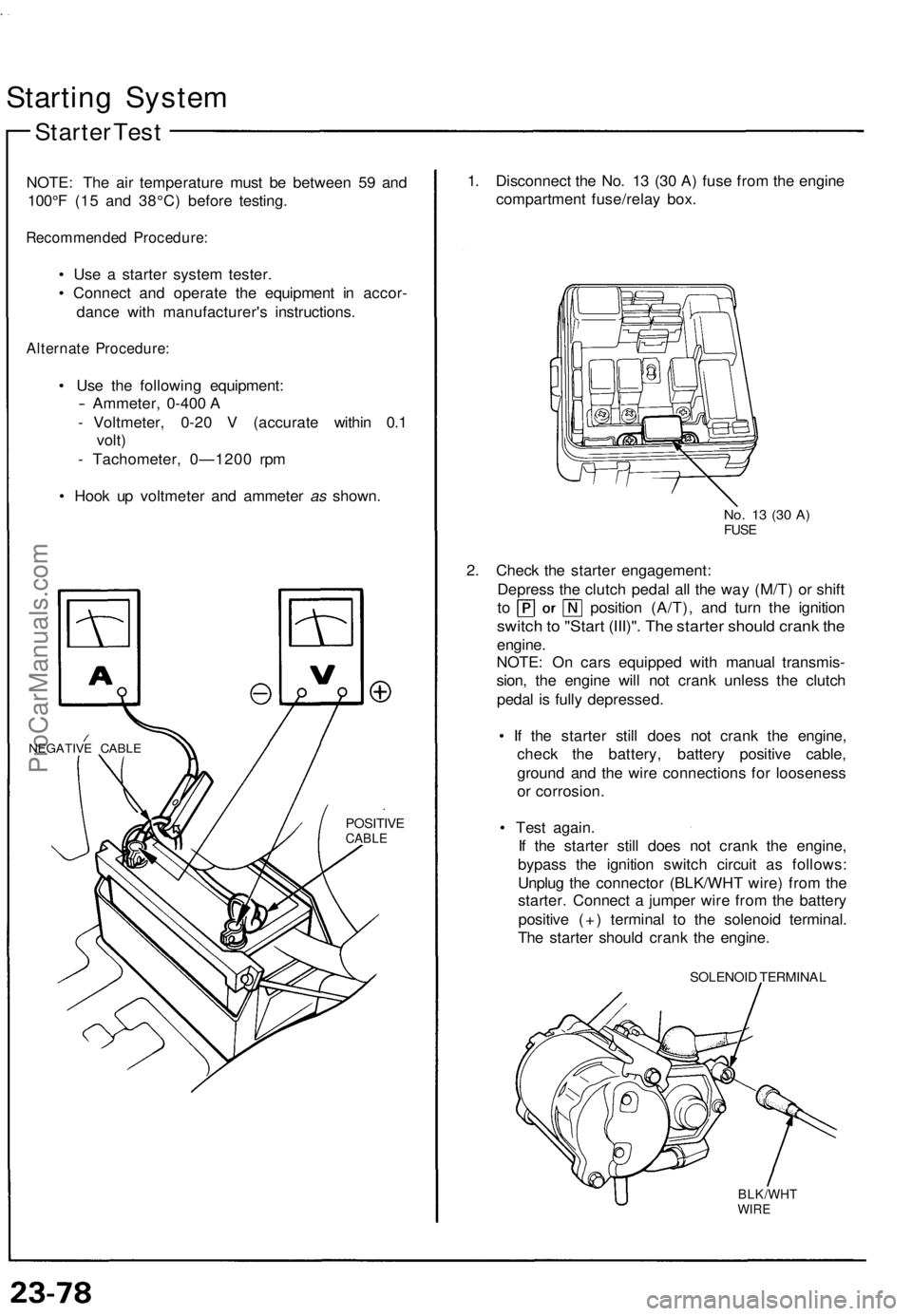
Starting Syste m
Starter Tes t
NOTE : Th e ai r temperatur e mus t b e betwee n 5 9 an d
100° F (1 5 an d 38°C ) befor e testing .
Recommende d Procedure :
• Us e a starte r syste m tester .
• Connec t an d operat e th e equipmen t i n accor -
danc e wit h manufacturer' s instructions .
Alternate Procedure :
• Us e th e followin g equipment :
- Ammeter, 0-400 A
- Voltmeter , 0-2 0 V (accurat e withi n 0. 1
volt )
- Tachometer , 0—120 0 rp m
• Hoo k u p voltmete r an d ammete r as shown .
NEGATIV E CABL E
POSITIV ECABLE
1. Disconnec t th e No . 1 3 (3 0 A ) fus e fro m th e engin e
compartmen t fuse/rela y box .
No. 1 3 (3 0 A )FUS E
2. Chec k th e starte r engagement :
Depres s th e clutc h peda l al l th e wa y (M/T ) o r shif t
to positio n (A/T) , an d tur n th e ignitio n
switch to "Star t (III)" . Th e starte r shoul d cran k th e
engine .
NOTE : O n car s equippe d wit h manua l transmis -
sion , th e engin e wil l no t cran k unles s th e clutc h
peda l i s full y depressed .
• I f th e starte r stil l doe s no t cran k th e engine ,
chec k th e battery , batter y positiv e cable ,
groun d an d th e wir e connection s fo r loosenes s
o r corrosion .
• Tes t again .
I f th e starte r stil l doe s no t cran k th e engine ,
bypas s th e ignitio n switc h circui t a s follows :
Unplu g th e connecto r (BLK/WH T wire ) fro m th e
starter . Connec t a jumpe r wir e fro m th e batter y
positiv e (+ ) termina l t o th e solenoi d terminal .
Th e starte r shoul d cran k th e engine .
SOLENOI D TERMINA L
BLK/WHTWIRE
ProCarManuals.com