Page 1554 of 1640

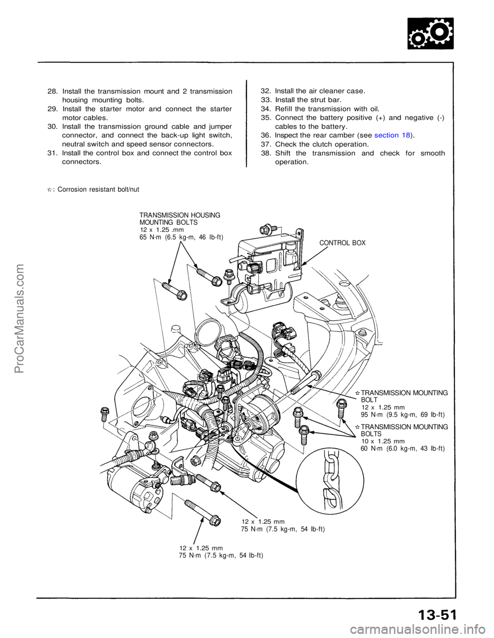
28. Install the transmission mount and 2 transmission
housing mounting bolts.
29. Install the starter motor and connect the starter motor cables.
30. Install the transmission ground cable and jumper connector, and connect the back-up light switch,
neutral switch and speed sensor connectors.
31. Install the control box and connect the control box
connectors.
Corrosion resistant bolt/nut
TRANSMISSION HOUSING
MOUNTING BOLTS
12 x
1.25
.mm
65 N·m (6.5 kg-m, 46 Ib-ft)
12 x
1.25
mm
75 N·m (7.5 kg-m, 54 Ib-ft)
12 x
1.25
mm
75 N·m (7.5 kg-m, 54 Ib-ft)
TRANSMISSION MOUNTING
BOLTS
10 x
1.25
mm
60 N·m (6.0 kg-m, 43 Ib-ft)
TRANSMISSION MOUNTING
BOLT
12 x
1.25
mm
95 N·m (9.5 kg-m, 69 Ib-ft)
CONTROL BOX
32. Install the air cleaner case.
33. Install the strut bar.
34. Refill the transmission with oil.
35. Connect the battery positive (+) and negative (-) cables to the battery.
36. Inspect the rear camber (see section 18).
37. Check the clutch operation.
38. Shift the transmission and check for smooth
operation.ProCarManuals.com
Page 1569 of 1640

Troubleshooting
Anti-lock Brake System Indicator Light
Temporary Driving Conditions:
1. The anti-lock brake system indicator light will come
on and the control unit memorizes the problem
under certain conditions.
NOTE: Problem codes are explained on pages
19 - 46.
The tire(s) adhesion is lost due to excessive cor-
nering speed.
Problem codes: 5, 5-4, 5-8. The vehicle loses traction when starting from a
stuck condition on a muddy, snowy, or sandy
road.
Problem code: 4-1, 4-2, 4-4, 4-8. When the parking brake is applied for more than
30 seconds while the vehicle is being driven.
Problem code: 2. The vehicle is driven on extremely rough road.
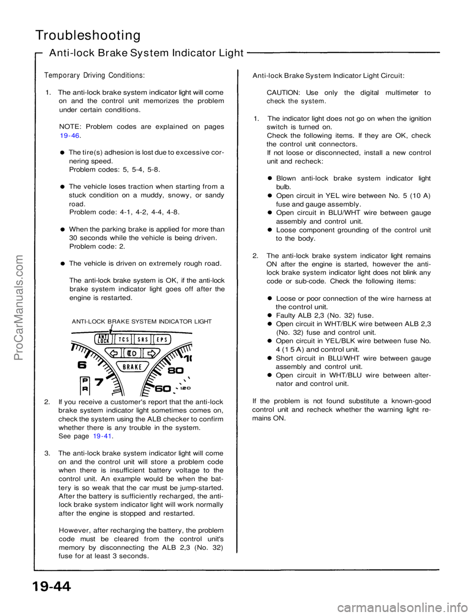
The anti-lock brake system is OK, if the anti-lock brake system indicator light goes off after the
engine is restarted.
ANTI-LOCK BRAKE SYSTEM INDICATOR LIGHT
2. If you receive a customer's report that the anti-lock brake system indicator light sometimes comes on,
check the system using the ALB checker to confirm
whether there is any trouble in the system.
See page 19 - 41.
3. The anti-lock brake system indicator light will come on and the control unit will store a problem codewhen there is insufficient battery voltage to the
control unit. An example would be when the bat-
tery is so weak that the car must be jump-started. After the battery is sufficiently recharged, the anti-lock brake system indicator light will work normally
after the engine is stopped and restarted.
However, after recharging the battery, the problem
code must be cleared from the control unit's
memory by disconnecting the ALB 2,3 (No. 32)
fuse for at least 3 seconds. Anti-lock Brake System Indicator Light Circuit:
CAUTION: Use only the digital multimeter to
check the system.
1. The indicator light does not go on when the ignition switch is turned on.
Check the following items. If they are OK, check
the control unit connectors. If not loose or disconnected, install a new control
unit and recheck:
Blown anti-lock brake system indicator light
bulb.
Open circuit in YEL wire between No. 5 (10 A)
fuse and gauge assembly. Open circuit in BLU/WHT wire between gauge
assembly and control unit. Loose component grounding of the control unit
to the body.
2. The anti-lock brake system indicator light remains ON after the engine is started, however the anti-lock brake system indicator light does not blink any
code or sub-code. Check the following items:
Loose or poor connection of the wire harness at
the control unit.
Faulty ALB 2,3 (No. 32) fuse.
Open circuit in WHT/BLK wire between ALB 2,3(No. 32) fuse and control unit.
Open circuit in YEL/BLK wire between fuse No.
4 (1 5 A) and control unit.
Short circuit in BLU/WHT wire between gauge
assembly and control unit. Open circuit in WHT/BLU wire between alter-
nator and control unit.
If the problem is not found substitute a known-good
control unit and recheck whether the warning light re-
mains ON.ProCarManuals.com
Page 1570 of 1640

Comes on and remains on while running:
1. Stop the engine.
2. Turn the ignition switch on and make sure that the anti-lock brake system indicator light comes on.
3. Restart the engine and check the anti-lock brake system indicator light.
There is no problem in the anti-lock brake system, if the anti-lock brake system indicator light goes off. Go to step 4, if the anti-lock brake system indicator light remains on.
4. Stop the engine.
5. Disconnect the service check connector from the connector cover located under the glove box.
Connect the two terminals of the service check connector with a jumper wire.
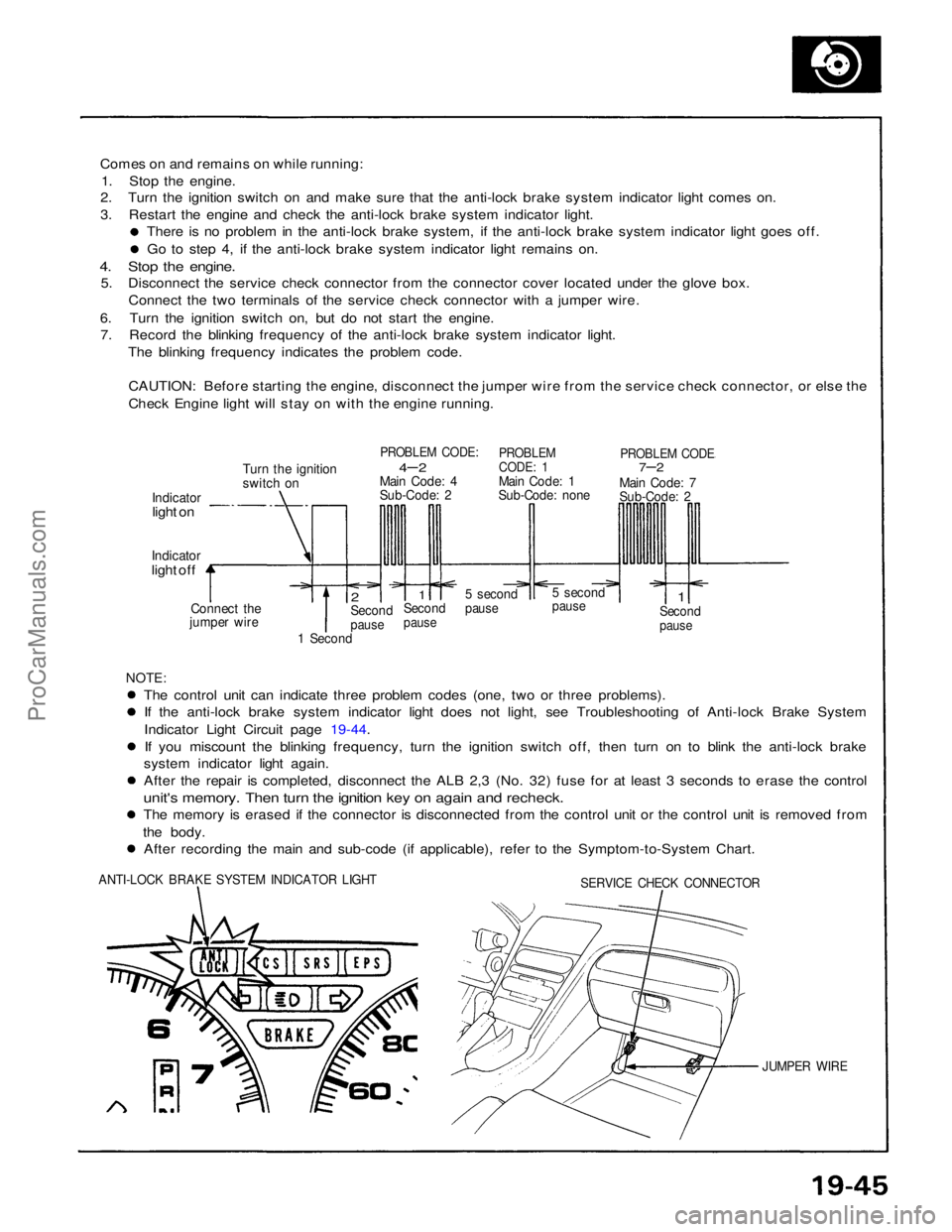
6. Turn the ignition switch on, but do not start the engine. 7. Record the blinking frequency of the anti-lock brake system indicator light.
The blinking frequency indicates the problem code.
CAUTION: Before starting the engine, disconnect the jumper wire from the service check connector, or else the
Check Engine light will stay on with the engine running.
Turn the ignition
switch on
PROBLEM CODE:
4– 2
Main Code: 4
Sub-Code: 2
PROBLEM
CODE: 1
Main Code: 1
Sub-Code: none
PROBLEM CODE
7–2
Main Code: 7
Sub-Code: 2
Indicator
light on
Indicator
light off
Connect the
jumper wire
2
Second
pause
1
Second
pause
5 second
pause
5 second
pause
1
Second
pause
1 Second
NOTE:
The control unit can indicate three problem codes (one, two or three problems). If the anti-lock brake system indicator light does not light, see Troubleshooting of Anti-lock Brake System
Indicator Light Circuit page 19-44.
If you miscount the blinking frequency, turn the ignition switch off, then turn on to blink the anti-lock brake
system indicator light again. After the repair is completed, disconnect the ALB 2,3 (No. 32) fuse for at least 3 seconds to erase the control
unit's memory. Then turn the ignition key on again and recheck.
The memory is erased if the connector is disconnected from the control unit or the control unit is removed from
the body. After recording the main and sub-code (if applicable), refer to the Symptom-to-System Chart.
ANTI-LOCK BRAKE SYSTEM INDICATOR LIGHT
SERVICE CHECK CONNECTOR
JUMPER WIREProCarManuals.com
Page 1575 of 1640

Solenoid Flushing
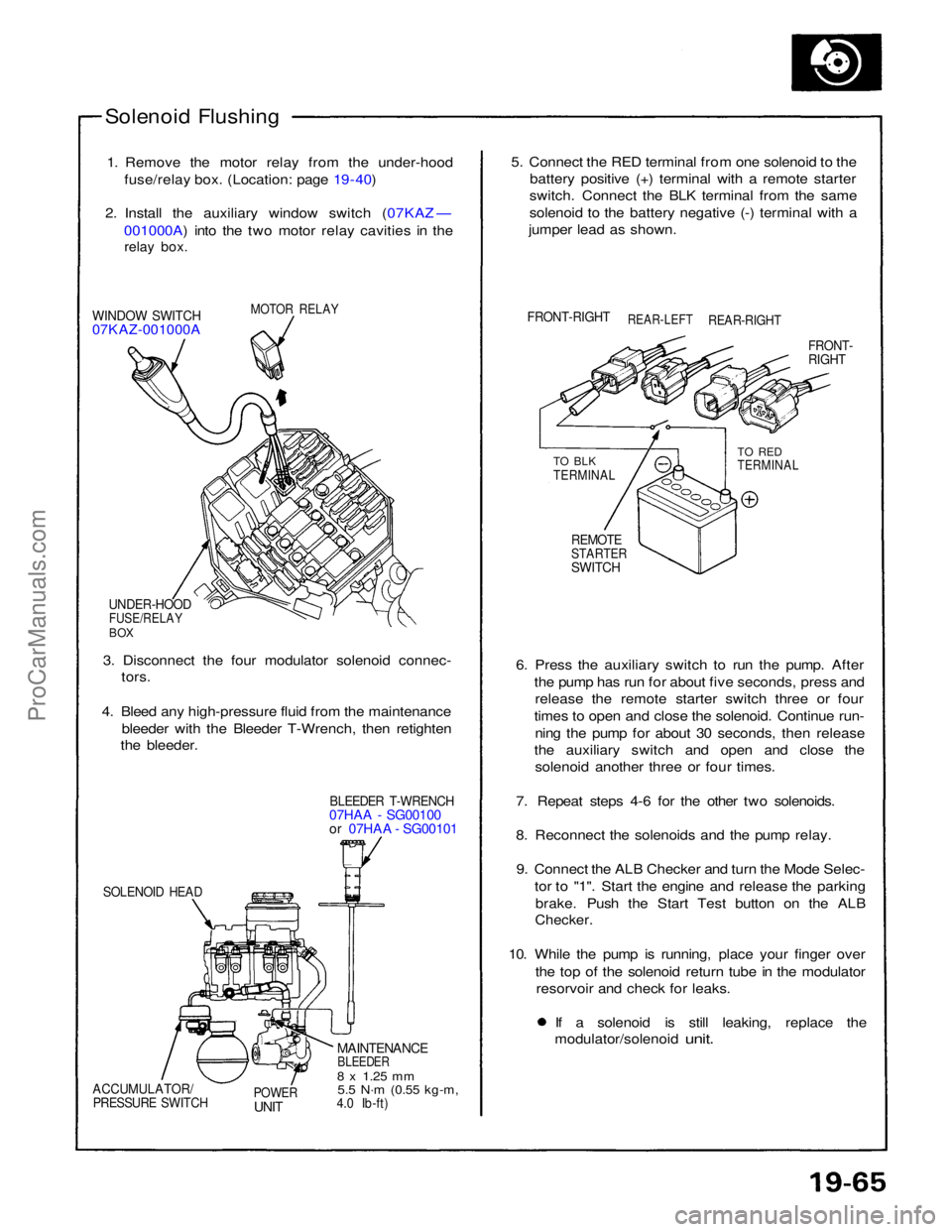
1. Remove the motor relay from the under-hood fuse/relay box. (Location: page 19 - 40)
2. Install the auxiliary window switch (07KAZ — 001000A) into the two motor relay cavities in the
relay box.
MOTOR RELAY
WINDOW SWITCH
07KAZ-001000A
UNDER-HOOD
FUSE/RELAY
BOX
3. Disconnect the four modulator solenoid connec- tors.
4. Bleed any high-pressure fluid from the maintenance bleeder with the Bleeder T-Wrench, then retighten
the bleeder.
BLEEDER T-WRENCH
07HAA - SG00100
or 07HAA - SG00101
SOLENOID HEAD
MAINTENANCE
BLEEDER
8 x
1.25
mm
5.5 N·m
(0.55 kg-m,
4.0 Ib-ft)
POWER
UNIT
ACCUMULATOR/
PRESSURE SWITCH
6. Press the auxiliary switch to run the pump. After
the pump has run for about five seconds, press andrelease the remote starter switch three or four
times to open and close the solenoid. Continue run- ning the pump for about 30 seconds, then release
the auxiliary switch and open and close the solenoid another three or four times.
7. Repeat steps 4-6 for the other two solenoids.
8. Reconnect the solenoids and the pump relay. 9. Connect the ALB Checker and turn the Mode Selec- tor to "1". Start the engine and release the parkingbrake. Push the Start Test button on the ALB
Checker.
10. While the pump is running, place your finger over the top of the solenoid return tube in the modulatorresorvoir and check for leaks. If a solenoid is still leaking, replace the
modulator/solenoid
unit.
REMOTE
STARTER
SWITCH
TO BLK
TERMINAL
TO RED
TERMINAL
FRONT-
RIGHT
FRONT-RIGHT
REAR-LEFT
REAR-RIGHT
5. Connect the RED terminal from one solenoid to the
battery positive (+) terminal with a remote starter
switch. Connect the BLK terminal from the same
solenoid to the battery negative (-) terminal with a
jumper lead as shown.ProCarManuals.com