Page 6 of 1640
![ACURA NSX 1991 Service Repair Manual
Warning/Caution Label Locations
A: CABLE REEL CAUTION
[SRS]
REFER TO SERVICE MANUAL FOR DETAILED IN-
STRUCTIONS.
B: STEERING WHEEL NOTICE
NOTICE
IMPROPER STEERING WHEEL REMOVAL OR IN-
STALLAT](/manual-img/32/56988/w960_56988-5.png "ACURA NSX 1991 Service Repair Manual
Warning/Caution Label Locations
A: CABLE REEL CAUTION
[SRS]
REFER TO SERVICE MANUAL FOR DETAILED IN-
STRUCTIONS.
B: STEERING WHEEL NOTICE
NOTICE
IMPROPER STEERING WHEEL REMOVAL OR IN-
STALLAT")
Warning/Caution Label Locations
A: CABLE REEL CAUTION
[SRS]
REFER TO SERVICE MANUAL FOR DETAILED IN-
STRUCTIONS.
B: STEERING WHEEL NOTICE
NOTICE
IMPROPER STEERING WHEEL REMOVAL OR IN-
STALLATION CAN DAMAGE SRS COMPONENTS.
FOLLOW SERVICE MANUAL INSTRUCTIONS
CAREFULLY.
C: DRIVER MODULE WARNING
A WARNING
THE AIRBAG INFLATOR IS EXPLOSIVE AND. IF AC-
CIDENTALLY DEPLOYED. CAN SERIOUSLY HURT OR
KILL YOU.
• DO NOT USE ELECTRICAL TEST EQUIPMENT OR
PROBING DEVICES.
THEY CAN CAUSE ACCIDENTAL DEPLOYMENT.
• NO SERVICEABLE PARTS INSIDE. DO NOT DISAS-
SEMBLE.
• PLACE AIRBAG UPRIGHT WHEN REMOVED.
• FOLLOW SERVICE MANUAL INSTRUCTIONS
CAREFULLY.
D: DRIVER'S INFLATOR CAUTION
A DANGER
EXPLOSIVE/FLAMMABLE
CONTACT WITH ACID, WATER OR HEAVY METALS
SUCH AS COPPER, LEAD OR MERCURY MAY PRODUCE
HARMFUL AND IRRITATING GASES OR EXPLOSIVE
COMPOUNDS. STORAGE TEMPERATURES MUST NOT
EXCEED 200°F (100°C). FOR PROPER HANDLING,
STORAGE AND DISPOSAL PROCEDURES REFER TO
SERVICE MANUAL, SRS SUPPLEMENT.
POISON
CONTAINS POISONOUS SODIUM AZIDE AND POTAS-
SIUM NITRATE.
FIRST AID
IF CONTENTS ARE SWALLOWED, INDUCE VOMITING.
FOR EYE CONTACT, FLUSH EYES WITH WATER FOR 15
MINUTES. IF GASES (FROM ACID OR WATER CON-
TACT) ARE INHALED, SEEK FRESH AIR. IN EVERY CASE,
GET PROMPT MEDICAL ATTENTION.
KEEP OUT OF REACH OF CHILDREN.ProCarManuals.com
Page 39 of 1640
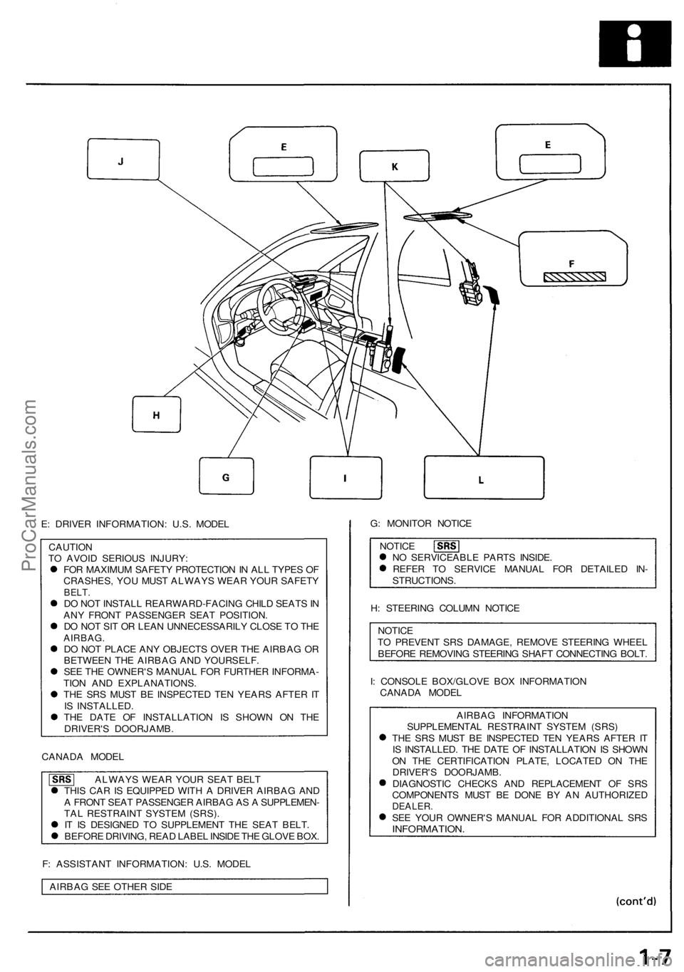
E: DRIVER INFORMATION: U.S. MODEL
CAUTION
TO AVOID SERIOUS INJURY:
FOR MAXIMUM SAFETY PROTECTION IN ALL TYPES OF
CRASHES, YOU MUST ALWAYS WEAR YOUR SAFETY
BELT.
DO NOT INSTALL REARWARD-FACING CHILD SEATS IN
ANY FRONT PASSENGER SEAT POSITION.
DO NOT SIT OR LEAN UNNECESSARILY CLOSE TO THE
AIRBAG.
DO NOT PLACE ANY OBJECTS OVER THE AIRBAG OR
BETWEEN THE AIRBAG AND YOURSELF.
SEE THE OWNER'S MANUAL FOR FURTHER INFORMA-
TION AND EXPLANATIONS.
THE SRS MUST BE INSPECTED TEN YEARS AFTER IT
IS INSTALLED.
THE DATE OF INSTALLATION IS SHOWN ON THE
DRIVER'S DOORJAMB.
CANADA MODEL
ALWAYS WEAR YOUR SEAT BELT
THIS CAR IS EQUIPPED WITH A DRIVER AIRBAG AND
A FRONT SEAT PASSENGER AIRBAG AS A SUPPLEMEN-
TAL RESTRAINT SYSTEM (SRS).
IT IS DESIGNED TO SUPPLEMENT THE SEAT BELT.
BEFORE DRIVING, READ LABEL INSIDE THE GLOVE BOX.
F: ASSISTANT INFORMATION: U.S. MODEL
AIRBAG SEE OTHER SIDE
G: MONITOR NOTICE
NOTICE
NO SERVICEABLE PARTS INSIDE.
REFER TO SERVICE MANUAL FOR DETAILED IN-
STRUCTIONS.
H: STEERING COLUMN NOTICE
NOTICE
TO PREVENT SRS DAMAGE, REMOVE STEERING WHEEL
BEFORE REMOVING STEERING SHAFT CONNECTING BOLT.
I: CONSOLE BOX/GLOVE BOX INFORMATION
CANADA MODEL
AIRBAG INFORMATION
SUPPLEMENTAL RESTRAINT SYSTEM (SRS)
THE SRS MUST BE INSPECTED TEN YEARS AFTER IT
IS INSTALLED. THE DATE OF INSTALLATION IS SHOWN
ON THE CERTIFICATION PLATE, LOCATED ON THE
DRIVER'S DOORJAMB.
DIAGNOSTIC CHECKS AND REPLACEMENT OF SRS
COMPONENTS MUST BE DONE BY AN AUTHORIZED
DEALER.
SEE YOUR OWNER'S MANUAL FOR ADDITIONAL SRS
INFORMATION.ProCarManuals.com
Page 404 of 1640
System Description
Steering Column
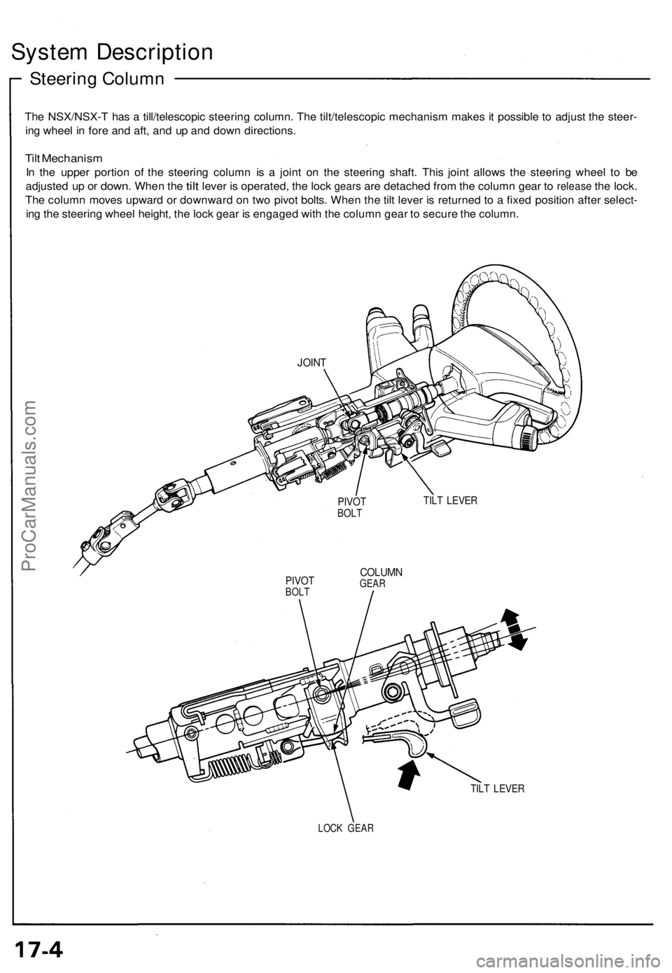
The NSX/NSX-T has a till/telescopic steering column. The tilt/telescopic mechanism makes it possible to adjust the steer-
ing wheel in fore and aft, and up and down directions.
Tilt Mechanism
In the upper portion of the steering column is a joint on the steering shaft. This joint allows the steering wheel to be
adjusted
up or
down.
When
the
tilt
lever
is
operated,
the
lock
gears
are
detached from
the
column gear
to
release
the
lock.
The column moves upward or downward on two pivot bolts. When the tilt lever is returned to a fixed position after select-
ing the steering wheel height, the lock gear is engaged with the column gear to secure the column.
TILT LEVER
PIVOT
BOLT
COLUMN
GEAR
TILT LEVER
LOCK GEAR
JOINT
PIVOT
BOLTProCarManuals.com
Page 405 of 1640
Telescopic Mechanism
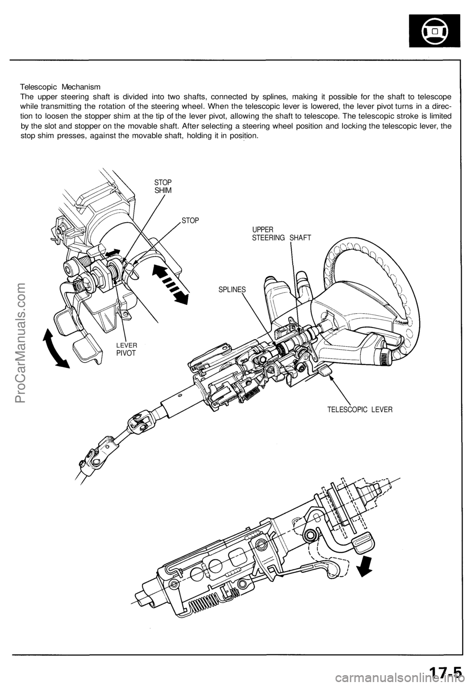
The upper steering shaft is divided into two shafts, connected by splines, making it possible for the shaft to telescope
while transmitting the rotation of the steering wheel. When the telescopic lever is lowered, the lever pivot turns in a direc-
tion to loosen the stopper shim at the tip of the lever pivot, allowing the shaft to telescope. The telescopic stroke is limited
by the slot and stopper on the movable shaft. After selecting a steering wheel position and locking the telescopic lever, the
stop shim presses, against the movable shaft, holding it in position.
STOP
SHIM
TELESCOPIC LEVER
STOP
UPPER
STEERING SHAFT
SPLINES
LEVER
PIVOTProCarManuals.com
Page 407 of 1640
Electrical Power Steering (EPS)
Outline
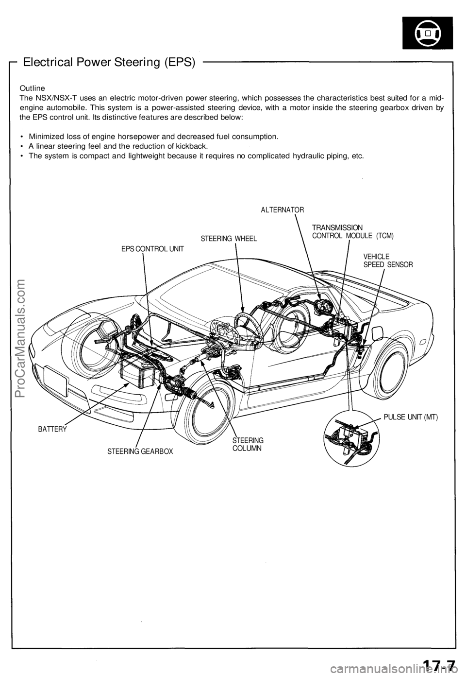
The NSX/NSX-T uses an electric motor-driven power steering, which possesses the characteristics best suited for a mid-
engine automobile. This system is a power-assisted steering device, with a motor inside the steering gearbox driven by
the EPS control unit. Its distinctive features are described below:
• Minimized loss of engine horsepower and decreased fuel consumption.
• A linear steering feel and the reduction of kickback.
• The system is compact and lightweight because it requires no complicated hydraulic piping, etc.
ALTERNATOR
TRANSMISSION
CONTROL MODULE (TCM)
EPS CONTROL UNIT
VEHICLE
SPEED SENSOR
PULSE UNIT (MT)
BATTERY
STEERING GEARBOX
STEERING WHEEL
STEERING
COLUMNProCarManuals.com
Page 408 of 1640
System Description
Major Components
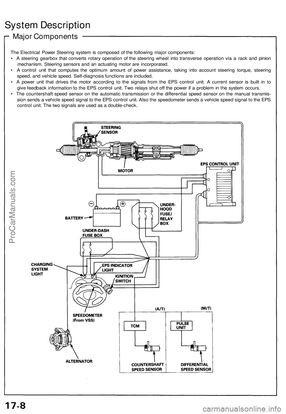
The Electrical Power Steering system is composed of the following major components:
• A steering gearbox that converts rotary operation of the steering wheel into transverse operation via a rack and pinion
mechanism. Steering sensors and an actuating motor are incorporated.
• A control unit that computes the optimum amount of power assistance, taking into account steering torque, steering
speed, and vehicle speed. Self-diagnosis functions are included.
• A power unit that drives the motor according to the signals from the EPS control unit. A current sensor is built in to
give feedback information to the EPS control unit. Two relays shut off the power if a problem in the system occurs.
• The countershaft speed sensor on the automatic transmission or the differential speed sensor on the manual transmis-
sion sends a vehicle speed signal to the EPS control unit. Also the speedometer sends a vehicle speed signal to the EPS
control unit. The two signals are used as a double-check.ProCarManuals.com
Page 409 of 1640
System Operation
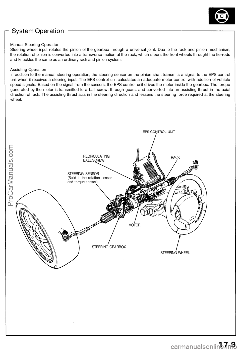
Manual Steering Operation
Steering wheel input rotates the pinion of the gearbox through a universal joint. Due to the rack and pinion mechanism,
the rotation of pinion is converted into a transverse motion at the rack, which steers the front wheels throught the tie-rods
and knuckles the same as an ordinary rack and pinion system.
Assisting Operation
In addition to the manual steering operation, the steering sensor on the pinion shaft transmits a signal to the EPS control
unit when it receives a steering input. The EPS control unit calculates an adequate motor control with addition of vehicle
speed signals. Based on the signal from the sensors, the EPS control unit drives the motor inside the gearbox. The torque
generated by the motor is transmitted to a ball screw, through gears, and converted into an assisting thrust in the axial
direction of rack. The assisting thrust acts in the steering direction and lessens the steering force required at the steering
wheel.
EPS CONTROL UNIT
RECIRCULATING
BALL SCREW
STEERING WHEEL
RACK
STEERING SENSOR
(Build in the rotation sensor
and torque sensor)
MOTOR
STEERING GEARBOXProCarManuals.com
Page 410 of 1640
System Description
Function and Operation
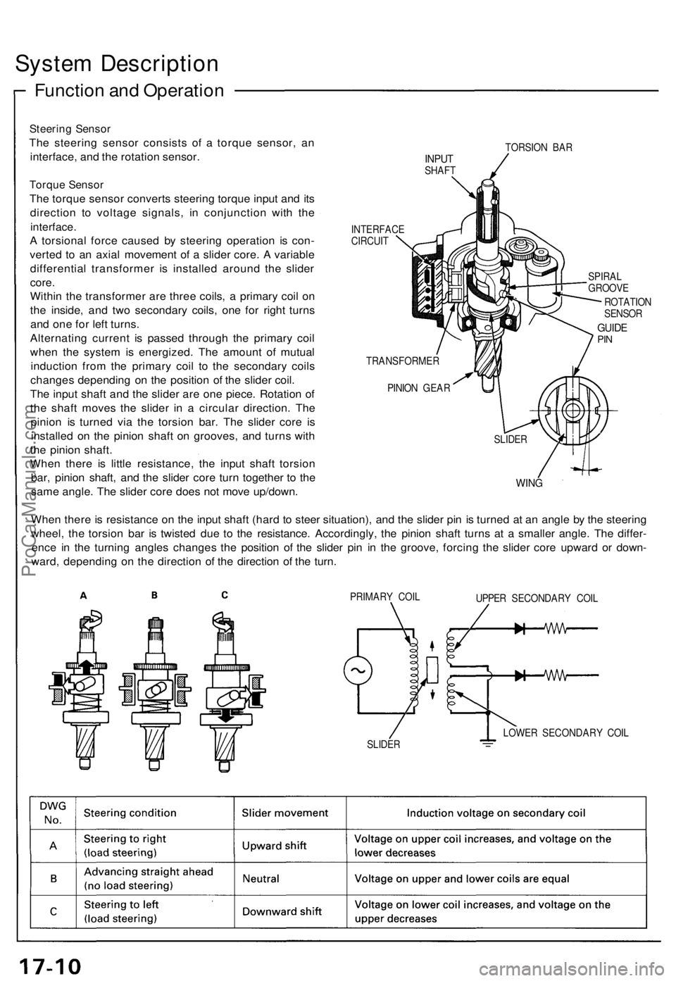
Steering Sensor
The steering sensor consists of a torque sensor, an
interface, and the rotation sensor.
Torque Sensor
The torque sensor converts steering torque input and its
direction to voltage signals, in conjunction with the
interface.
A torsional force caused by steering operation is con-
verted to an axial movement of a slider core. A variable
differential transformer is installed around the slider
core.
Within the transformer are three coils, a primary coil on
the inside, and two secondary coils, one for right turns
and one for left turns.
Alternating current is passed through the primary coil
when the system is energized. The amount of mutual
induction from the primary coil to the secondary coils
changes depending on the position of the slider coil.
The input shaft and the slider are one piece. Rotation of
the shaft moves the slider in a circular direction. The
pinion is turned via the torsion bar. The slider core is
installed on the pinion shaft on grooves, and turns with
the pinion shaft.
When there is little resistance, the input shaft torsion
bar, pinion shaft, and the slider core turn together to the
same angle. The slider core does not move up/down.
TORSION BAR
INPUT
SHAFT
INTERFACE
CIRCUIT
SPIRAL
GROOVE
ROTATION
SENSOR
GUIDE
PIN
TRANSFORMER
PINION GEAR
WING
When there is resistance on the input shaft (hard to steer situation), and the slider pin is turned at an angle by the steering
wheel, the torsion bar is twisted due to the resistance. Accordingly, the pinion shaft turns at a smaller angle. The differ-
ence in the turning angles changes the position of the slider pin in the groove, forcing the slider core upward or down-
ward, depending on the direction of the direction of the turn.
PRIMARY COIL
UPPER SECONDARY COIL
LOWER SECONDARY COIL
SLIDER
SLIDERProCarManuals.com