1991 ACURA NSX brake fluid
[x] Cancel search: brake fluidPage 72 of 1640
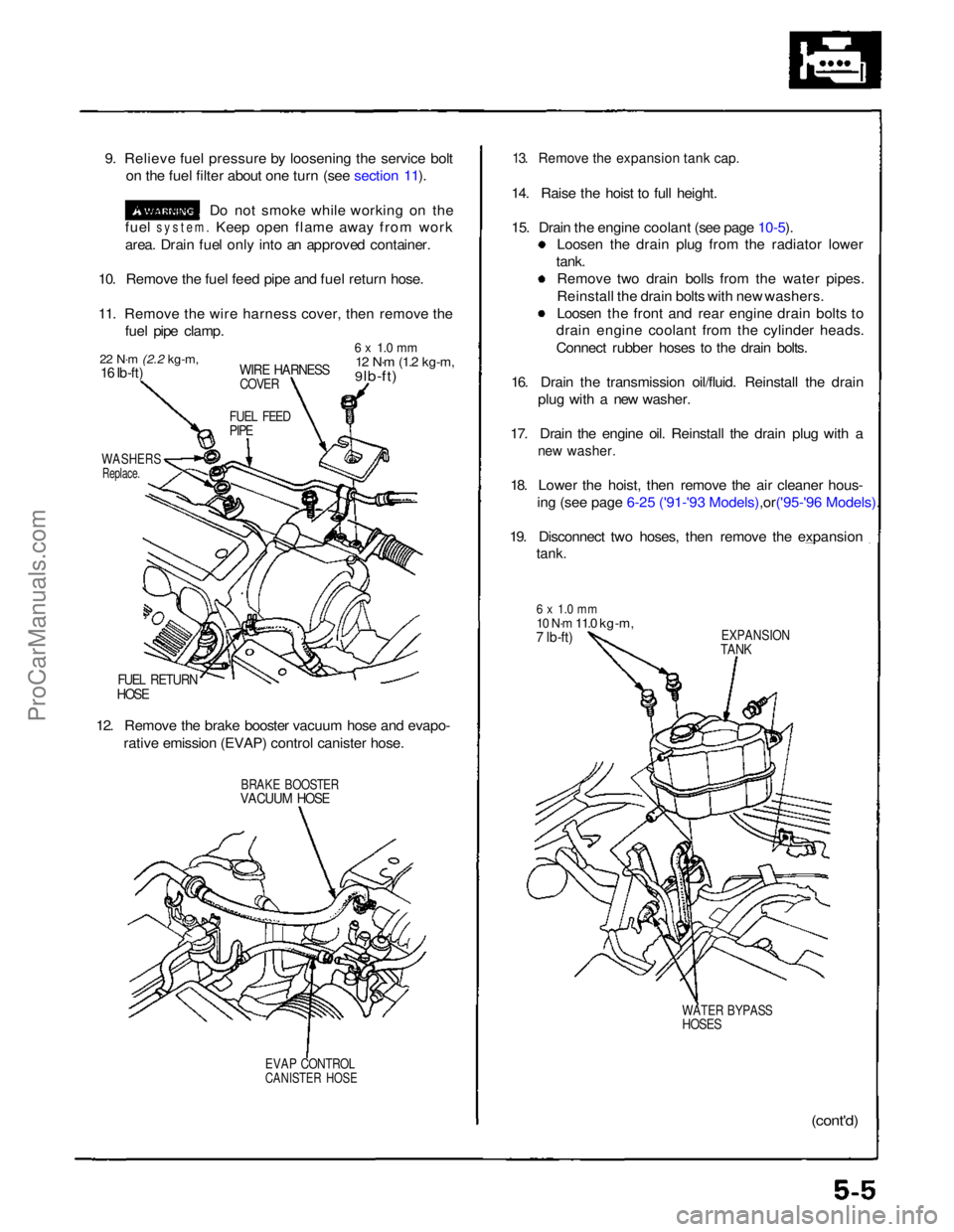
9. Relieve fuel pressure by loosening the service bolt
on the fuel filter about one turn (see section 11).
Do not smoke while working on the
fuel
system.
Keep open flame away from work
area. Drain fuel only into an approved container.
10. Remove the fuel feed pipe and fuel return hose.
11. Remove the wire harness cover, then remove the fuel pipe clamp.
22 N·m
(2.2 kg-m,
16 Ib-ft)
WIRE HARNESS
COVER
6 x 1.0 mm
12 N·m
(1.2 kg-m,
9 lb-ft)
FUEL FEED
PIPE
WASHERS
Replace.
FUEL RETURN
HOSE
12. Remove the brake booster vacuum hose and evapo- rative emission (EVAP) control canister hose.
BRAKE BOOSTER
VACUUM HOSE
EVAP CONTROL
CANISTER HOSE
13. Remove the expansion tank cap.
14. Raise the hoist to full height.
15. Drain the engine coolant (see page
10-5).
Loosen the drain plug from the radiator lower
tank. Remove two drain bolls from the water pipes.
Reinstall the drain bolts with new washers.
Loosen the front and rear engine drain bolts to
drain engine coolant from the cylinder heads.
Connect rubber hoses to the drain bolts.
16. Drain the transmission oil/fluid. Reinstall the drain plug with a new washer.
17. Drain the engine oil. Reinstall the drain plug with a
new washer.
18. Lower the hoist, then remove the air cleaner hous-
ing (see page 6-25 ('91-'93 Mode ls),or('95-'96 Models).
19. Disconnect two hoses, then remove the expansion
tank.
6 x 1.0 mm
10 N·m
11.0 kg-m,
7 lb-ft)
EXPANSION
TANK
WATER BYPASS
HOSES
(cont'd)ProCarManuals.com
Page 80 of 1640
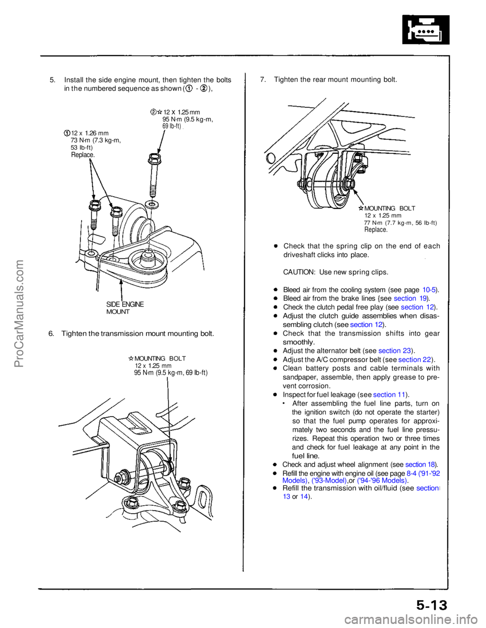
5. Install the side engine mount, then tighten the bolts
in the numbered sequence as shown ( - ),
12 x
1.26
mm
73 N·m
(7.3 kg-m,
53 Ib-ft)
Replace.
12 x
1.25
mm
95 N·m
(9.5 kg-m,
69 Ib-ft)
SIDE ENGINE
MOUNT
6. Tighten the transmission mount mounting bolt.
MOUNTING BOLT
12 x
1.25
mm
95 N·m (9.5 kg-m, 69 Ib-ft)
7. Tighten the rear mount mounting bolt.
MOUNTING BOLT
12 x
1.25
mm
77 N·m (7.7 kg-m, 56 Ib-ft)
Replace.
Check that the spring clip on the end of each
driveshaft clicks into place.
CAUTION: Use new spring clips.
Bleed air from the cooling system (see page 10-5).
Bleed air from the brake lines {see section 19).
Check the clutch pedal free play (see section 12).
Adjust the clutch guide assemblies when disas-
sembling clutch (see section 12).
Check that the transmission shifts into gear
smoothly.
Adjust the alternator belt (see section 23).
Adjust the A/C compressor belt (see section 22).
Clean battery posts and cable terminals with
sandpaper, assemble, then apply grease to pre-
vent corrosion.
Inspect for fuel leakage (see section 11). After assembling the fuel line parts, turn on
the ignition switch (do not operate the starter) so that the fuel pump operates for approxi-
mately two seconds and the fuel line pressu-
rizes. Repeat this operation two or three times
and check for fuel leakage at any point in the
fuel line.
Check and adjust wheel alignment (see section 18).
Refill the engine with engine oil (see page 8-4 ('91-'92
Models), ('93-Model),or ('94-'96 Models).
Refill the transmission with oil/fluid (see section
13 or
14).ProCarManuals.com
Page 286 of 1640
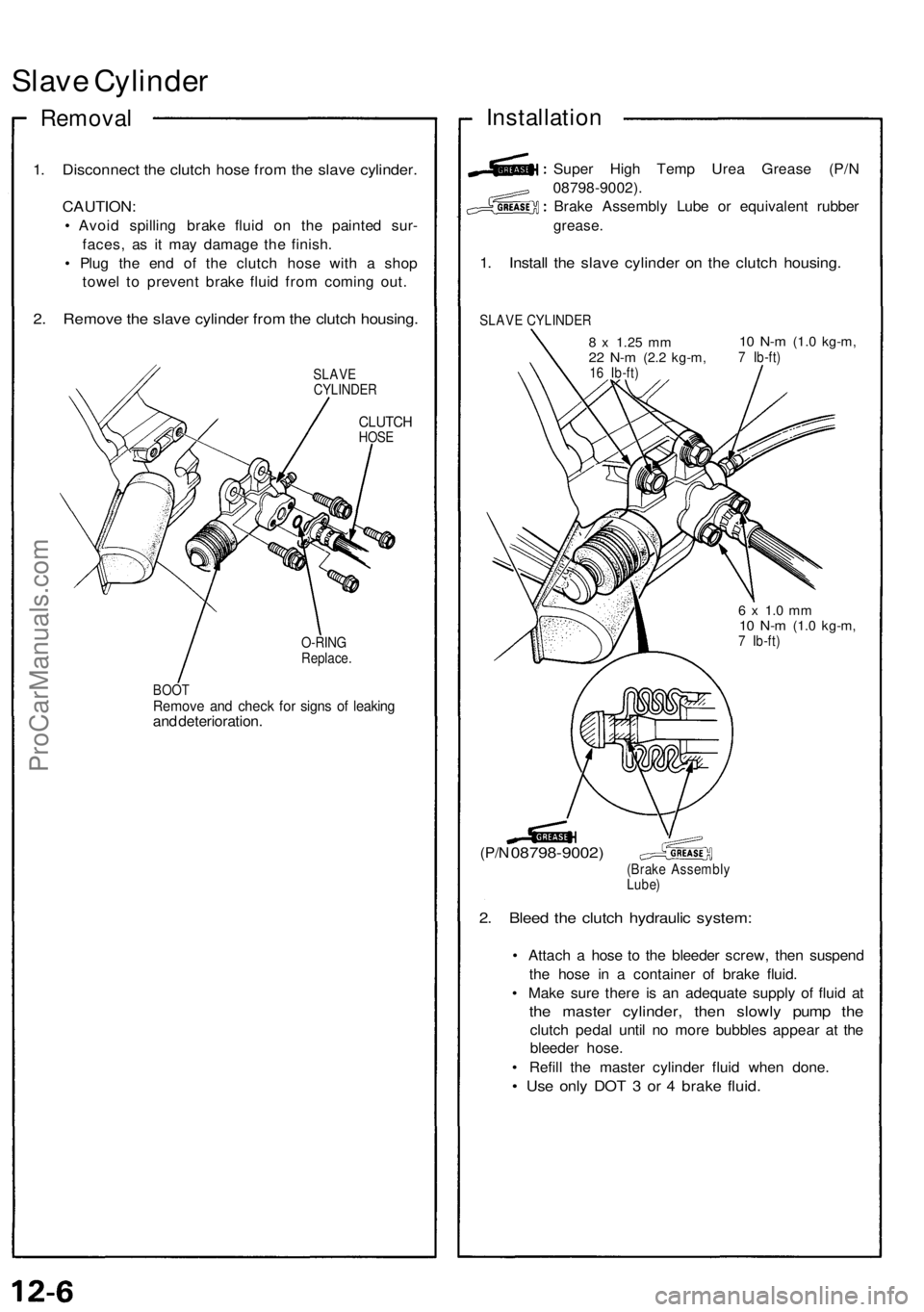
Slave Cylinde r
Remova l
1. Disconnec t th e clutc h hos e fro m th e slav e cylinder .
CAUTION :
• Avoi d spillin g brak e flui d o n th e painte d sur -
faces , a s i t ma y damag e th e finish .
• Plu g th e en d o f th e clutc h hos e wit h a sho p
towe l t o preven t brak e flui d fro m comin g out .
2. Remov e th e slav e cylinde r fro m th e clutc h housing .
SLAVE
CYLINDE R
CLUTCHHOSE
O-RIN G
Replace .
BOO T
Remov e an d chec k fo r sign s o f leakin gand deterioration .
Installation
Super Hig h Tem p Ure a Greas e (P/ N
08798-9002) .
Brake Assembl y Lub e o r equivalen t rubbe r
grease .
1. Instal l th e slav e cylinde r o n th e clutc h housing .
SLAVE CYLINDE R
8 x 1.2 5 mm22 N- m (2. 2 kg-m ,16 Ib-ft )
10 N- m (1. 0 kg-m ,7 Ib-ft )
(P/N 08798-9002 )(Brake Assembl y
Lube )
2. Blee d th e clutc h hydrauli c system :
• Attac h a hos e t o th e bleede r screw , the n suspen d
th e hos e i n a containe r o f brak e fluid .
• Mak e sur e ther e i s a n adequat e suppl y of flui d a t
the maste r cylinder , the n slowl y pum p th e
clutc h peda l unti l n o mor e bubble s appea r a t th e
bleede r hose .
• Refil l th e maste r cylinde r flui d whe n done .
• Us e onl y DO T 3 or 4 brak e fluid .
6 x 1. 0 m m10 N- m (1. 0 kg-m ,7 Ib-ft )
ProCarManuals.com
Page 494 of 1640
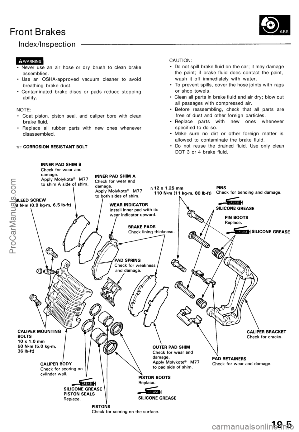
Front Brake s
Index/Inspectio n
• Neve r us e a n ai r hos e o r dr y brus h t o clea n brak e
assemblies .
• Us e a n OSHA-approve d vacuu m cleane r t o avoi d
breathin g brak e dust .
• Contaminate d brak e disc s o r pad s reduc e stoppin g
ability .
NOTE :
• Coa t piston , pisto n seal , an d calipe r bor e wit h clea n
brake fluid .
• Replac e al l rubber parts wit h ne w one s wheneve r
disassembled .
CAUTION:
• D o no t spil l brak e flui d o n th e car ; i t ma y damag e
th e paint ; i f brak e flui d doe s contac t th e paint ,
was h i t of f immediatel y wit h water .
• T o preven t spills , cove r th e hos e joint s wit h rag s
o r sho p towels .
• Clea n al l part s in brak e flui d an d ai r dry ; blo w ou t
al l passage s wit h compresse d air .
• Befor e reassembling , chec k tha t al l part s ar e
fre e o f dus t an d othe r foreig n particles .
• Replac e part s wit h ne w one s wheneve r
specifie d t o d o so .
• Mak e sur e n o dir t o r othe r foreig n matte r i s
allowe d t o contaminat e th e brak e fluid .
• D o no t reus e th e draine d fluid . Us e onl y clea n
DO T 3 o r 4 brak e fluid .
ProCarManuals.com
Page 498 of 1640
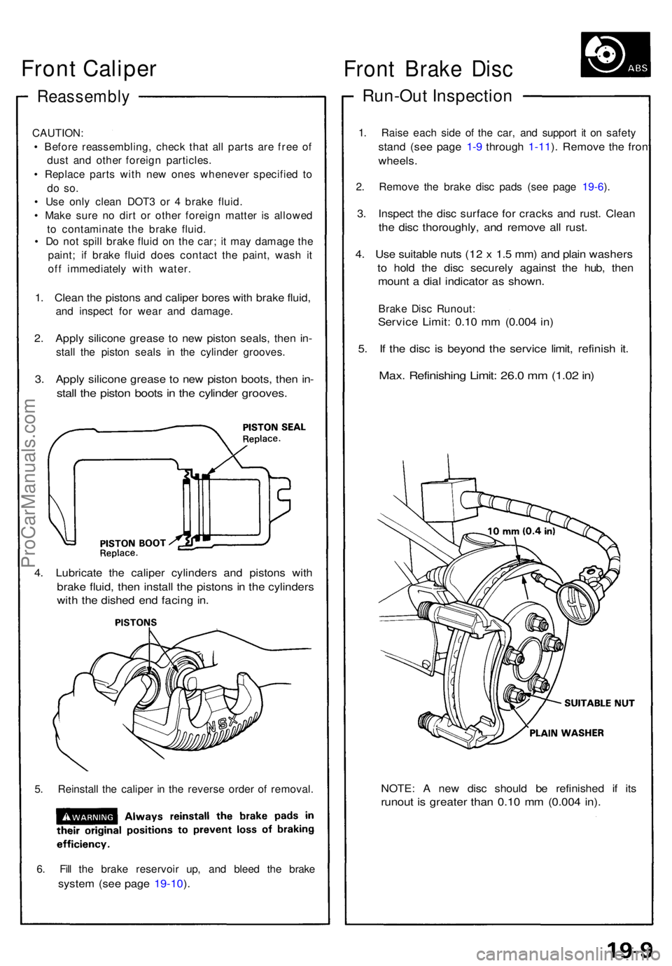
Reassembly
CAUTION:
• Befor e reassembling , chec k tha t al l part s ar e fre e o f
dus t an d othe r foreig n particles .
• Replac e part s wit h ne w one s wheneve r specifie d t o
do so .
• Us e onl y clea n DOT 3 o r 4 brak e fluid .
• Mak e sur e n o dir t o r othe r foreig n matte r i s allowe d
t o contaminat e th e brak e fluid .
• D o no t spil l brak e flui d o n th e car ; i t ma y damag e th e
paint ; i f brak e flui d doe s contac t th e paint , was h i t
of f immediatel y wit h water .
1. Clea n th e piston s an d calipe r bore s wit h brak e fluid ,
and inspec t fo r wea r an d damage .
2. Appl y silicon e greas e t o ne w pisto n seals , the n in -
stal l th e pisto n seal s i n th e cylinde r grooves .
3. Appl y silicon e greas e t o ne w pisto n boots , the n in -
stal l th e pisto n boot s in th e cylinde r grooves .
4. Lubricat e th e calipe r cylinder s an d piston s wit h
brak e fluid , the n instal l th e piston s i n th e cylinder s
with th e dishe d en d facin g in .
5. Reinstal l th e calipe r i n th e revers e orde r o f removal .
6 . Fil l th e brak e reservoi r up , an d blee d th e brak e
system (se e pag e 19-10 ).
NOTE : A ne w dis c shoul d b e refinishe d i f it s
runou t i s greate r tha n 0.1 0 m m (0.00 4 in) .
Fron t Brak e Dis c
Run-Ou t Inspectio n
1. Rais e eac h sid e o f th e car , an d suppor t i t o n safet y
stand (se e pag e 1-9 throug h 1-11 ). Remov e th e fron t
wheels .
2. Remov e th e brak e dis c pad s (se e pag e 19-6 ).
3 . Inspec t th e dis c surfac e fo r crack s an d rust . Clea n
the dis c thoroughly , an d remov e al l rust .
4. Us e suitabl e nut s (1 2 x 1. 5 mm ) an d plai n washer s
to hol d th e dis c securel y agains t th e hub , the n
moun t a dia l indicato r a s shown .
Brake Dis c Runout :
Service Limit : 0.1 0 m m (0.00 4 in )
5. I f th e dis c i s beyon d th e servic e limit , refinis h it .
Max . Refinishin g Limit : 26. 0 m m (1.0 2 in )
Front Caliper
ProCarManuals.com
Page 501 of 1640
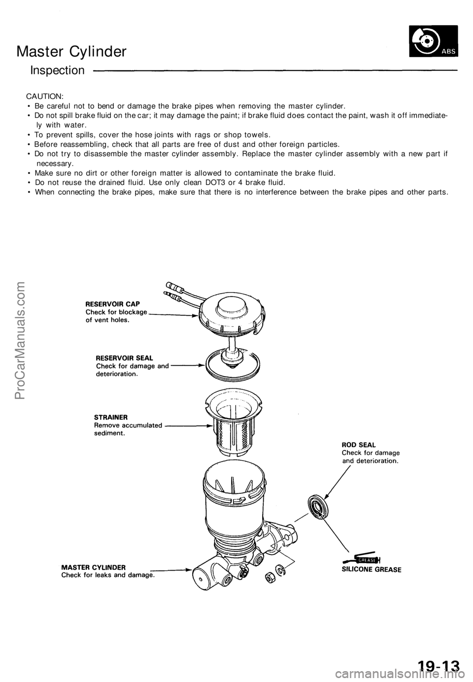
Master Cylinder
Inspection
CAUTION:
• Be careful not to bend or damage the brake pipes when removing the master cylinder.
• Do not spill brake fluid on the car; it may damage the paint; if brake fluid does contact the paint, wash it off immediate-
ly with water.
• To prevent spills, cover the hose joints with rags or shop towels.
• Before reassembling, check that all parts are free of dust and other foreign particles.
• Do not try to disassemble the master cylinder assembly. Replace the master cylinder assembly with a new part if
necessary.
• Make sure no dirt or other foreign matter is allowed to contaminate the brake fluid.
• Do not reuse the drained fluid. Use only clean DOT3 or 4 brake fluid.
• When connecting the brake pipes, make sure that there is no interference between the brake pipes and other parts.ProCarManuals.com
Page 504 of 1640
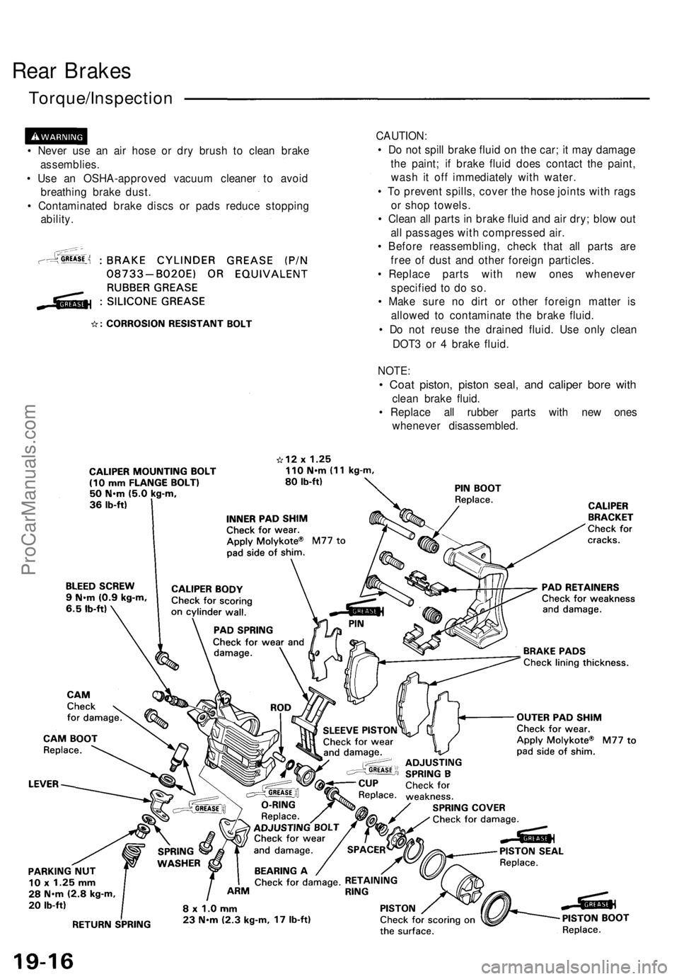
Rear Brakes
Torque/Inspection
• Never use an air hose or dry brush to clean brake
assemblies.
• Use an OSHA-approved vacuum cleaner to avoid
breathing brake dust.
• Contaminated brake discs or pads reduce stopping
ability.
CAUTION:
• Do not spill brake fluid on the car; it may damage
the paint; if brake fluid does contact the paint,
wash it off immediately with water.
• To prevent spills, cover the hose joints with rags
or shop towels.
• Clean all parts in brake fluid and air dry; blow out
all passages with compressed air.
• Before reassembling, check that all parts are
free of dust and other foreign particles.
• Replace parts with new ones whenever
specified to do so.
• Make sure no dirt or other foreign matter is
allowed to contaminate the brake fluid.
• Do not reuse the drained fluid. Use only clean
DOT3 or 4 brake fluid.
NOTE:
• Coat piston, piston seal, and caliper bore with
clean brake fluid.
• Replace all rubber parts with new ones
whenever disassembled.ProCarManuals.com
Page 517 of 1640
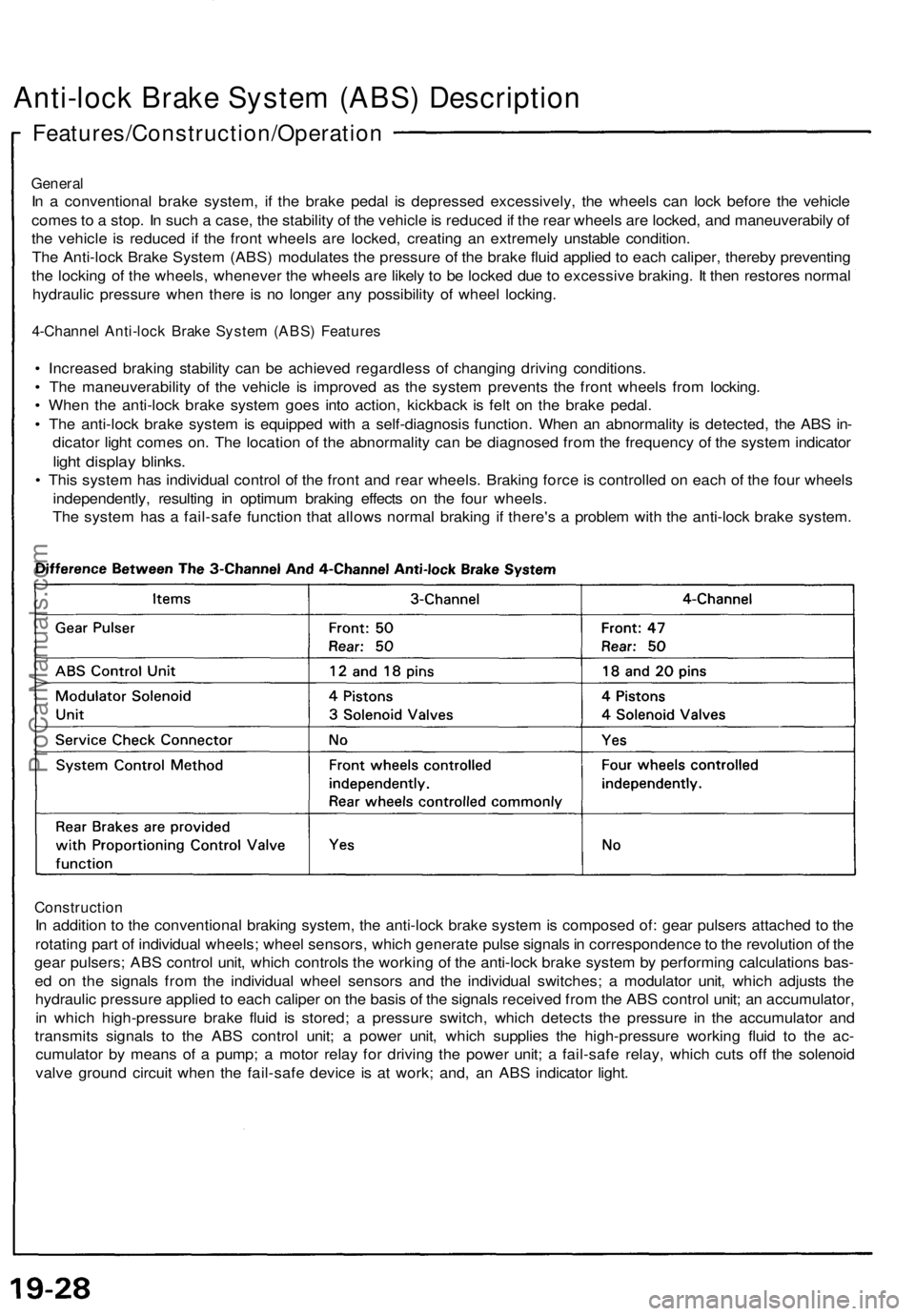
Anti-lock Brake System (ABS) Description
Features/Construction/Operation
General
In a conventional brake system, if the brake pedal is depressed excessively, the wheels can lock before the vehicle
comes to a stop. In such a case, the stability of the vehicle is reduced if the rear wheels are locked, and maneuverabily of
the vehicle is reduced if the front wheels are locked, creating an extremely unstable condition.
The Anti-lock Brake System (ABS) modulates the pressure of the brake fluid applied to each caliper, thereby preventing
the locking of the wheels, whenever the wheels are likely to be locked due to excessive braking. It then restores normal
hydraulic pressure when there is no longer any possibility of wheel locking.
4-Channel Anti-lock Brake System (ABS) Features
• Increased braking stability can be achieved regardless of changing driving conditions.
• The maneuverability of the vehicle is improved as the system prevents the front wheels from locking.
• When the anti-lock brake system goes into action, kickback is felt on the brake pedal.
• The anti-lock brake system is equipped with a self-diagnosis function. When an abnormality is detected, the ABS in-
dicator light comes on. The location of the abnormality can be diagnosed from the frequency of the system indicator
light display blinks.
• This system has individual control of the front and rear wheels. Braking force is controlled on each of the four wheels
independently, resulting in optimum braking effects on the four wheels.
The system has a fail-safe function that allows normal braking if there's a problem with the anti-lock brake system.
Construction
In addition to the conventional braking system, the anti-lock brake system is composed of: gear pulsers attached to the
rotating part of individual wheels; wheel sensors, which generate pulse signals in correspondence to the revolution of the
gear pulsers; ABS control unit, which controls the working of the anti-lock brake system by performing calculations bas-
ed on the signals from the individual wheel sensors and the individual switches; a modulator unit, which adjusts the
hydraulic pressure applied to each caliper on the basis of the signals received from the ABS control unit; an accumulator,
in which high-pressure brake fluid is stored; a pressure switch, which detects the pressure in the accumulator and
transmits signals to the ABS control unit; a power unit, which supplies the high-pressure working fluid to the ac-
cumulator by means of a pump; a motor relay for driving the power unit; a fail-safe relay, which cuts off the solenoid
valve ground circuit when the fail-safe device is at work; and, an ABS indicator light.ProCarManuals.com