Page 472 of 1640

Front Damper
Removal
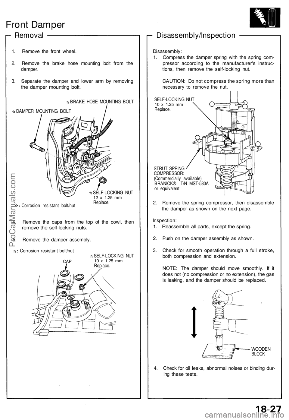
1. Remove the front wheel.
2. Remove the brake hose mounting bolt from the
damper.
3. Separate the damper and lower arm by removing
the damper mounting bolt.
BRAKE HOSE MOUNTING BOLT
DAMPER MOUNTING BOLT
Corrosion resistant bolt/nut
SELF-LOCKING NUT
12 x
1.25
mm
Replace.
4. Remove the caps from the top of the cowl, then
remove the self-locking nuts.
5. Remove the damper assembly.
Corrosion resistant bolt/nut
CAP
SELF-LOCKING NUT
10 x
1.25
mm
Replace.
Disassembly/Inspection
Disassembly:
1. Compress the damper spring with the spring com-
pressor according to the manufacturer's instruc-
tions, then remove the self-locking nut.
CAUTION: Do not compress the spring more than
necessary to remove the nut.
SELF-LOCKING NUT
10 x
1.25
mm
Replace.
STRUT SPRING
COMPRESSOR:
(Commercially available)
BRANICK® T/N MST-580A
or equivalent
2. Remove the spring compressor, then disassemble
the damper as shown on the next page.
Inspection:
1. Reassemble all parts, except the spring.
2. Push on the damper assembly as shown.
3. Check for smooth operation through a full stroke,
both compression and extension.
NOTE: The damper should move smoothly. If it
does not (no compression or no extension), the gas
is leaking, and the damper should be replaced.
WOODEN
BLOCK
4. Check for oil leaks, abnormal noises or binding dur-
ing these tests.ProCarManuals.com
Page 473 of 1640

Front Dampe r
Inspectio n
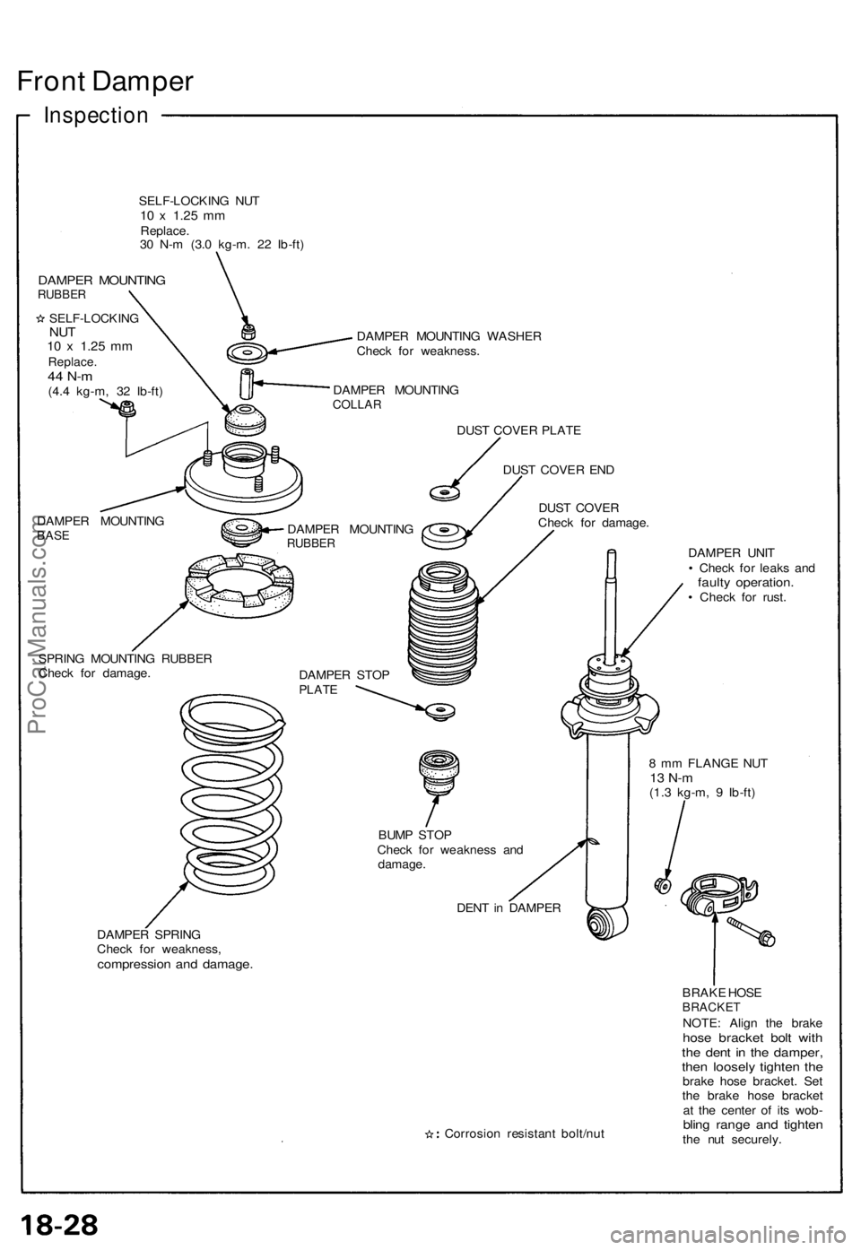
SELF-LOCKIN G NU T10 x 1.2 5 mmReplace .
3 0 N- m (3. 0 kg-m . 2 2 Ib-ft )
DAMPE R MOUNTIN GRUBBER
SELF-LOCKIN GNUT10 x 1.2 5 mmReplace .44 N- m(4.4 kg-m , 3 2 Ib-ft )
DAMPE R MOUNTIN G
BASE
DAMPE R MOUNTIN G WASHE R
Chec k fo r weakness .
DAMPE R MOUNTIN G
COLLAR
DAMPE R MOUNTIN GRUBBER
DUST COVE R PLAT E
DUS T COVE R EN D
DUS T COVE R
Chec k fo r damage .
SPRIN G MOUNTIN G RUBBE R
Chec k fo r damage .
DAMPER STO P
PLAT E
BUMP STO P
Chec k fo r weaknes s an d
damage .
DENT in DAMPE R
DAMPE R SPRIN G
Chec k fo r weakness ,
compression an d damage .
DAMPER UNI T
• Chec k fo r leak s an d
fault y operation .• Chec k fo r rust .
8 m m FLANG E NU T
13 N- m(1.3 kg-m , 9 Ib-ft )
Corrosio n resistan t bolt/nu t BRAK
E HOS E
BRACKE TNOTE: Alig n th e brak ehose bracke t bol t wit hthe den t i n th e damper ,then loosel y tighte n th ebrak e hos e bracket . Se t
th e brak e hos e bracke t
a t th e cente r o f it s wob -
bling rang e an d tighte nthe nu t securely .
ProCarManuals.com
Page 487 of 1640
Rear Damper
Disassembly/Inspection
Disassembly:
1. Compress the damper spring with the spring com-
pressor according to the manufacturer's instruc-
tions, then remove the self-locking nut.
CAUTION: Do not compress the spring more than
necessary to remove the nut.
SELF-LOCKING NUT
10 x
1.25
mm
Replace.
STRUT SPRING COMPRESSOR:
(Commercially available)
BRANICK® T/N MST-580A or equivalent
2. Remove the spring compressor, then disassemble
the damper as shown on the next page.
Inspection:
1. Reassemble all parts, except the spring.
2. Push on the damper assembly as shown.
3. Check for smooth operation through a full stroke,
both compression and extension.
NOTE: The damper should move smoothly.
If it does not (no compression or no extension), the
gas is leaking, and the damper should be replaced.
WOODEN
BLOCK
4. Check for oil leaks, abnormal noises or binding dur-
ing these tests.ProCarManuals.com
Page 488 of 1640
Inspection
SELF-LOCKING NUT
10 x
1.25
Replace.
DAMPER
MOUNTING RUBBER
SELF-LOCKING
NUT
10 x
1.25
mm
Replace.
54 N-m
(5.4 kg-m, 39 Ib-ft)
DAMPER
MOUNTING
WASHER
DAMPER
MOUNTING
COLLAR
DAMPER
MOUNTING BASE
BUMP STOP
PLATE
DAMPER
MOUNTING
RUBBER
SPRING MOUNTING
RUBBER
Check for damage
and cracks.
BUMP STOP
PLATE
DUST COVER
SLEEVE
Check for damage.
DAMPER SPRING
Check for weakened
compression and damage.
BUMP STOP
Check for weakness,
and damage.
DAMPER UNIT
• Check for oil leak
and faulty operation.
• Check for rust.
Corrosion resistant bolt/nutProCarManuals.com
Page 978 of 1640

This engine has the following new features.
Type
Displacement
Bore x Stroke
Compression Ratio
Cam, Valve Mechanism
Valve Train
Fuel Supply System Water-cooled V6—90° Cross Flow
2,977 cm3(181.6cu-in)
90 x 78 mm
(3.54
x
3.07
in)
10.2
Dual Overhead Camshafts, VTEC Belt Driven
Sequential Multiport Fuel Injection (SFI)VTEC; High output and a broad power band is achieved through control of low-speed and high-speed valve operation
by the Engine Control Module (ECM).
(Two knock sensors are used to detect octane level of the fuel.)
Titanium connecting rods ; Accomodate high rotation speed and high output. Titanium material of light weight and
high strength is used for the connecting rods.
(Strength is at the same level as iron.)
(Weight is about 30% lighter than iron.)
New mechanism to the intake system; Increased low and middle speed torque and higher output can be achieved by
switching the chamber volume of the intake manifold according to engine speed. This is electronically-controlled.
Cooling system for the mid-ship engine:
Radiator located in front compartment (An aluminum alloy radiator and pipes made of aluminum alloy)
Engine room cooling fan
Expansion tank
The cylinder block is highly rigid with deep water jackets. In order to achieve lighter weight, magnesium is used for the following parts: Cylinder head coverIntake manifold cover
Intake manifold chamber
Major SpecificationsProCarManuals.com