1991 ACURA NSX stop start
[x] Cancel search: stop startPage 420 of 1640
Troubleshooting Precautions
EPS Indicator Light
Under normal conditions, the EPS indicator light in the gauge assembly comes on when the ignition switch is turned to
the ON (II) position, then goes off after the engine is started. This indicates that the bulb and its circuits are operating cor-
rectly. If there is any trouble in the system, the EPS indicator light turns on during driving, and the power steering assist is
turned off. When the EPS indicator light comes on, the control unit memorizes the DTC. In this case, the control unit does
not activate the EPS system after the engine starts again but it keeps the EPS indicator light on.
Diagnostic Trouble Code (DTC)
• The lowest DTC is indicated first.
• The DTCs continue blinking until the ignition switch is turned off.
• The DTCs are erased from the control unit when the EPS control unit VBU power supply or connector is disconnected.
• The EPS system can be reset and the control unit's memory can be erased by disconnecting the CLOCK (7.5 A) fuse for
more than ten seconds.
Self-diagnosis:
The CPU (central processing unit) controls the following when it detects a problem during self-diagnosis:
1. Turns the EPS indicator light ON to alert the driver.
2. Power assist stops, and normal manual steering operation resumes (except DTC 21 and DTC 33).
3. The EPS control unit memorizes the diagnostic trouble code (DTC).
4. After the DTC is stored in the control unit, the CPU stops self-diagnosis.
Troubleshooting:
• Before starting the troubleshooting, clear the DTC by disconnecting the CLOCK (7.5 A) fuse for ten seconds or more,
and test-drive the car. Check that the symptom of the trouble appears again, and then troubleshoot. If the problem is an
intermittent problem, the system does not become active after the engine starts even though the problem is solved.
• When both EPS indicator light and A/T "D" indicator light come on, perform the A/T troubleshooting first.
• When the customer's reported problem cannot be verified in the car, ask the customer about the conditions when the
EPS indicator light came ON, then test-drive the car under those conditions, if possible. If the EPS indicator light does
not come ON during the test, check for loose connections or poor contacts at the connectors by wiggling the harness,
etc.
• The connector terminal numbers are viewed from the wire side for the female terminals and from the terminal side for
the male terminals.
• After the repair, test-drive the car and check that the EPS indicator light does not come ON again during the test. (Refer
to the Symptom-to-System Chart for diagnostic period.)ProCarManuals.com
Page 423 of 1640
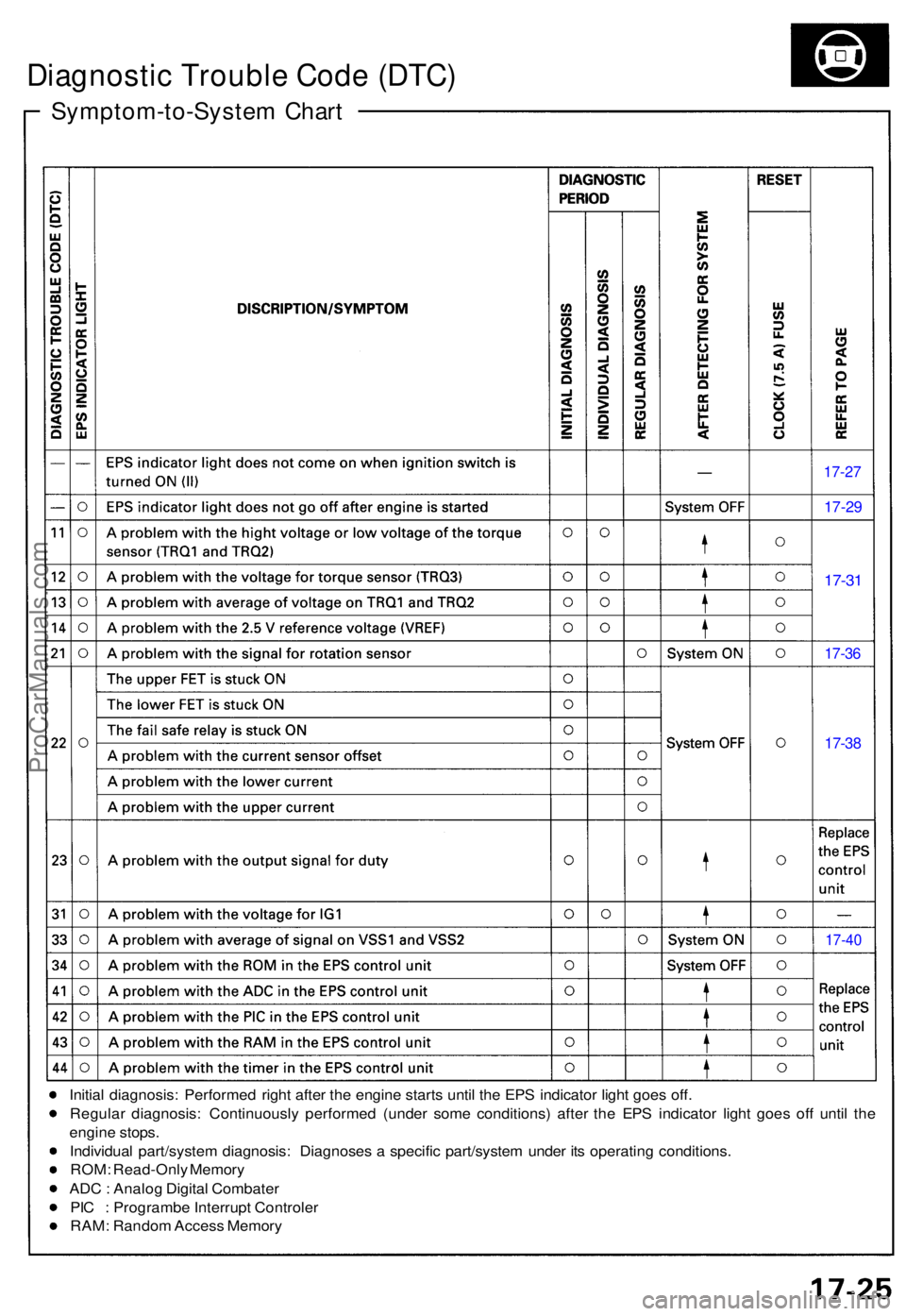
Symptom-to-System Char t
Diagnosti c Troubl e Cod e (DTC )
17-27
17-29
17-31
17-3 6
17-38
17-4 0
Initia l diagnosis : Performe d righ t afte r th e engin e start s unti l th e EP S indicato r ligh t goe s off .
Regula r diagnosis : Continuousl y performe d (unde r som e conditions ) afte r th e EP S indicator light goe s of f unti l th e
engin e stops .
Individua l part/syste m diagnosis : Diagnose s a specifi c part/syste m unde r it s operatin g conditions .
ROM : Read-Onl y Memor y
AD C : Analo g Digita l Combate r
PI C : Programb e Interrup t Controle r
RAM : Rando m Acces s Memor y
ProCarManuals.com
Page 528 of 1640
ALB Checker
Function Test (cont'd)
4. Turn the Mode Selector switch further to "2". 5. Depress the brake pedal firmly and push the Start
Test switch
The ABS indicator light should not go on while the
Test in Progress light is ON. There should bekickback on the brake pedal. If not as described, go
to troubleshooting, page 19-44 ('91-'92) ('93-'96).
NOTE: The operation sequence simulated lby
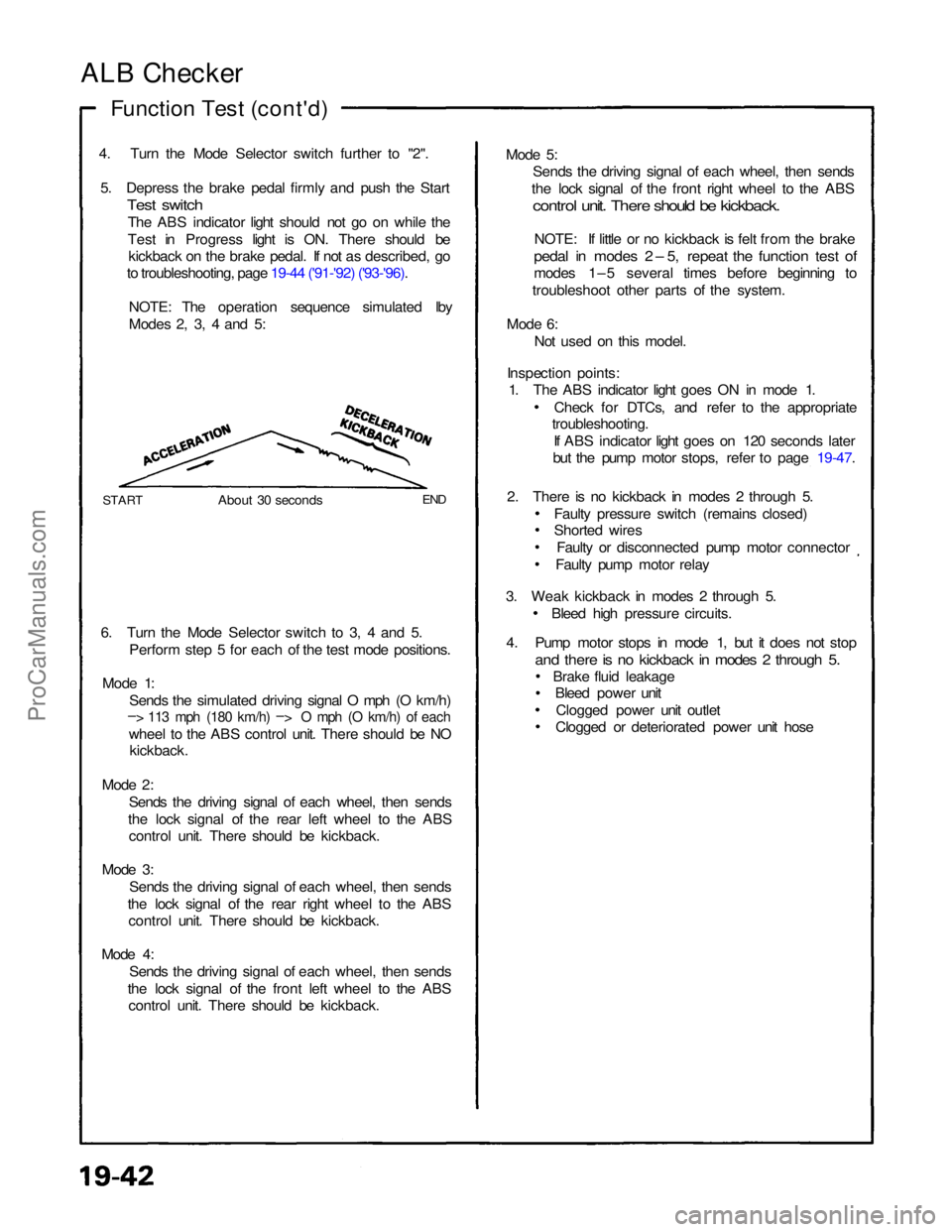
Modes 2, 3, 4 and 5:
START
About 30 seconds
END
6. Turn the Mode Selector switch to 3, 4 and 5. Perform step 5 for each of the test mode positions.
Mode 1: Sends the simulated driving signal O mph (O km/h)
– > 113 mph (180 km/h) –
>
O mph (O km/h) of each
wheel to the ABS control unit. There should be NO
kickback.
Mode 2: Sends the driving signal of each wheel, then sends
the lock signal of the rear left wheel to the ABS control unit. There should be kickback.
Mode 3: Sends the driving signal of each wheel, then sends
the lock signal of the rear right wheel to the ABS control unit. There should be kickback.
Mode 4: Sends the driving signal of each wheel, then sends
the lock signal of the front left wheel to the ABS control unit. There should be kickback. Mode 5:
Sends the driving signal of each wheel, then sends
the lock signal of the front right wheel to the ABS
control unit. There should be kickback.
NOTE: If little or no kickback is felt from the brake
pedal in modes 2 – 5, repeat the function test of
modes 1–5 several times before beginning to
troubleshoot other parts of the system.
Mode 6: Not used on this model.
Inspection points: 1. The ABS indicator light goes ON in mode 1.
Check for DTCs, and refer to the appropriate
troubleshooting.
If ABS indicator light goes on 120 seconds later
but the pump motor stops, refer to page 19-47.
2. There is no kickback in modes 2 through 5. Faulty pressure switch (remains closed)
Shorted wiresFaulty or disconnected pump motor connector
Faulty pump motor relay
3. Weak kickback in modes 2 through 5. Bleed high pressure circuits.
4. Pump motor stops in mode 1, but it does not stop
and there is no kickback in modes 2 through 5.
Brake fluid leakageBleed power unit
Clogged power unit outlet
Clogged or deteriorated power unit hoseProCarManuals.com
Page 530 of 1640
Troubleshooting
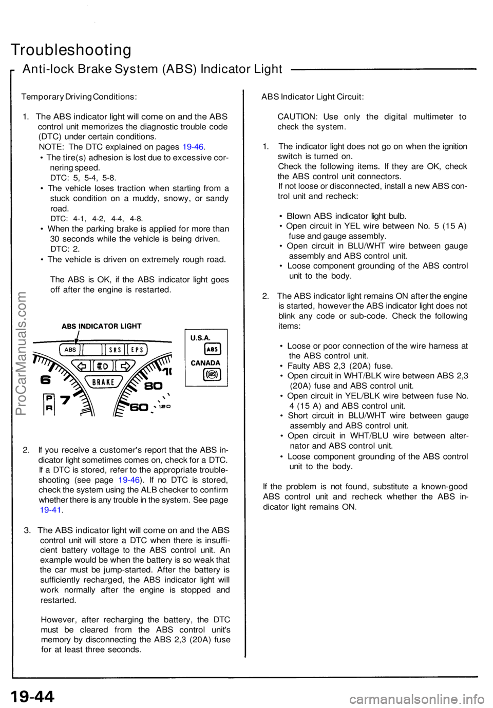
Anti-lock Brak e Syste m (ABS ) Indicato r Ligh t
Temporar y Drivin g Conditions :
1. Th e AB S indicato r ligh t wil l com e o n an d th e AB S
contro l uni t memorize s th e diagnosti c troubl e cod e
(DTC ) unde r certai n conditions .
NOTE : Th e DT C explaine d o n page s 19-46 .
• Th e tire(s ) adhesio n is los t du e to excessiv e cor -
nerin g speed .
DTC: 5, 5-4 , 5-8 .
• Th e vehicl e lose s tractio n whe n startin g fro m a
stuc k conditio n o n a muddy , snowy , o r sand y
road.
DTC: 4-1 , 4-2 , 4-4 , 4-8 .
• Whe n th e parkin g brak e is applie d fo r mor e tha n
3 0 second s whil e th e vehicl e i s bein g driven .
DTC: 2.
• Th e vehicl e is drive n o n extremel y roug h road .
Th e AB S is OK , i f th e AB S indicato r ligh t goe s
of f afte r th e engin e i s restarted .
2 . I f yo u receiv e a customer' s repor t tha t th e AB S in -
dicato r ligh t sometime s come s on , chec k fo r a DTC .
I f a DT C is stored , refe r t o th e appropriat e trouble -
shootin g (se e pag e 19-46 ). I f n o DT C is stored ,
chec k th e syste m usin g th e AL B checke r t o confir m
whethe r ther e is an y troubl e in th e system . Se e pag e
19-41 .
3. Th e AB S indicato r ligh t wil l com e o n an d th e AB S
contro l uni t wil l stor e a DT C whe n ther e i s insuffi -
cien t batter y voltag e t o th e AB S contro l unit . A n
exampl e woul d b e whe n th e batter y is s o wea k tha t
th e ca r mus t b e jump-started . Afte r th e batter y i s
sufficientl y recharged , th e AB S indicato r ligh t wil l
wor k normall y afte r th e engin e i s stoppe d an d
restarted .
However , afte r rechargin g th e battery , th e DT C
mus t b e cleare d fro m th e AB S contro l unit' s
memor y b y disconnectin g th e AB S 2, 3 (20A ) fus e
fo r a t leas t thre e seconds . AB
S Indicato r Ligh t Circuit :
CAUTION : Us e onl y th e digita l multimete r t o
chec k th e system .
1. Th e indicato r ligh t doe s no t g o o n whe n th e ignitio n
switc h i s turne d on .
Chec k th e followin g items . I f the y ar e OK , chec k
th e AB S contro l uni t connectors .
I f no t loos e o r disconnected , instal l a ne w AB S con -
tro l uni t an d recheck :
• Blow n AB S indicato r ligh t bulb .
• Ope n circui t i n YE L wir e betwee n No . 5 (1 5 A )
fus e an d gaug e assembly .
• Ope n circui t i n BLU/WH T wir e betwee n gaug e
assembl y an d AB S contro l unit .
• Loos e componen t groundin g of the AB S contro l
uni t t o th e body .
2 . Th e AB S indicato r ligh t remain s O N afte r th e engin e
i s started , howeve r th e AB S indicato r ligh t doe s no t
blin k an y cod e o r sub-code . Chec k th e followin g
items :
• Loos e o r poo r connectio n of the wir e harnes s a t
th e AB S contro l unit .
• Fault y AB S 2, 3 (20A ) fuse .
• Ope n circui t i n WHT/BL K wir e betwee n AB S 2, 3
(20A ) fus e an d AB S contro l unit .
• Ope n circui t i n YEL/BL K wir e betwee n fus e No .
4 (1 5 A ) an d AB S contro l unit .
• Shor t circui t i n BLU/WH T wir e betwee n gaug e
assembl y an d AB S contro l unit .
• Ope n circui t i n WHT/BL U wir e betwee n alter -
nato r an d AB S contro l unit .
• Loos e componen t groundin g o f th e AB S contro l
uni t t o th e body .
I f th e proble m is no t found , substitut e a known-goo d
AB S contro l uni t an d rechec k whethe r th e AB S in -
dicato r ligh t remain s ON .
ProCarManuals.com
Page 531 of 1640
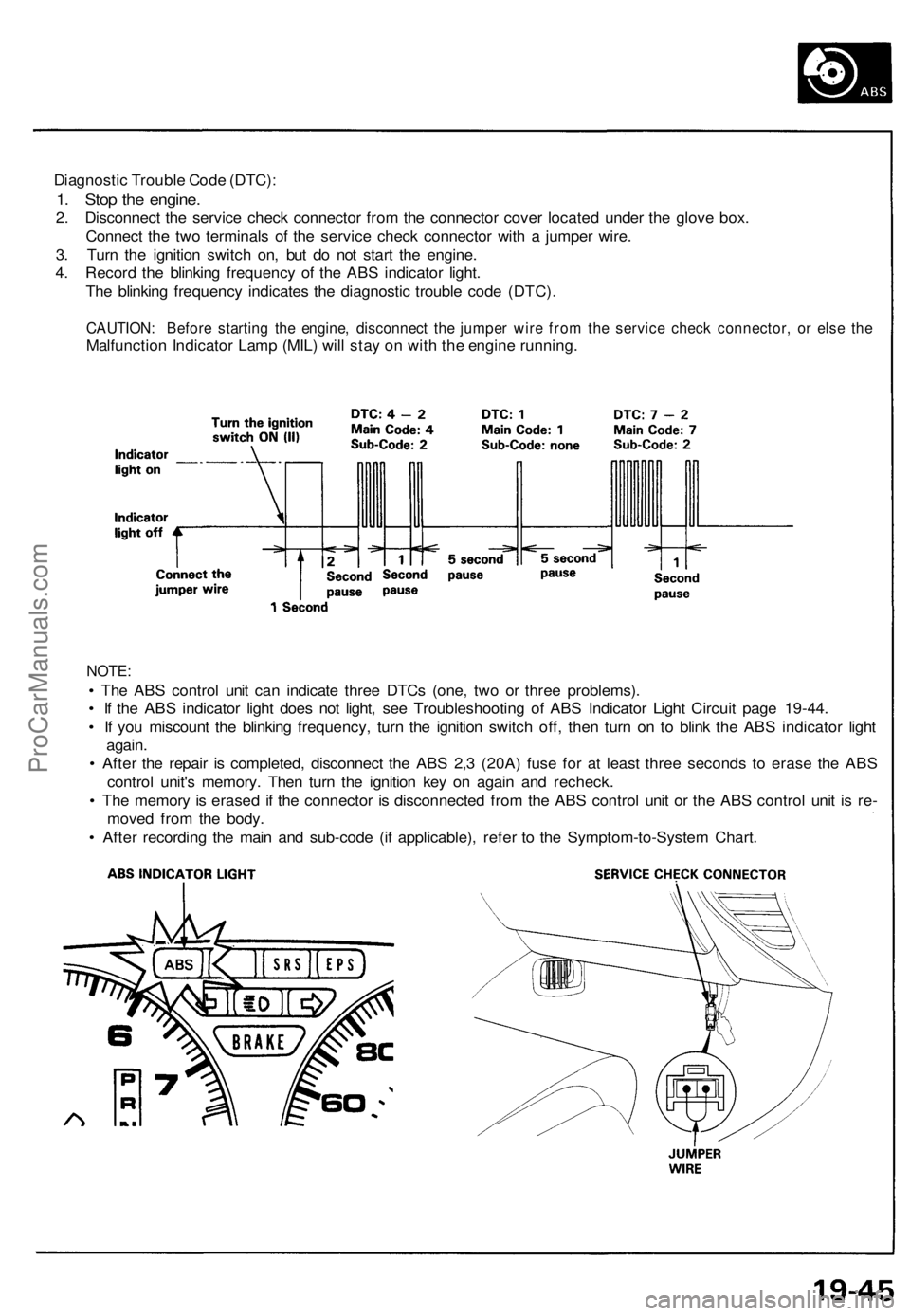
Diagnostic Trouble Code (DTC):
1. Stop the engine.
2. Disconnect the service check connector from the connector cover located under the glove box.
Connect the two terminals of the service check connector with a jumper wire.
3. Turn the ignition switch on, but do not start the engine.
4. Record the blinking frequency of the ABS indicator light.
The blinking frequency indicates the diagnostic trouble code (DTC).
CAUTION: Before starting the engine, disconnect the jumper wire from the service check connector, or else the
Malfunction Indicator Lamp (MIL) will stay on with the engine running.
NOTE:
• The ABS control unit can indicate three DTCs (one, two or three problems).
• If the ABS indicator light does not light, see Troubleshooting of ABS Indicator Light Circuit page 19-44.
• If you miscount the blinking frequency, turn the ignition switch off, then turn on to blink the ABS indicator light
again.
• After the repair is completed, disconnect the ABS 2,3 (20A) fuse for at least three seconds to erase the ABS
control unit's memory. Then turn the ignition key on again and recheck.
• The memory is erased if the connector is disconnected from the ABS control unit or the ABS control unit is re-
moved from the body.
• After recording the main and sub-code (if applicable), refer to the Symptom-to-System Chart.ProCarManuals.com
Page 686 of 1640
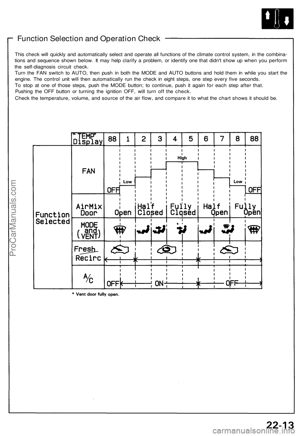
Function Selection and Operation Check
This check will quickly and automatically select and operate all functions of the climate control system, in the combina-
tions and sequence shown below. It may help clarify a problem, or identify one that didn't show up when you perform
the self-diagnosis circuit check.
Turn the FAN switch to AUTO, then push in both the MODE and AUTO buttons and hold them in while you start the
engine. The control unit will then automatically run the check in eight steps, one step every five seconds.
To stop at one of those steps, push the MODE button; to continue, push it again for each step after that.
Pushing the OFF button or turning the ignition OFF, will turn off the check.
Check the temperature, volume, and source of the air flow, and compare it to what the chart shows it should be.ProCarManuals.com
Page 948 of 1640
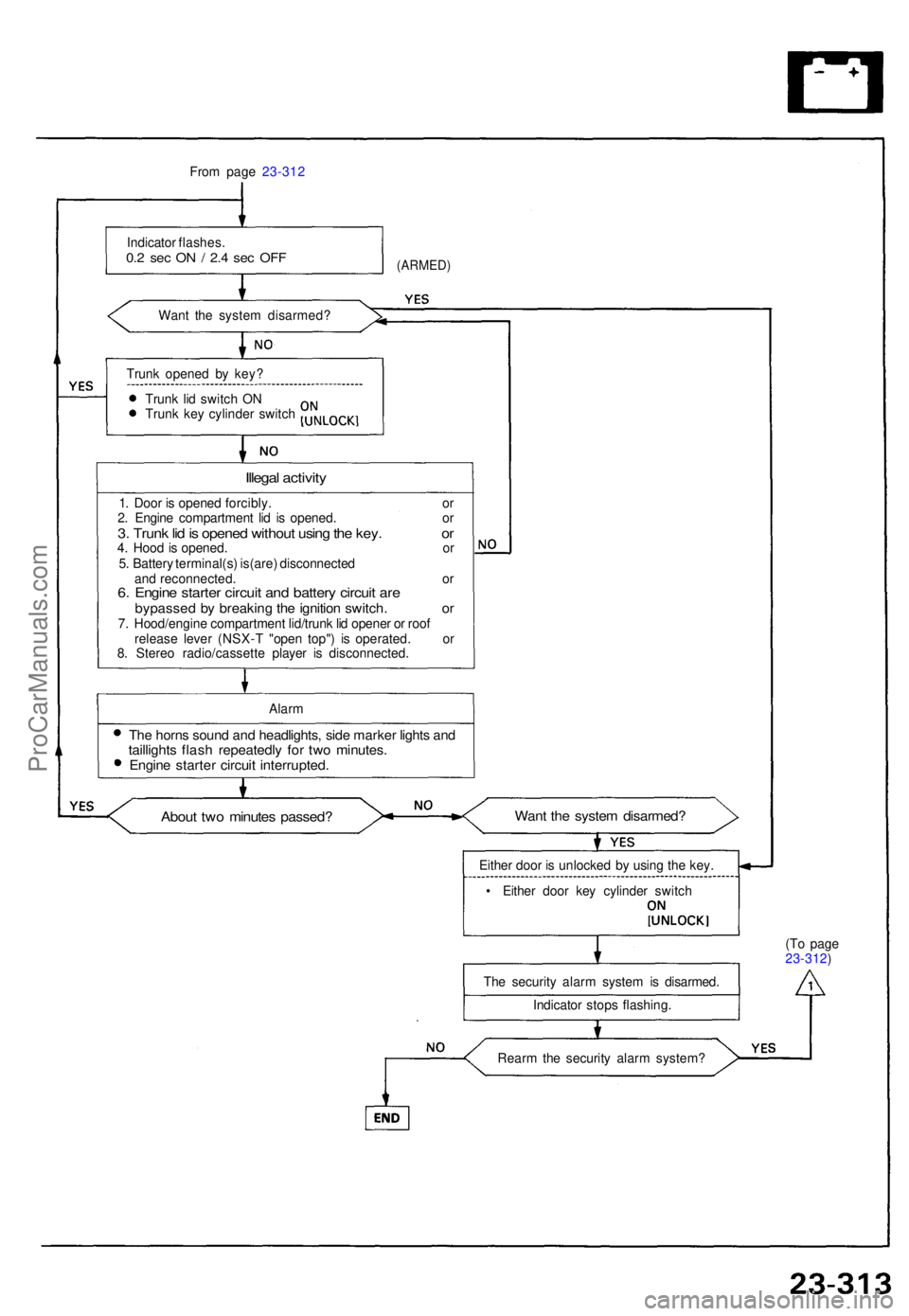
From pag e 23-31 2
Indicato r flashes .
0.2 se c O N / 2. 4 se c OF F
Wan t th e syste m disarmed ?
(ARMED)
Trunk opene d b y key ?
Trun k li d switc h O N
Trun k ke y cylinde r switc h
Illegal activit y
1. Doo r i s opene d forcibly . o r
2 . Engin e compartmen t li d i s opened . o r
3. Trun k li d is opene d withou t usin g th e key . o r4. Hoo d is opened . o r
5 . Batter y terminal(s ) is(are ) disconnecte d
an d reconnected . o r
6. Engin e starte r circui t an d batter y circui t ar ebypasse d b y breakin g th e ignitio n switch . o r7. Hood/engin e compartmen t lid/trun k li d opene r o r roo f
releas e leve r (NSX- T "ope n top" ) i s operated . o r
8 . Stere o radio/cassett e playe r i s disconnected .
Alar m
The horn s soun d an d headlights , sid e marke r light s an dtaillight s flas h repeatedl y fo r tw o minutes .Engine starte r circui t interrupted .
About tw o minute s passed ?Want th e syste m disarmed ?
Either doo r i s unlocke d b y usin g th e key .
• Eithe r doo r ke y cylinde r switc h
Th e securit y alar m syste m is disarmed .
Indicato r stop s flashing . (T
o pag e
23-312 )
Rear m th e securit y alar m system ?
ProCarManuals.com
Page 998 of 1640
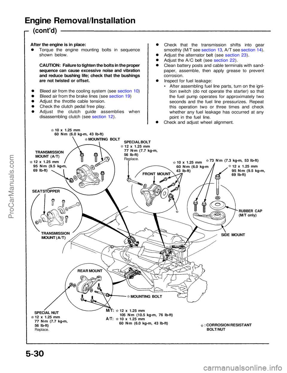
Engine Removal/Installation
(cont'd)
Torque the engine mounting bolts in sequenceshown below.
CAUTION: Failure to tighten the bolts in the proper
sequence can cause excessive noise and vibration
and reduce bushing life; check that the bushings
are not twisted or offset.
Bleed air from the cooling system (see section 10)
Bleed air from the brake lines (see section 19)
Adjust the throttle cable tension.
Check the clutch pedal free play.
Adjust the clutch guide assemblies when
disassembling clutch (see section 12). Check that the transmission shifts into gear
smoothly (M/T see section 13, A/T see section 14).
Adjust the alternator belt (see section 23).
Adjust the A/C belt (see section 22).
Clean battery posts and cable terminals with sand-
paper, assemble, then apply grease to prevent
corrosion.
Inspect for fuel leakage:
• After assembling fuel line parts, turn on the igni- tion switch (do not operate the starter) so that
the fuel pump operates for approximately two seconds and the fuel line pressurizes. Repeat
this operation two or three times and check whether any fuel leakage has occurred at any
point in the fuel line.
Check and adjust wheel alignment.
10 x
1.25
mm
60 N .
m (6.0 kg-m, 43 Ib-ft)
MOUNTING BOLT SPECIAL BOLT
12 x
1.25
mm
77 N .
m
(7.7 kg-m,
56 Ib-ft)
Replace.
10 x
1.25
mm
60 N .
m
(6.0 kg-m
43 Ib-ft) 73 N.m (7.3 kg-m, 53 Ib-ft)
12 x
1.25
mm
95 N .
m
(9.5 kg-m,
69 Ib-ft)
RUBBER CAP
(M/T only)
SIDE MOUNT
: CORROSION RESISTANT
BOLT/NUT
12 x
1.25
mm
105 N .
m (10.5 kg-m, 76 Ib-ft)
10 x
1.25
mm
60 N .
m (6.0 kg-m, 43 Ib-ft) MOUNTING BOLT FRONT MOUNT
TRANSMISSION
MOUNT (A/T)
12 x
1.25
mm
95 N .
m
(9.5 kg-m,
69 Ib-ft)
SEAT STOPPER
TRANSMISSION
MOUNT (A/T)
REAR MOUNT
SPECIAL NUT
12 x
1.25
mm
77 N .
m
(7.7 kg-m,
56 Ib-ft)
Replace.
M/T:
A/T:
After the engine is in place:ProCarManuals.com