Page 93 of 1640
Timing Belt
Installation
Install the timing belt in the reverse order of removal;
Only key points are described here.
NOTE: Clean the middle and lower covers before instal-
lation.
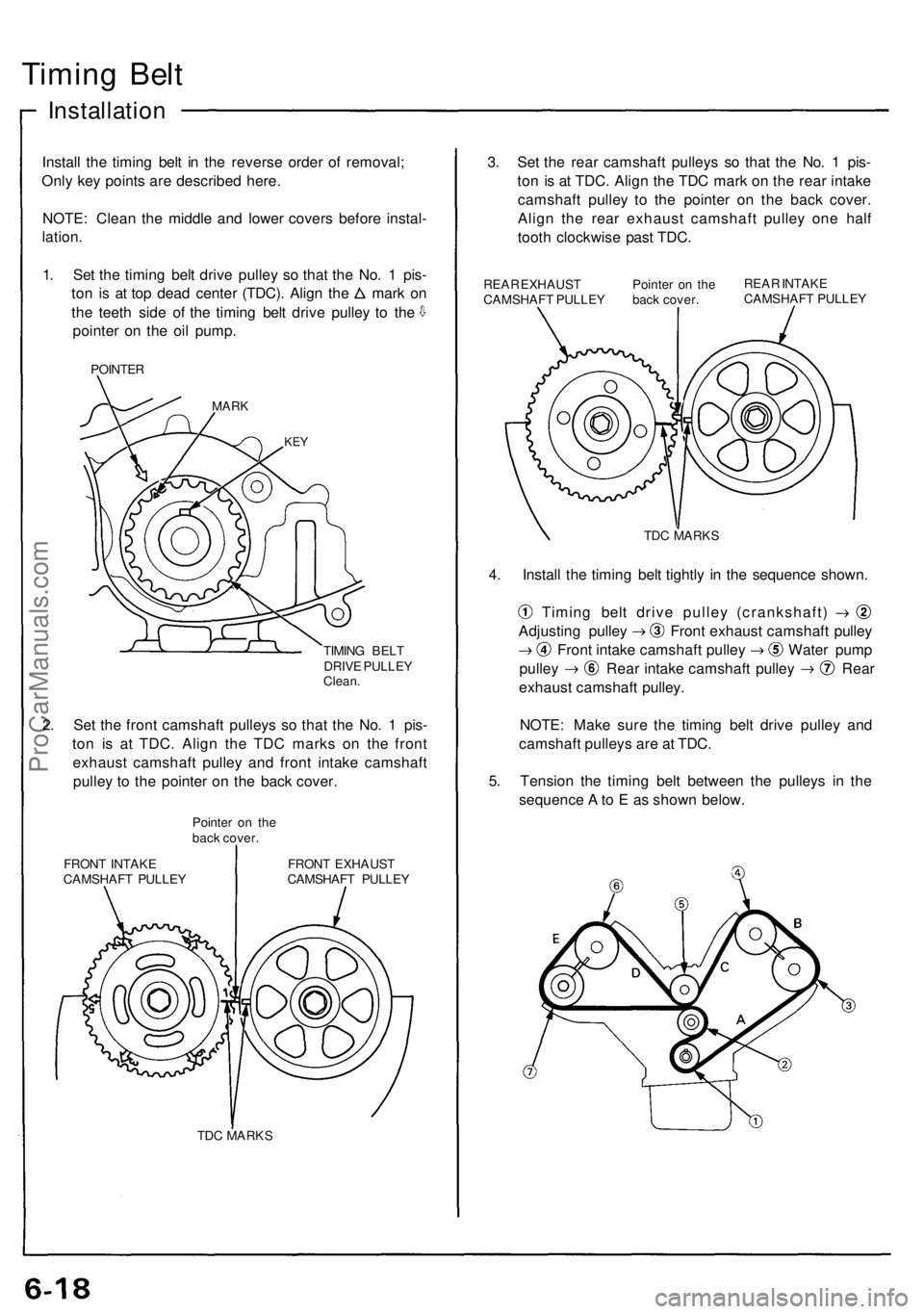
1. Set the timing belt drive pulley so that the No. 1 pis-
ton is at top dead center (TDC). Align the mark on
the teeth side of the timing belt drive pulley to the
pointer on the oil pump.
POINTER
MARK
KEY
TIMING BELT
DRIVE PULLEY
Clean.
2. Set the front camshaft pulleys so that the No. 1 pis-
ton is at TDC. Align the TDC marks on the front
exhaust camshaft pulley and front intake camshaft
pulley to the pointer on the back cover.
Pointer on the
back cover.
FRONT INTAKE
CAMSHAFT PULLEY
FRONT EXHAUST
CAMSHAFT PULLEY
TDC MARKS
3. Set the rear camshaft pulleys so that the No. 1 pis-
ton is at TDC. Align the TDC mark on the rear intake
camshaft pulley to the pointer on the back cover.
Align the rear exhaust camshaft pulley one half
tooth clockwise past TDC.
REAR EXHAUST
CAMSHAFT PULLEY
Pointer on the
back cover.
REAR INTAKE
CAMSHAFT PULLEY
TDC MARKS
4. Install the timing belt tightly in the sequence shown.
Timing belt drive pulley (crankshaft)
Adjusting pulley Front exhaust camshaft pulley
Front intake camshaft pulley Water pump
pulley Rear intake camshaft pulley Rear
exhaust camshaft pulley.
NOTE: Make sure the timing belt drive pulley and
camshaft pulleys are at TDC.
5. Tension the timing belt between the pulleys in the
sequence A to E as shown below.ProCarManuals.com
Page 122 of 1640
Camshafts
Installation
CAUTION : Valv e locknut s shoul d b e loosene d an d ad -
justin g screw s backe d of f befor e installation .
1 . Afte r wipin g dow n th e camshaf t an d journal s i n th e
cylinde r head , lubricat e bot h surface s an d instal l th e
camshaft s an d rubbe r caps.
NOTE : Appl y liqui d gaske t aroun d th e rubbe r cap .
2 . Tur n th e camshaft until it s keywa y i s facin g up . (No . 1
cylinde r TDC) .
3 . Se t a ne w O-rin g an d a dowe l pi n i n th e oi l passag e
o f th e No . 1 camshaf t holder .
4 . Instal l th e camshaf t seal s wit h th e ope n sid e
(spring ) facin g in .
ProCarManuals.com
Page 135 of 1640
Crankshaft
Inspection
• Clea n th e crankshaf t oi l passage s wit h pip e
cleaner s o r a suitabl e brush .
• Chec k th e keywa y an d threads .
Alignmen t
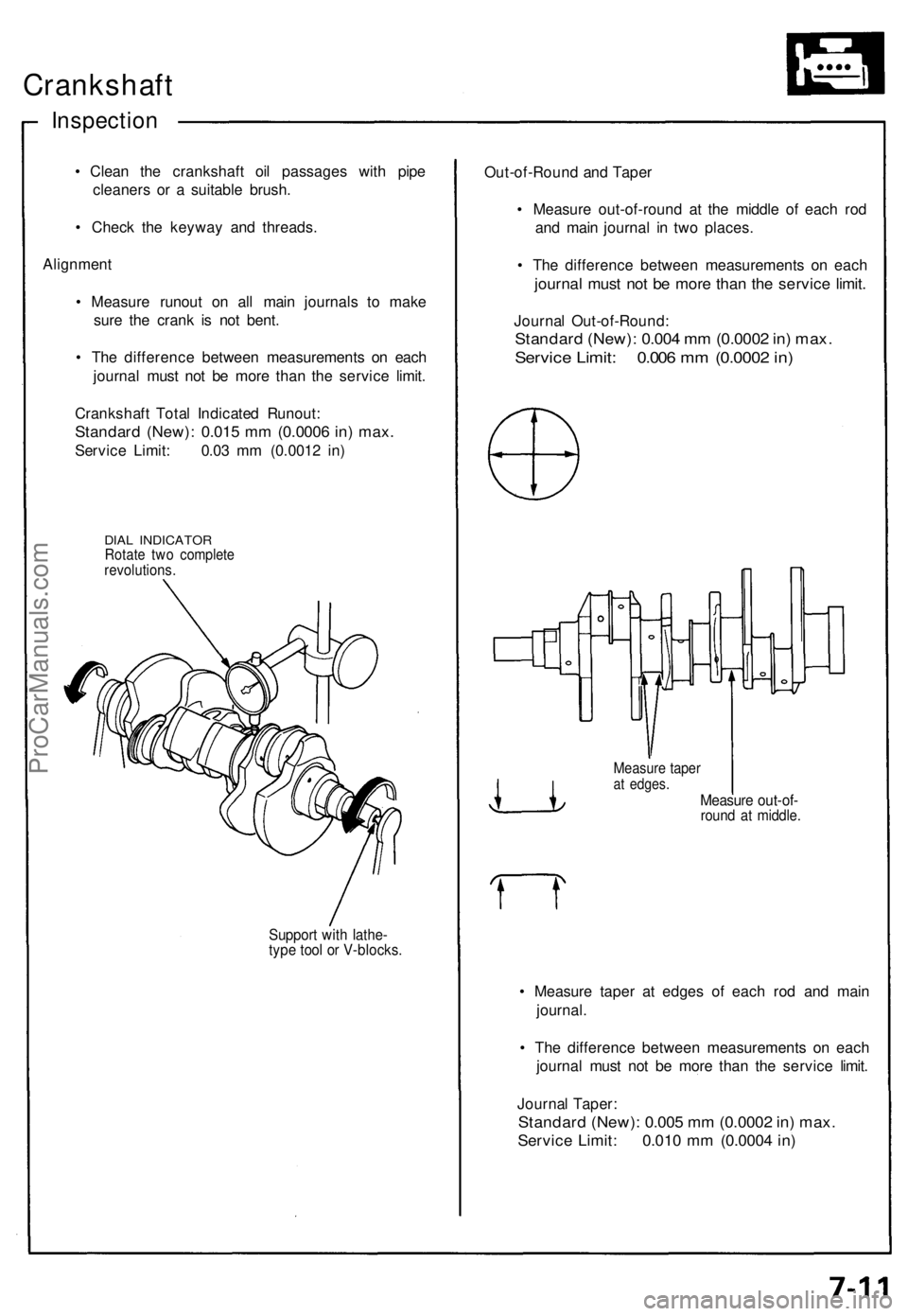
• Measur e runou t o n al l mai n journal s t o mak e
sur e th e cran k i s no t bent .
• Th e differenc e betwee n measurement s o n eac h
journa l mus t no t b e mor e tha n th e servic e limit .
Crankshaf t Tota l Indicate d Runout :
Standard (New) : 0.01 5 m m (0.000 6 in ) max .
Servic e Limit : 0.0 3 m m (0.001 2 in )
DIA L INDICATO RRotate tw o complet erevolutions .
Support wit h lathe -type too l o r V-blocks .
Out-of-Roun d an d Tape r
• Measur e out-of-roun d a t th e middl e o f eac h ro d
an d mai n journa l i n tw o places .
• Th e differenc e betwee n measurement s o n eac h
journa l mus t no t b e mor e tha n th e servic e limit .
Journa l Out-of-Round :
Standard (New) : 0.00 4 m m (0.000 2 in ) max .
Servic e Limit : 0.00 6 m m (0.000 2 in )
Measur e tape rat edges .Measur e out-of -round a t middle .
• Measur e tape r a t edge s o f eac h ro d an d mai n
journal .
• Th e differenc e betwee n measurement s o n eac h
journa l mus t no t b e mor e tha n th e servic e limit .
Journa l Taper :
Standar d (New) : 0.00 5 m m (0.000 2 in ) max .
Servic e Limit : 0.01 0 m m (0.000 4 in )
ProCarManuals.com
Page 437 of 1640
Steering Gearbox
Removal/Installation
NOTE: Before removing the steering gearbox, make
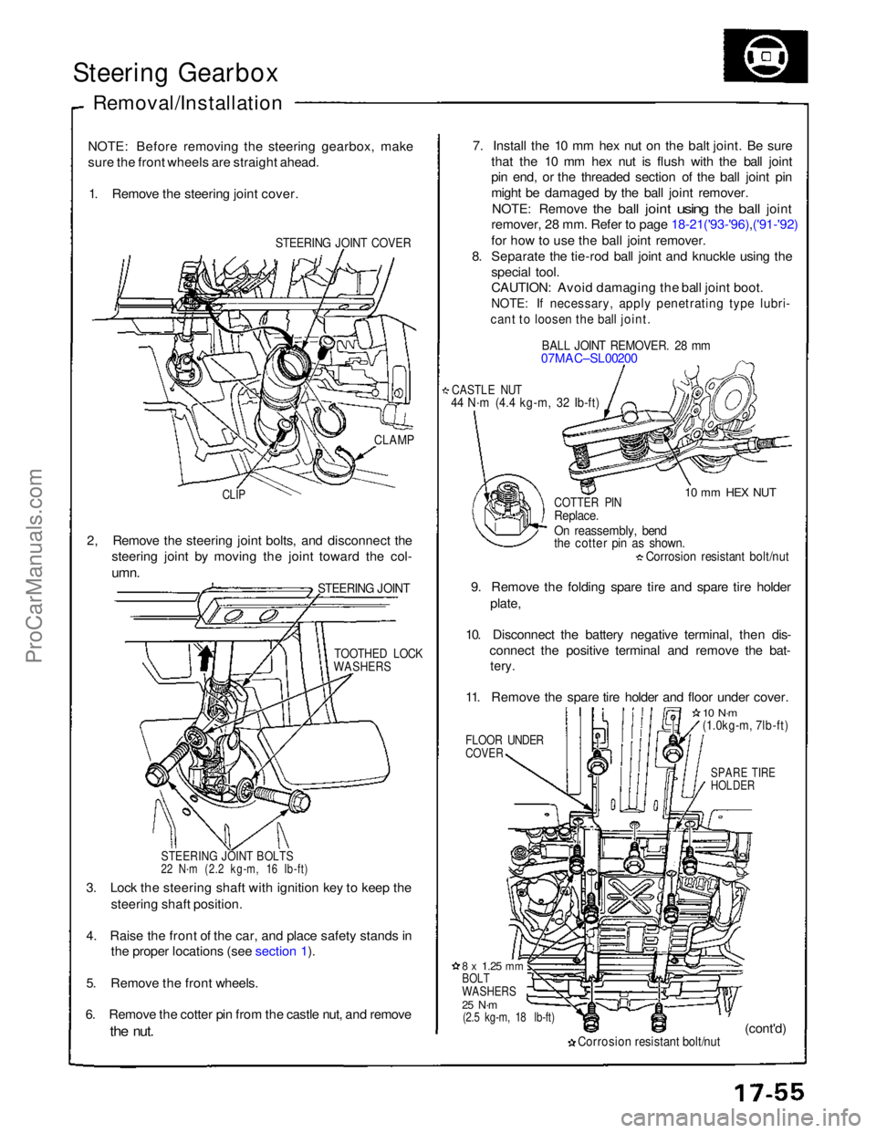
sure the front wheels are straight ahead. 1. Remove the steering joint cover.
STEERING JOINT COVER
7. Install the 10 mm hex nut on the balt joint. Be sure
that the 10 mm hex nut is flush with the ball joint
pin end, or the threaded section of the ball joint pin
might be damaged by the ball joint remover.
NOTE: Remove
the
ball
joint
using
the
ball
joint
remover, 28 mm. Refer to page 18-21('93-'96),('91-'92)
for how to use the ball joint remover.
8. Separate the tie-rod ball joint and knuckle using the
special tool.
CAUTION: Avoid damaging the ball joint boot.
NOTE: If necessary, apply penetrating type lubri-
cant to loosen the ball joint.
BALL JOINT REMOVER. 28 mm
07MAC–SL00200
CASTLE NUT
44 N·m (4.4 kg-m, 32 Ib-ft)
10 mm HEX NUT
CLAMP
CLIP
COTTER PIN
Replace.
On reassembly, bend
the cotter pin as shown.
Corrosion resistant bolt/nut
9. Remove the folding spare tire and spare tire holder plate,
10. Disconnect the battery negative terminal, then dis- connect the positive terminal and remove the bat-
tery.
11. Remove the spare tire holder and floor under cover.
FLOOR UNDER
COVER
10 N·m
(1.0kg-m, 7lb-ft)
SPARE TIRE
HOLDER
2, Remove the steering joint bolts, and disconnect the
steering joint by moving the joint toward the col-
umn.
STEERING JOINT
TOOTHED LOCK
WASHERS
STEERING JOINT BOLTS
22 N·m (2.2 kg-m, 16 Ib-ft)
3. Lock the steering shaft with ignition key to keep the steering shaft position.
4. Raise the front of the car, and place safety stands in the proper locations (see section 1).
5. Remove the front wheels.
6. Remove the cotter pin from the castle nut, and remove
the
nut.
8 x
1.25
mm
BOLT
WASHERS
25 N·m
(2.5 kg-m, 18 lb-ft)
Corrosion resistant bolt/nut
(cont'd)ProCarManuals.com
Page 531 of 1640
Diagnostic Trouble Code (DTC):
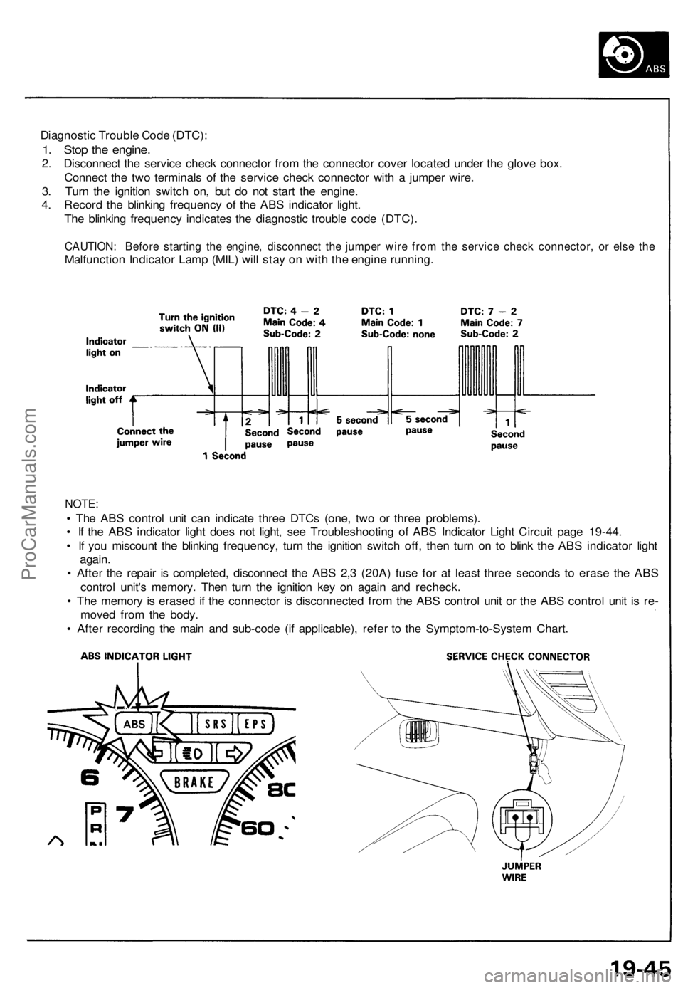
1. Stop the engine.
2. Disconnect the service check connector from the connector cover located under the glove box.
Connect the two terminals of the service check connector with a jumper wire.
3. Turn the ignition switch on, but do not start the engine.
4. Record the blinking frequency of the ABS indicator light.
The blinking frequency indicates the diagnostic trouble code (DTC).
CAUTION: Before starting the engine, disconnect the jumper wire from the service check connector, or else the
Malfunction Indicator Lamp (MIL) will stay on with the engine running.
NOTE:
• The ABS control unit can indicate three DTCs (one, two or three problems).
• If the ABS indicator light does not light, see Troubleshooting of ABS Indicator Light Circuit page 19-44.
• If you miscount the blinking frequency, turn the ignition switch off, then turn on to blink the ABS indicator light
again.
• After the repair is completed, disconnect the ABS 2,3 (20A) fuse for at least three seconds to erase the ABS
control unit's memory. Then turn the ignition key on again and recheck.
• The memory is erased if the connector is disconnected from the ABS control unit or the ABS control unit is re-
moved from the body.
• After recording the main and sub-code (if applicable), refer to the Symptom-to-System Chart.ProCarManuals.com
Page 731 of 1640
Five-step Troubleshooting
1. Verify The Complaint
Turn on all the components in the problem circuit to
verify the customer complaint. Note the symp-
toms. Do not begin disassembly or testing until you
have narrowed down the problem area.
2. Analyze The Schematic
Look up the schematic for the problem circuit.
Determine how the circuit is supposed to work by
tracing the current paths from the power feed
through the circuit components to ground. If
several circuits fail at the same time, the fuse or
ground is a likely cause.
Based on the symptoms and your understanding of
the circuit operation, identify one or more possible
causes of the problem.
3. Isolate The Problem By Testing The Circuit
Make circuit tests to check the diagnosis you made
in step 2. Keep in mind that a logical, simple pro-
cedure is the key to efficient troubleshooting. Test
for the most likely cause of failure first. Try to make
tests at points that are easily accessible.
4. Fix The Problem
Once the specific problem is identified, make the
repair. Be sure to use proper tools and safe
procedures.
5. Make Sure The Circuit Works
Turn on all components in the repaired circuit in all
modes to make sure you've fixed the entire pro-
blem. If the problem was a blown fuse, be sure to
test all of the circuits on that fuse. Make sure no
new problems turn up and the original problem
does not recur.ProCarManuals.com
Page 743 of 1640
Ignition Switc h
Test
1. Remov e th e dashboar d lowe r cove r (se e nex t
column) .
2 . Disconnec t th e 7- P connecto r fro m th e floo r wir e
harness .
3. Chec k fo r continuit y betwee n th e terminal s in eac h
switc h positio n accordin g t o th e table.
WHT (BAT-A )
BLU/WH T (IG2-B ) Vie
w fro m
wir e sid e
BLK/WH T (ST )
WHT/BL K (BAT-B )
WHT/RE D (ACC )
Electrica l Switc h Replacemen t
1. Remov e th e dashboar d lowe r cove r an d disconnec t
th e floo r wir e harnes s connectors .
DASHBOAR D
LOWE R
COVE R
2. Disconnec t th e 7- P connecto r fro m th e floo r wir e
harness .
3. Inser t th e key , an d tur n it t o "0" .
4. Remov e th e tw o screws , an d replac e th e switch .
LOCK CYLINDE R
SWITC H
WHT
(IG2-A ) 7-
P CONNECTO R
BLK/YEL (IG1)
ProCarManuals.com
Page 745 of 1640
Ignition Switch
Steering Lock Removal/Installation
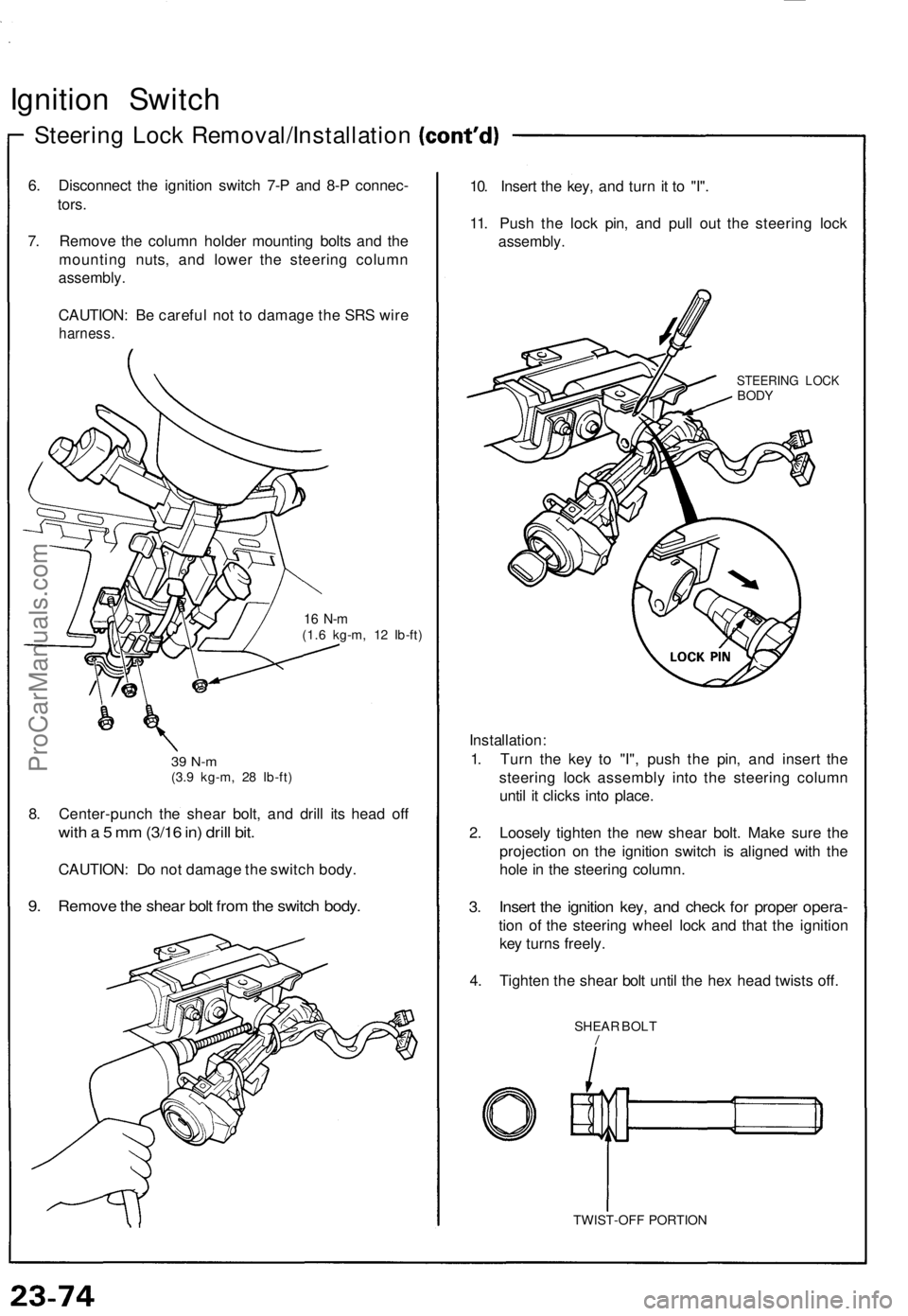
6. Disconnect the ignition switch 7-P and 8-P connec-
tors.
7. Remove the column holder mounting bolts and the
mounting nuts, and lower the steering column
assembly.
CAUTION: Be careful not to damage the SRS wire
harness.
16 N-m
(1.6 kg-m, 12 Ib-ft)
39 N-m
(3.9 kg-m, 28 Ib-ft)
8. Center-punch the shear bolt, and drill its head off
with a 5 mm (3/16 in) drill bit.
CAUTION: Do not damage the switch body.
9. Remove the shear bolt from the switch body.
10. Insert the key, and turn it to "I".
11. Push the lock pin, and pull out the steering lock
assembly.
STEERING LOCK
BODY
Installation:
1. Turn the key to "I", push the pin, and insert the
steering lock assembly into the steering column
until it clicks into place.
2. Loosely tighten the new shear bolt. Make sure the
projection on the ignition switch is aligned with the
hole in the steering column.
3. Insert the ignition key, and check for proper opera-
tion of the steering wheel lock and that the ignition
key turns freely.
4. Tighten the shear bolt until the hex head twists off.
SHEAR BOLT
/
TWIST-OFF PORTIONProCarManuals.com