Page 947 of 1640
Security Alar m Syste m
Descriptio n
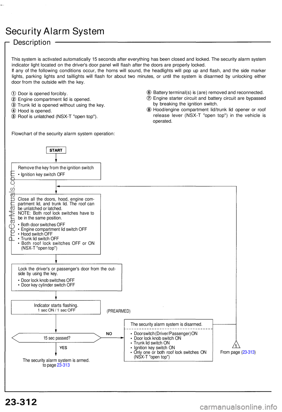
This syste m is activate d automaticall y 1 5 second s afte r everythin g ha s bee n close d an d locked . Th e securit y alar m syste m
indicato r ligh t locate d o n th e driver' s doo r pane l wil l flas h afte r th e door s ar e properl y locked .
I f an y o f th e followin g condition s occur , th e horn s wil l sound , th e headlight s wil l po p u p an d flash , an d th e sid e marke r
lights , parkin g light s an d taillight s wil l flas h fo r abou t tw o minutes , o r unti l th e syste m is disarme d b y unlockin g eithe r
doo r fro m th e outsid e wit h th e key .
Doo r i s opene d forcibly .
Engin e compartmen t li d i s opened .
Trun k li d i s opene d withou t usin g th e key .
Hoo d is opened .
Roof i s unlatche d (NSX- T "ope n top") .
Flowchar t o f th e securit y alar m syste m operation : Batter
y terminal(s ) i s (are ) remove d an d reconnected .
Engin e starte r circui t an d batter y circui t ar e bypasse d
b y breakin g th e ignitio n switch .
Hood/engin e compartmen t lid/trun k li d opene r o r roo f
releas e leve r (NSX- T "ope n top" ) i n th e vehicl e i s
operated .
Remove th e ke y fro m th e ignitio n switc h
• Ignitio n ke y switc h OF F
Clos e al l th e doors , hood , engin e com -
partmen t lid , an d trun k lid . Th e roo f ca n
b e unlatche d o r latched .
NOTE : Bot h roo f loc k switche s hav e t o
b e in th e sam e position .
• Bot h doo r switche s OF F
• Engin e compartmen t li d switc h OF F
• Hoo d switc h OF F
• Trun k li d switc h OF F
• Bot h roo f loc k switche s OF F o r O N
(NSX- T "ope n top" )
Loc k th e driver' s o r passenger' s doo r fro m th e out -
sid e b y usin g th e key .
• Doo r loc k kno b switche s OF F
• Doo r ke y cylinde r switc h OF F
(PREARMED )
15 se c passed ?
The securit y alar m syste m is armed .
t o pag e 23-31 3 Th
e securit y alar m syste m is disarmed .
Doo r switc h (Driver/Passenger ) O N
Doo r loc k kno b switc h O N
Trun k li d switc h O N
Ignitio n ke y switc h O N
Onl y on e o r bot h roo f loc k switche s O N
(NSX- T "ope n top" ) Fro
m pag e ( 23-313 )
Indicato
r start s flashing .
1 se c O N / 1 se c OF F
ProCarManuals.com
Page 948 of 1640
From pag e 23-31 2
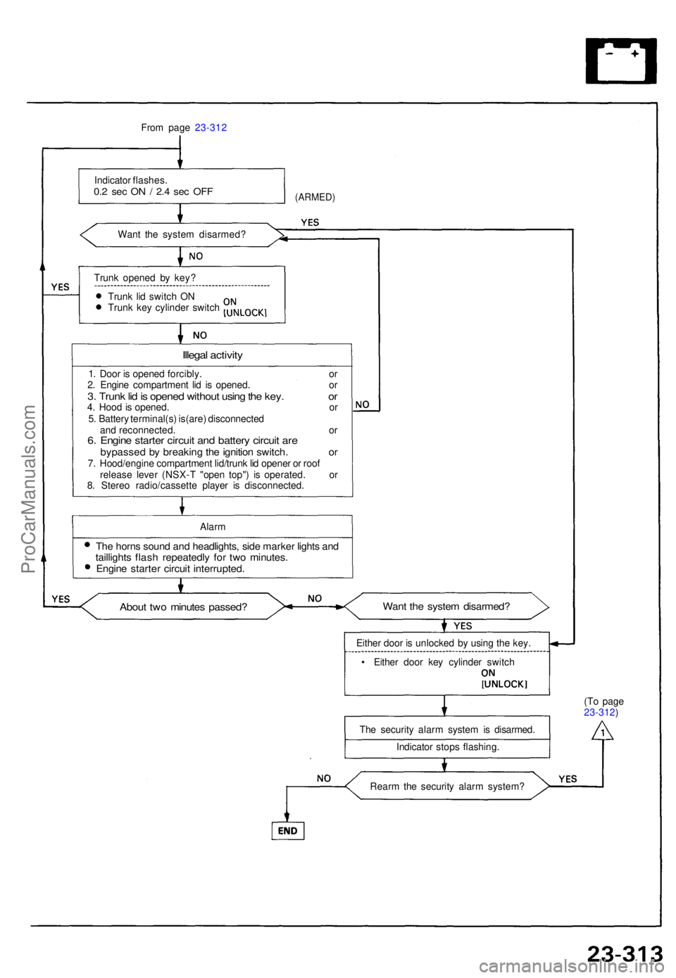
Indicato r flashes .
0.2 se c O N / 2. 4 se c OF F
Wan t th e syste m disarmed ?
(ARMED)
Trunk opene d b y key ?
Trun k li d switc h O N
Trun k ke y cylinde r switc h
Illegal activit y
1. Doo r i s opene d forcibly . o r
2 . Engin e compartmen t li d i s opened . o r
3. Trun k li d is opene d withou t usin g th e key . o r4. Hoo d is opened . o r
5 . Batter y terminal(s ) is(are ) disconnecte d
an d reconnected . o r
6. Engin e starte r circui t an d batter y circui t ar ebypasse d b y breakin g th e ignitio n switch . o r7. Hood/engin e compartmen t lid/trun k li d opene r o r roo f
releas e leve r (NSX- T "ope n top" ) i s operated . o r
8 . Stere o radio/cassett e playe r i s disconnected .
Alar m
The horn s soun d an d headlights , sid e marke r light s an dtaillight s flas h repeatedl y fo r tw o minutes .Engine starte r circui t interrupted .
About tw o minute s passed ?Want th e syste m disarmed ?
Either doo r i s unlocke d b y usin g th e key .
• Eithe r doo r ke y cylinde r switc h
Th e securit y alar m syste m is disarmed .
Indicato r stop s flashing . (T
o pag e
23-312 )
Rear m th e securit y alar m system ?
ProCarManuals.com
Page 955 of 1640
Security Alar m Syste m
Indicato r Replacemen t
1. Remov e th e doo r pane l (se e sectio n 20 ).
2 . Remov e th e tw o screw s fro m th e indicator .
3 . Remov e th e indicato r fro m th e doo r panel .
5-P CONNECTO RINDICATO
R
DOOR PANE L
Trunk Ke y Cylinde r Switc h Tes t
1. Ope n th e trun k li d an d remov e th e trun k rea r panel .
2 . Disconnec t th e 2- P connecto r fro m th e trun k ke y
cylinde r switch .
3 . Chec k continuit y a t th e switc h connecto r terminals .
• Ther e shoul d b e continuit y betwee n th e terminal s
whe n th e trun k loc k i s turne d t o UNLOC K wit h
the key .
• Ther e shoul d b e n o continuit y whe n th e loc k i s
released .
TRUNK KE Y
CYLINDE R SWITC H
2-PCONNECTO RTRUN
K KE Y
CYLINDE R
ProCarManuals.com
Page 1002 of 1640
Cylinder Head/Valve Train
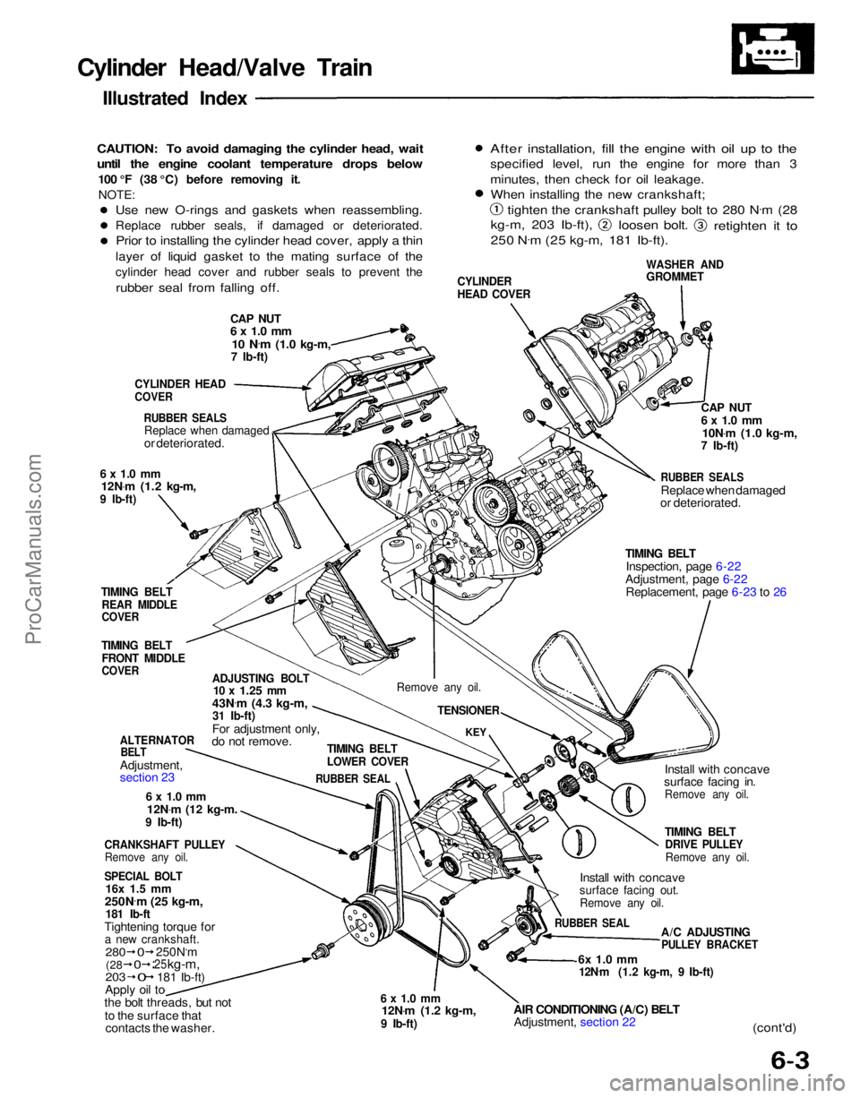
Illustrated Index
CAUTION: To avoid damaging the cylinder head, wait
until the engine coolant temperature drops below
100 °F (38 °C) before removing it.NOTE:
CAP NUT
6 x 1.0 mm
10 N .
m
(1.0 kg-m,
7 Ib-ft)
CYLINDER
HEAD COVER
WASHER AND
GROMMET
After installation, fill the engine with oil up to the
specified level, run the engine for more than 3
minutes, then check for oil leakage.
When installing the new crankshaft;
tighten the crankshaft pulley bolt to 280 N .
m (28
kg-m, 203 Ib-ft),
loosen bolt.
retighten it to
250 N .
m (25 kg-m, 181 Ib-ft).
CYLINDER HEAD
COVER
RUBBER SEALS
Replace when damaged
or deteriorated.
6 x 1.0 mm
12N .
m (1.2 kg-m,
9 Ib-ft)
TIMING BELT
REAR MIDDLE
COVER
TIMING BELT
FRONT MIDDLE
COVER
ADJUSTING BOLT
10 x
1.25
mm
43N .
m (4.3 kg-m,
31 Ib-ft)
For adjustment only,
do not remove.
ALTERNATOR
BELT
Adjustment,
section 23
6 x 1.0 mm
12N .
m
(12
kg-m.
9 Ib-ft)
CRANKSHAFT PULLEY
Remove any oil.
SPECIAL BOLT
16x 1.5 mm
250N .
m (25 kg-m,
181 Ib-ft
Tightening torque for
a new crankshaft.
203
Apply oil to
the bolt threads, but not
to the surface that contacts the washer.
6 x 1.0 mm
12N .
m (1.2 kg-m,
9 Ib-ft)
AIR CONDITIONING (A/C) BELT
Adjustment, section 22
6x 1.0 mm
12N .
m (1.2 kg-m, 9 Ib-ft)
(cont'd)
A/C ADJUSTING
PULLEY BRACKET
RUBBER SEAL
Install with concave
surface facing out.
Remove any oil.
TIMING BELT
DRIVE PULLEY
Remove any oil.
Install with concave
surface facing in.
Remove any oil.
TIMING BELT
Inspection, page 6-22
Adjustment, page 6-22 Replacement, page 6-23 to 26
RUBBER SEALS
Replace when damaged
or deteriorated.
CAP NUT
6 x 1.0 mm
10N .
m (1.0 kg-m,
7 Ib-ft)
TIMING BELT
LOWER COVER
RUBBER SEAL
KEY
Remove any oil.
TENSIONER
280
250N.m
25
kg-m,
181 Ib-ft)
(28
0
0
0
Use new O-rings and gaskets when reassembling.
Replace rubber seals, if damaged or deteriorated.
Prior to installing the cylinder head cover, apply a thin
layer of liquid gasket to the mating surface of the
cylinder head cover and rubber seals to prevent the
rubber seal from falling off.ProCarManuals.com
Page 1011 of 1640
Installation
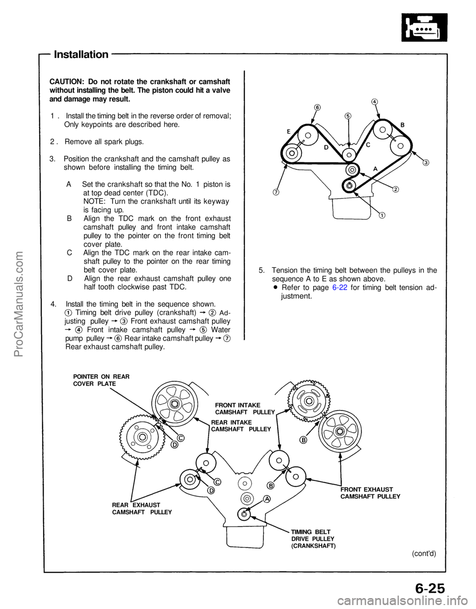
CAUTION: Do not rotate the crankshaft or camshaft without installing the belt. The piston could hit a valve
and damage may result.
1 . Install the timing belt in the reverse order of removal; Only keypoints are described here.
2 . Remove all spark plugs.
3. Position the crankshaft and the camshaft pulley as shown before installing the timing belt.
A Set the crankshaft so that the No. 1 piston is at top dead center (TDC).NOTE: Turn the crankshaft until its keyway
is facing up.
B Align the TDC mark on the front exhaust camshaft pulley and front intake camshaftpulley to the pointer on the front timing belt
cover plate.
C Align the TDC mark on the rear intake cam-
shaft pulley to the pointer on the rear timing
belt cover plate.
D Align the rear exhaust camshaft pulley one half tooth clockwise past TDC.
POINTER ON REAR
COVER PLATE
REAR EXHAUSTCAMSHAFT PULLEY
TIMING BELT
DRIVE PULLEY
(CRANKSHAFT)
FRONT EXHAUST
CAMSHAFT PULLEY
(cont'd)
5. Tension the timing belt between the pulleys in the
sequence A to E as shown above.
4. Install the timing belt in the sequence shown.
FRONT INTAKE
CAMSHAFT PULLEY
REAR INTAKE
CAMSHAFT PULLEY
Rear exhaust camshaft pulley.
Timing belt drive pulley (crankshaft)
Ad-
Water
justing pulley
Front intake camshaft pulley Front exhaust camshaft pulley
pump pulley Rear intake camshaft pulley Refer to page 6-22 for timing belt tension ad-
justment.ProCarManuals.com
Page 1037 of 1640
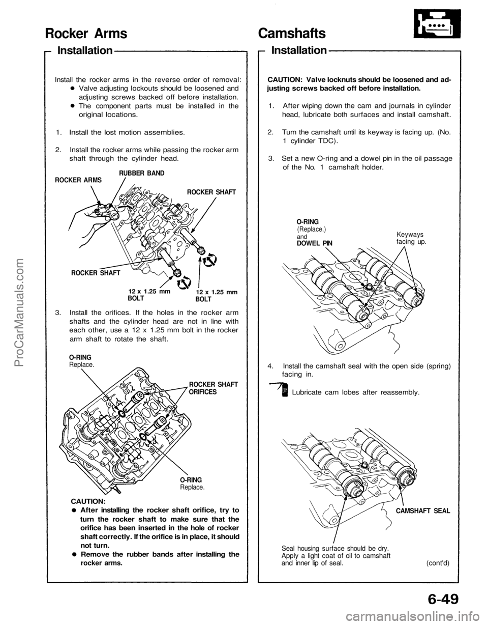
Camshafts
Installation
CAUTION: Valve locknuts should be loosened and ad-
justing screws backed off before installation.
1. After wiping down the cam and journals in cylinder
head, lubricate both surfaces and install camshaft.
2. Turn the camshaft until its keyway is facing up. (No.
1 cylinder TDC).
3. Set a new O-ring and a dowel pin in the oil passage
of the No. 1 camshaft holder.
O-RING
(Replace.)
and
DOWEL PIN
Keyways
facing up.
4. Install the camshaft seal with the open side (spring)
facing in.
Lubricate cam lobes after reassembly.
CAMSHAFT SEAL
Seal housing surface should be dry.
Apply a light coat of oil to camshaft
and inner lip of seal. (cont'd)
After installing the rocker shaft orifice, try to
turn the rocker shaft to make sure that the
orifice has been inserted in the hole of rocker
shaft correctly. If the orifice is in place, it should
not turn.
Remove the rubber bands after installing the
rocker arms.
O-RING
Replace.
ROCKER SHAFT
ORIFICES
O-RING
Replace.
3. Install the orifices. If the holes in the rocker arm
shafts and the cylinder head are not in line with
each other, use a 12 x 1.25 mm bolt in the rocker
arm shaft to rotate the shaft.
ROCKER SHAFT
12 x
1.25
mm
BOLT
12 x
1.25
mm
BOLT
ROCKER SHAFT
ROCKER ARMS
RUBBER BAND
1. Install the lost motion assemblies.
2. Install the rocker arms while passing the rocker arm
shaft through the cylinder head.
Rocker Arms
Installation
Valve adjusting lockouts should be loosened and
adjusting screws backed off before installation.
The component parts must be installed in the
original locations.
Install the rocker arms in the reverse order of removal:
CAUTION:ProCarManuals.com
Page 1292 of 1640
Gearshift Selector
All SRS wiring harnesses are covered with yellow
outer insulation.
Before disconnecting any part of the SRS wire
harness, install the short connectors (see page
23-328).
Replace the entire affected SRS harness assembly if
it has an open circuit or damaged wiring.
CAUTION:
SELECT LEVER KNOB
3 N.
m
(0.3 kg-m, 2 Ib-ft)
SRS MAIN
HARNESS
SILICONE GREASE
3 N .
m
(0.3 kg-m, 2 Ib-ft)
Apply non hardening
thread lock sealant.
SHIFT INDICATOR PANEL
KEY CYLINDER
3 N .
m
(0.3 kg-m, 2 Ib-ft)
5 N.
m (0.5 kg-m, 4 Ib-ft)
A/T GEAR
POSITION
SWITCH
SILICONE
GREASE
LEVER COVER
SHIFT INDICATOR
3 N .
m (0.3 kg-m, 2 Ib-ft)
SHIFT CABLE
SILICONE GREASE
10 N.
m
(1.0 kg-m, 7 Ib-ft)
SHIFT LOCK
SOLENOID
E-CLIP
3 N .
m
(0.3 kg-m, 2 Ib-ft)
DETENT COVER
DETENT
PLATE
10 N
.
m (1.0 kg-m, 7 Ib-ft)
BRACKET BEAM
SHIFT CABLE HOLDER
Install in this direction.
CONTROL
LEVER PIN
LOCK PIN
SELECTOR MOUNT
BRACKET
SILICONE
GREASEProCarManuals.com
Page 1311 of 1640
Component Location
Index
NOTE:
If an intact airbag assembly has been removed from a scrapped car or has been found defective or damaged during
transit, storage or service, it should be deployed (see section 23). Before removing the gearbox, remove the ignition key to lock the steering shaft from turning.
After installing the gearbox, check the wheel alignment and adjust if necessary.
STEERING WHEEL/AIRBAG ASSEMBLY
Removal, page 17-8
Disassembly, page 17-9
Installation, page 17-10
STEERING COLUMN
Removal, page 17-12
Inspection, page 17-14 Installation, page 17-15
STEERING GEARBOX
Removal/Installation, page 17-19 Disassembly, page 17-22
Inspection, page 17-21
Reassembly, page 17-25ProCarManuals.com