1991 ACURA NSX tire pressure
[x] Cancel search: tire pressurePage 451 of 1640
Wheel Alignment
Height
NSX/NSX-T four wheel alignment requires the use of equipment designed specifically for four wheel independent
suspensions and capable of immediate feedback.
NOTE: For proper inspection/adjustment of the wheel alignment, check and adjust the following before checking
the alignment.
• Check that the suspension is not modified.
• Check the tire size and tire pressure.
• Check the runout of the wheels and tires.
• Check the suspension ball joints. (Hold a wheel with your hands, then move the wheel up and down and right
and left to check for wobbling.)
• Check the height of each suspension (see below).
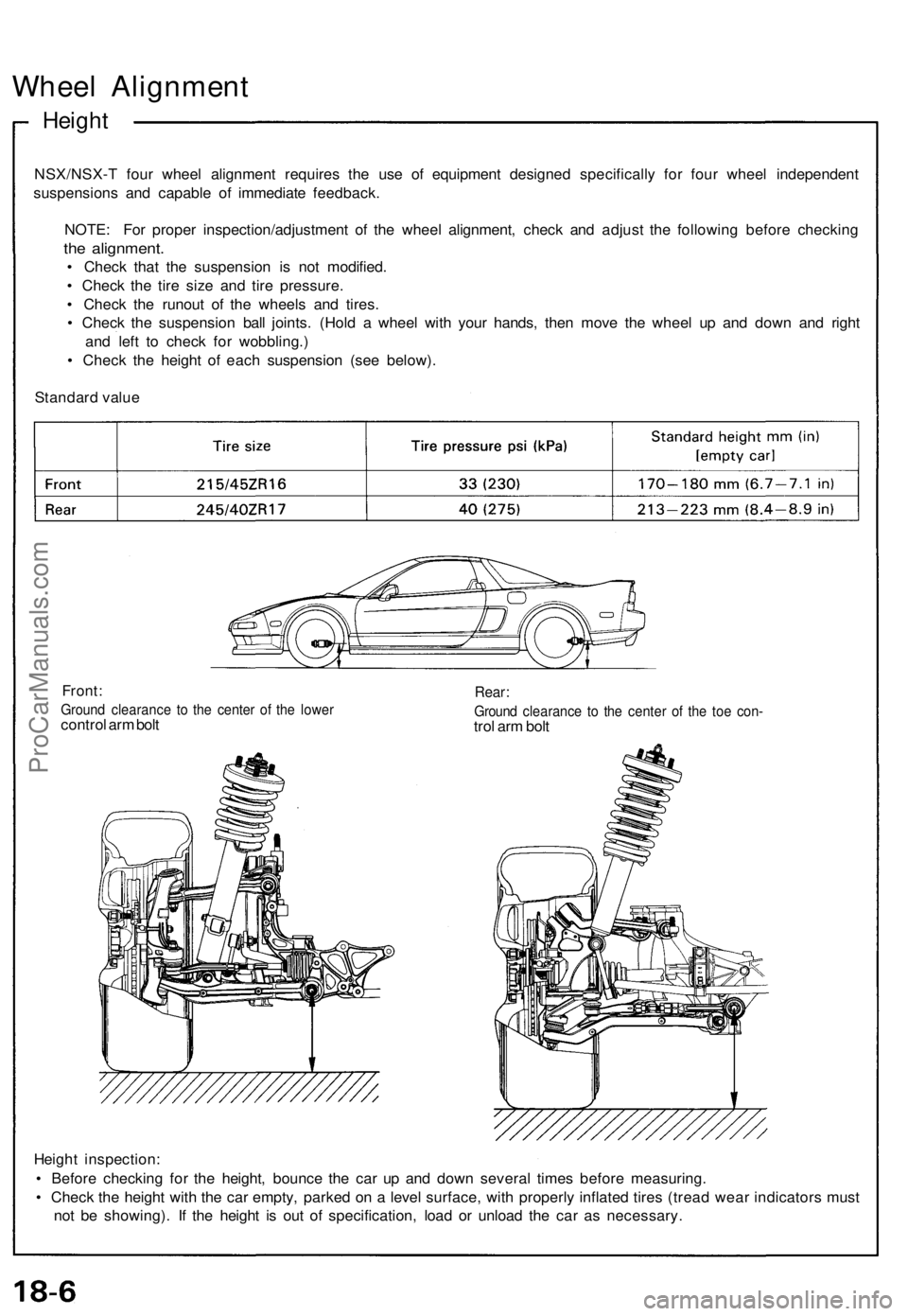
Standard value
Front:
Ground clearance to the center of the lower
control arm bolt
Rear:
Ground clearance to the center of the toe con-
trol arm bolt
Height inspection:
• Before checking for the height, bounce the car up and down several times before measuring.
• Check the height with the car empty, parked on a level surface, with properly inflated tires (tread wear indicators must
not be showing). If the height is out of specification, load or unload the car as necessary.ProCarManuals.com
Page 452 of 1640
Front Wheel Alignment Adjusting Procedure
Adjustment
NOTE: NSX/NSX-T four wheel alignment requires the use of equipment designed specifically for four wheel independent
suspensions and capable of immediate feedback.
The NSX/NSX-T suspension can be adjusted for camber, caster (front only), and toe. However, because each of them
relates to the other, the camber changes when the toe is adjusted for example. Therefore, the total adjustment of the
front/rear wheel alignment is required whenever one of the elements (camber, caster, or toe) is adjusted.
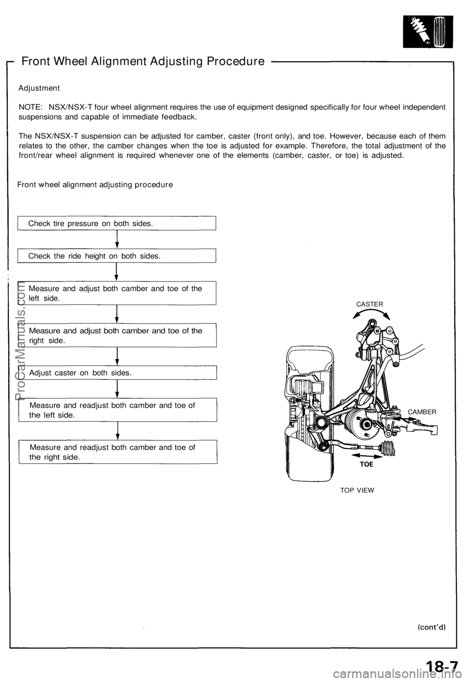
Front wheel alignment adjusting procedure
Check tire pressure on both sides.
Check the ride height on both sides.
Measure and adjust both camber and toe of the
left side.
Measure and adjust both camber and toe of the
right side.
Adjust caster on both sides.
Measure and readjust both camber and toe of
the left side.
Measure and readjust both camber and toe of
the right side.
CASTER
TOP VIEW
CAMBERProCarManuals.com
Page 1165 of 1640
Description
The automatic transmission is a combination of a 3-element torque converter and a triple-shaft electronically controlled
automatic transmission which provides 4 speeds forward and 1 in reverse. The entire unit is positioned in line with the
engine.
TORQUE CONVERTER, GEARS AND CLUTCHES
The torque converter consists of a pump, turbine and stator, assembled in a single unit.
They are connected to the engine crankshaft so they turn together as a unit as the engine turns.
Around the outside of the torque converter is a ring gear which meshes with the starter pinion when the engine is being
started. The entire torque converter assembly serves as a flywheel while transmitting power to the transmission mainshaft.
The transmission has three parallel shafts, the mainshaft, the countershaft, and the secondary shaft. The mainshaft is
in line with the engine crankshaft.
The mainshaft includes the clutches for 1st, and 4th, and gears for 3rd, 4th, Reverse and 1st (3rd gear is integral with
the mainshaft, while reverse gear is integral with 4th gear).
The countershaft includes the clutches for 1st-Hold and 3rd, and gears for 2nd, 3rd, 4th, Reverse and 1st.
The secondary shaft includes the 2nd clutch and gears for 2nd and 3rd.
The 4th and reverse gears can be locked to the countershaft at its center, providing 4th gear or Reverse, depending on
which way the selector is moved.
The gears on the mainshaft and secondary shaft are in constant mesh with those on the countershaft.
When certain combinations of gears in the transmission are engaged by clutches, power is transmitted from the main-
shaft to the countershaft to provide , , , and
ELECTRONIC CONTROL
The electronic control system consists of the Transmission Control Module (TCM), sensors, a linear solenoid and 4
solenoid valves. Shifting and lock-up are electronically controlled for comfortable driving under all conditions.
The TCM is located on the insulator center bulkhead, behind the driver's seat.
HYDRAULIC CONTROL
The valve bodies include the main valve body, secondary valve body, servo body, regulator valve body, throttle valve
body, lock-up valve body and the 2nd accumulator body.
They are bolted to the torque converter housing as an assembly.
The main valve body contains the manual valve, 1-2 shift valve, 2-3 shift valve, 3-4 shift valve, relief valve, one-way
relief valve and oil pump gears.
The secondary valve body contains the 3-2 kick-down valve, CPC (clutch pressure control) valve, 2nd orifice control
valve, 3rd orifice control valve, modulator valve, 4th exhaust valve, servo control valve, 2nd exhaust valve and 4-3 kick-
down valve.
The servo body contains the accumulator pistons and servo valve. The throttle valve body includes the throttle valve B
which is bolted onto the servo body.
The regulator valve body contains the pressure regulator valve, lock-up control valve and cooler relief valve. Fluid from
the regulator passes through the manual valve to the various control valves.
The lock-up valve body contains the lock-up timing B valve and lock-up shift valve. The 2nd accumulator body contains
the accumulator pistons and limited slip differential (LSD) relief valve.
The torque converter check valve is located in the torque converter housing, under the main valve body.
The 1st, 1st-hold, 3rd and 4th clutches receive oil from their respective feed pipes.
SHIFT CONTROL MECHANISM
Input from various sensors located throughout the car determines which shift control solenoid valve the TCM will ac-
tivate. Activating a shift control solenoid valve changes modulator pressure, causing a shift valve to move. This
pressurizes a line to one of the clutches, engaging that clutch and its corresponding gear.
LOCK-UP MECHANISM
In position and position in 2nd, 3rd and 4th, pressurized fluid is drained from the back of the torque converter
through an oil passage, causing the lock-up piston to be held, against the torque converter cover. As this takes place, the
mainshaft rotates at the same speed as the engine crankshaft. Together with hydraulic control, the TCM optimizes the
timing of the lock-up mechaism.
The lock-up valves control the range of lock-up according to lock-up control solenoid valves A and B, and throttle valve B.
When lock-up control solenoid valves A and B activate, modulator pressure changes. The lock-up control solenoid valves
A and B are mounted on the torque converter housing, and are controlled by the TCM.
(cont'd)ProCarManuals.com
Page 1365 of 1640
Troubleshooting
TCS Indicator Light
Temporary Driving Conditions:
1. The TCS indicator light will come on and the control unit memorizes the Diagnostic Trouble Code (DTC) under cer-
tain temporary conditions:
2. If the TCS indicator light does not come back on after correcting the tire or tire pressure problem, the TCS system is
OK.
NOTE: Remove the ABS 2.3 (20 A) fuse for at least 3 seconds to clear the DTC from the TCS control unit memory.
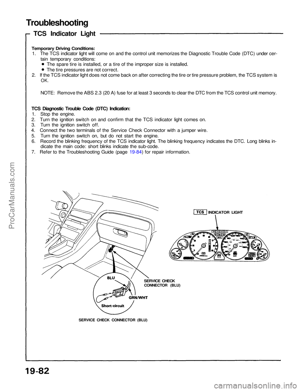
TCS Diagnostic Trouble Code (DTC) Indication: 1. Stop the engine.
2. Turn the ignition switch on and confirm that the TCS indicator light comes on.
3. Turn the ignition switch off.
4. Connect the two terminals of the Service Check Connector with a jumper wire.
5. Turn the ignition switch on, but do not start the engine.6. Record the blinking frequency of the TCS indicator light. The blinking frequency indicates the DTC. Long blinks in- dicate the main code: short blinks indicate the sub-code.
7. Refer to the Troubleshooting Guide (page 19-84) for repair information. The spare tire is installed, or a tire of the improper size is installed.
The tire pressures are not correct.
SERVICE CHECK CONNECTOR (BLU)
SERVICE CHECK
CONNECTOR (BLU)
INDICATOR LIGHTProCarManuals.com
Page 1556 of 1640
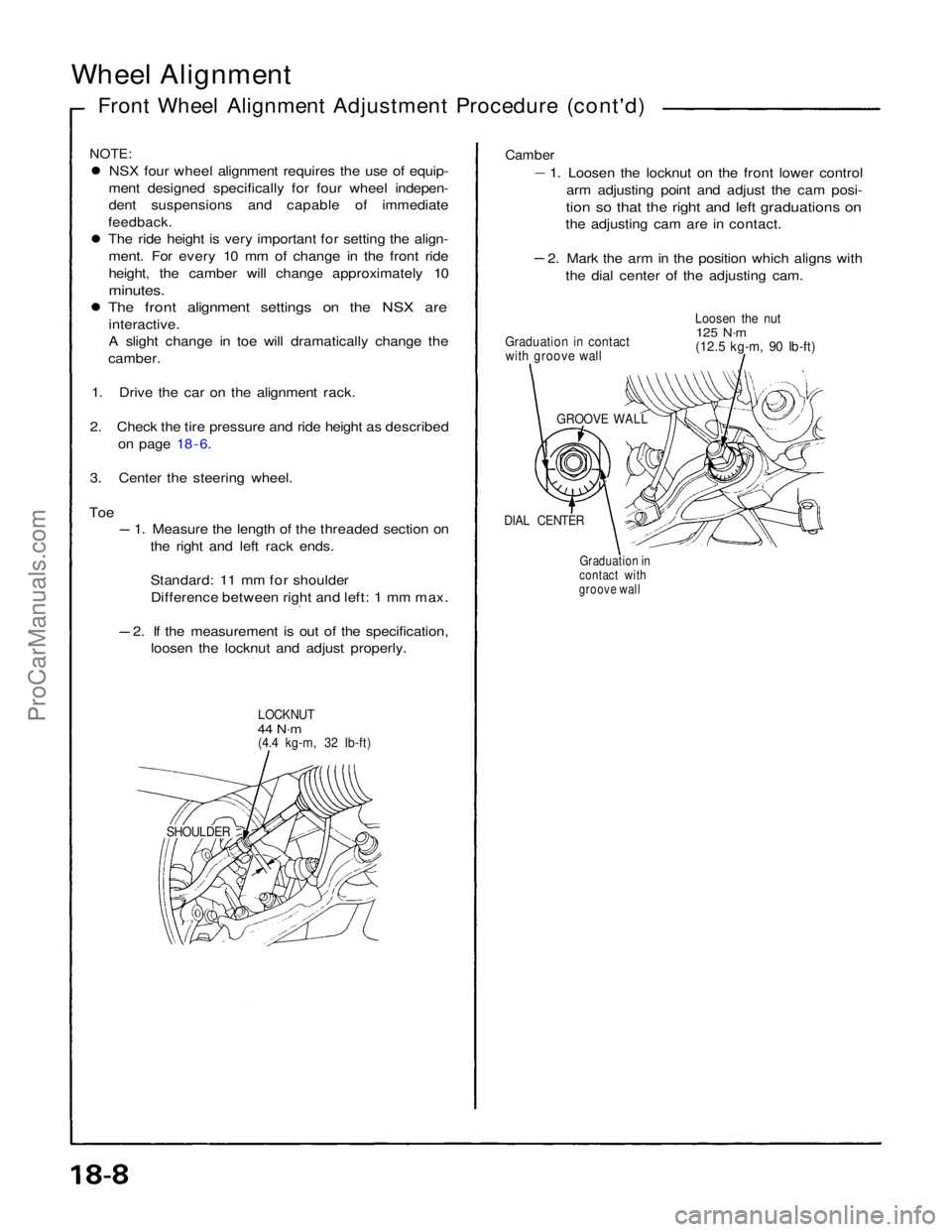
Wheel Alignment
Front Wheel Alignment Adjustment Procedure (cont'd)
NOTE:
NSX four wheel alignment requires the use of equip-
ment designed specifically for four wheel indepen-
dent suspensions and capable of immediate
feedback.
The ride height is very important for setting the align-
ment. For every 10 mm of change in the front ride
height, the camber will change approximately 10
minutes.
The front alignment settings on the NSX are
interactive.
A slight change in toe will dramatically change the
camber.
1. Drive the car on the alignment rack.
2. Check the tire pressure and ride height as described on page 18 - 6.
3. Center the steering wheel.
Toe
1. Measure the length of the threaded section on
the right and left rack ends.
Standard: 11 mm for shoulderDifference between right and left: 1 mm max. 2. If the measurement is out of the specification,
loosen the locknut and adjust properly.
LOCKNUT
44 N·m
(4.4 kg-m, 32 Ib-ft)
SHOULDERGraduation in
contact with
groove wall
DIAL CENTER
GROOVE WALL
Graduation in contact
with groove wall Loosen the nut
125 N·m
(12.5 kg-m, 90 Ib-ft)
Camber
1. Loosen the locknut on the front lower control
arm adjusting point and adjust the cam posi-
tion so that the right and left graduations on
the adjusting cam are in contact. 2. Mark the arm in the position which aligns with
the dial center of the adjusting cam.ProCarManuals.com
Page 1559 of 1640
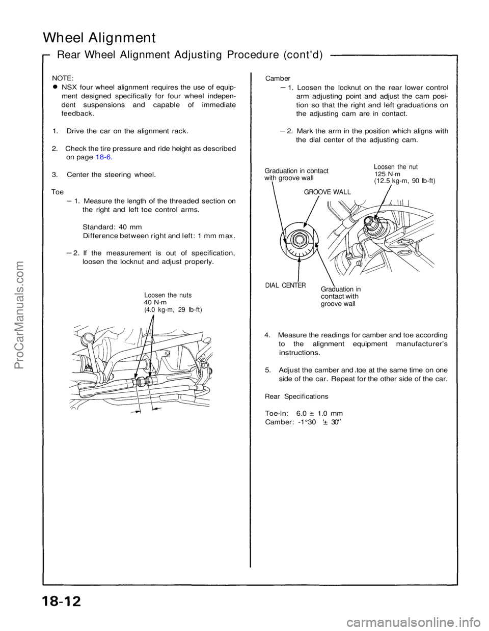
Wheel Alignment
Rear Wheel Alignment Adjusting Procedure (cont'd)
NOTE:
NSX four wheel alignment requires the use of equip-
ment designed specifically for four wheel indepen-
dent suspensions and capable of immediate
feedback.
1. Drive the car on the alignment rack.
2. Check the tire pressure and ride height as described on page 18-6.
3. Center the steering wheel.
Toe
1. Measure the length of the threaded section onthe right and left toe control arms.
Standard: 40 mmDifference between right and left: 1 mm max. 2. If the measurement is out of specification,
loosen the locknut and adjust properly.
Loosen the nuts
40 N·m
(4.0 kg-m, 29 Ib-ft)
Camber
1. Loosen the locknut on the rear lower controlarm adjusting point and adjust the cam posi-
tion so that the right and left graduations on
the adjusting cam are in contact. 2. Mark the arm in the position which aligns with
the dial center of the adjusting cam.
Graduation in contact
with groove wall
Loosen the nut
125 N·m
(12.5 kg-m, 90 Ib-ft)
DIAL CENTER
Graduation in
contact with
groove wall
4. Measure the readings for camber and toe according to the alignment equipment manufacturer's
instructions.
5. Adjust the camber and .toe at the same time on one side of the car. Repeat for the other side of the car.
Rear Specifications
Toe-in: 6.0 1.0 mm
Camber: -1°30 ' 30'
GROOVE WALLProCarManuals.com