Page 208 of 1640
II. Engine Control Module (ECM) Reset Procedure
Either of the following actions, will reset the ECM.
• Using the OBD-II scan tool or Honda PGM Tester to clear the ECM's memory.
NOTE: See the OBD-II scan tool or Honda PGM Tester user's manuals for specific operating instructions.
• Turn the ignition switch OFF. Remove the CLOCK (7.5 A) fuse from the under-hood fuse/relay box for 10 seconds.
UNDER-HOOD
FUSE/RELAY BOX
CLOCK
(7.5 A) FUSE
III. Final Procedure (this procedure must be done after any troubleshooting)
1. Remove the SCS Service Connector if it is connected.
NOTE: If the SCS service connector is connected and there are no DTCs stored in the ECM, the MIL will stay on
when the ignition switch is turned on.
2. Do the ECM Reset Procedure.
3. Turn the ignition switch OFF.
4. Disconnect the OBD-II scan tool or Honda PGM Tester from the Data Link Connector,ProCarManuals.com
Page 358 of 1640

Preset Torqu e
Inspectio n
On-Car:
1 . Bloc k th e fron t wheels .
2 . Shif t t o low gear .
3 . Lif t u p rea r wheels , an d plac e th e safet y stan d (Lif t
an d Suppor t Points , se e sectio n 1 ).
4 . Measur e prese t torqu e clockwis e usin g a torqu e
wrenc h a s shown .
Standard: 120-280 N-m (12-28 kg-m,
87-20 3 Ib-ft )
Servic e Limit : 6 0 N- m (6 kg-m , 4 3 Ib-ft )
TORQU E WRENC H
RIGH T REA R WHEE L
SAFETY STAN D
5. I f prese t torqu e is les s tha n th e servic e limit , replac e
th e limite d sli p differentia l clutc h set .
NOTE : Adjus t th e 6 5 m m (differentia l housin g cove r
side ) an d 11 2 m m (differentia l housin g cove r side )
shim s wheneve r th e clutc h se t i s replaced . Assembly
:
Plac e on e specia l too l i n a vise . Plac e th e lef t sid e
o f th e differentia l assembl y o n th e specia l tool , the n
prese t th e differentia l wit h 3- 5 rotations , counter -
clockwise .
DIFFERENTIA L
INSPECTIO N TOOL S
07MAJ-PR90100
2. Measur e prese t torqu e counterclockwis e usin g a tor -
qu e wrenc h a s shown.
Standard :
60-140 N- m (6-1 4 kg-m ,
43-10 1 Ib-ft )
Servic e Limit : 3 0 N- m (3 kg-m , 2 2 Ib-ft )
TORQU E WRENC H
DIFFERENTIA L
INSPECTIO N TOOL S
07MAJ-PR90100
3 . I f prese t torqu e is les s tha n th e servic e limit , replac e
th e limite d sli p differentia l clutc h set .
NOTE : Adjus t th e 6 5 m m an d 11 2 m m shim s
wheneve r th e clutc h se t i s replaced .
ProCarManuals.com
Page 373 of 1640

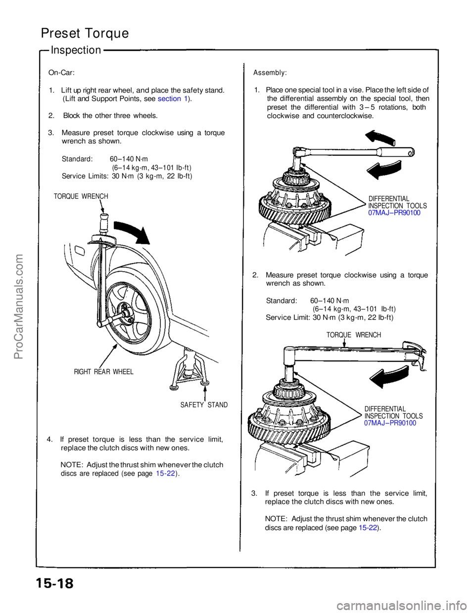
Preset Torque
Inspection
On-Car:
1. Lift up right rear wheel,
and place the safety stand.
(Lift and Support Points, see section 1).
2. Block the other three wheels.
3. Measure preset torque clockwise using a torque wrench as shown.
Standard:
60–140 N·m
(6–14 kg-m, 43–101 Ib-ft)
Service Limits: 30 N·m (3 kg-m, 22 Ib-ft)
TORQUE WRENCH
RIGHT REAR WHEEL SAFETY STAND
4. If preset torque is less than the service limit, replace the clutch discs with new ones.
NOTE: Adjust the thrust shim whenever the clutch
discs are replaced (see page 15-22).
Assembly:
1. Place one special tool in a vise. Place the left side of the differential assembly on the special tool, then
preset the differential with 3 – 5 rotations, both
clockwise and counterclockwise.
DIFFERENTIAL
INSPECTION TOOLS
07MAJ– PR90100
2. Measure preset torque clockwise using a torque wrench as shown.
Standard: 60–140 N·m
(6–14 kg-m, 43–101 Ib-ft)
Service Limit: 30 N·m (3 kg-m, 22 Ib-ft)
TORQUE WRENCH
DIFFERENTIAL
INSPECTION TOOLS
07MAJ – PR90100
3. If preset torque is less than the service limit, replace the clutch discs with new ones.
NOTE: Adjust the thrust shim whenever the clutch
discs are replaced (see page 15-22).
ProCarManuals.com
Page 420 of 1640

Troubleshooting Precautions
EPS Indicator Light
Under normal conditions, the EPS indicator light in the gauge assembly comes on when the ignition switch is turned to
the ON (II) position, then goes off after the engine is started. This indicates that the bulb and its circuits are operating cor-
rectly. If there is any trouble in the system, the EPS indicator light turns on during driving, and the power steering assist is
turned off. When the EPS indicator light comes on, the control unit memorizes the DTC. In this case, the control unit does
not activate the EPS system after the engine starts again but it keeps the EPS indicator light on.
Diagnostic Trouble Code (DTC)
• The lowest DTC is indicated first.
• The DTCs continue blinking until the ignition switch is turned off.
• The DTCs are erased from the control unit when the EPS control unit VBU power supply or connector is disconnected.
• The EPS system can be reset and the control unit's memory can be erased by disconnecting the CLOCK (7.5 A) fuse for
more than ten seconds.
Self-diagnosis:
The CPU (central processing unit) controls the following when it detects a problem during self-diagnosis:
1. Turns the EPS indicator light ON to alert the driver.
2. Power assist stops, and normal manual steering operation resumes (except DTC 21 and DTC 33).
3. The EPS control unit memorizes the diagnostic trouble code (DTC).
4. After the DTC is stored in the control unit, the CPU stops self-diagnosis.
Troubleshooting:
• Before starting the troubleshooting, clear the DTC by disconnecting the CLOCK (7.5 A) fuse for ten seconds or more,
and test-drive the car. Check that the symptom of the trouble appears again, and then troubleshoot. If the problem is an
intermittent problem, the system does not become active after the engine starts even though the problem is solved.
• When both EPS indicator light and A/T "D" indicator light come on, perform the A/T troubleshooting first.
• When the customer's reported problem cannot be verified in the car, ask the customer about the conditions when the
EPS indicator light came ON, then test-drive the car under those conditions, if possible. If the EPS indicator light does
not come ON during the test, check for loose connections or poor contacts at the connectors by wiggling the harness,
etc.
• The connector terminal numbers are viewed from the wire side for the female terminals and from the terminal side for
the male terminals.
• After the repair, test-drive the car and check that the EPS indicator light does not come ON again during the test. (Refer
to the Symptom-to-System Chart for diagnostic period.)ProCarManuals.com
Page 1079 of 1640
II. ENGINE CONTROL MODULE (ECM) Reset Procedure
1. Turn the ignition switch off.
2. Remove the CLOCK (7.5 A) fuse from the under-hood fuse/relay box for 10 seconds to reset ECM.
NOTE: Disconnecting the CLOCK fuse also cancels the radio preset stations and the clock setting. Make note of
the radio presets before removing the fuse so you can reset them.
III. Final Procedure (this procedure must be done after any troubleshooting)
1. Remove the Jumper Wire.
NOTE: If the Service Check Connector is jumped, the MIL will stay on.
2. Do the ECM Reset Procedure.
3. Set the radio preset stations and the clock setting.
(cont'd)
CLOCK
(7.5 A) FUSE
UNDER-HOOD
FUSE/RELAY BOXProCarManuals.com
Page 1107 of 1640
6. Turn the ignition switch OFF.
7. Reconnect the 2P connector on the IAC valve, then
remove CLOCK fuse in the under-hood fuse/relay
box for 10 seconds to reset ECM.
8. Restart and idle the engine with no-load conditions
in which the headlights, blower fan, rear defogger,
cooling fan, and air conditioner are not operating
for one minute, then check the idle speed.
Idle speed should be:
M/T
A/T
800
50 rpm
750
50 rpm
(in or range)ProCarManuals.com
Page 1208 of 1640

Troubleshooting Procedures
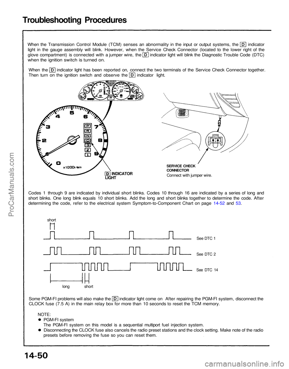
When the Transmission Control Module (TCM) senses an abnormality in the input or output systems, the indicator
light in the gauge assembly will blink. However, when the Service Check Connector (located to the lower right of the glove compartment) is connected with a jumper wire, the indicator light will blink the Diagnostic Trouble Code (DTC)
when the ignition switch is turned on.
When the indicator light has been reported on, connect the two terminals of the Service Check Connector together.
Then turn on the ignition switch and observe the indicator light.
Codes 1 through 9 are indicated by individual short blinks. Codes 10 through 16 are indicated by a series of long and
short blinks. One long blink equals 10 short blinks. Add the long and short blinks together to determine the code. After
determining the code, refer to the electrical system Symptom-to-Component Chart on page 14-52 and 53. SERVICE CHECK
CONNECTOR
Connect with jumper wire.
INDICATOR
Some PGM-FI problems will also make the indicator light come on After repairing the PGM-FI system, disconnect the
CLOCK fuse (7.5 A) in the main relay box for more than 10 seconds to reset the TCM memory.
long short
See DTC 1
See DTC 2
See DTC 14
LIGHT
short
PGM-FI system
The PGM-FI system on this model is a sequential multiport fuel injection system. Disconnecting the CLOCK fuse also cancels the radio preset stations and the clock setting. Make note of the radio
presets before removing the fuse so you can reset them.
NOTE:ProCarManuals.com
Page 1209 of 1640

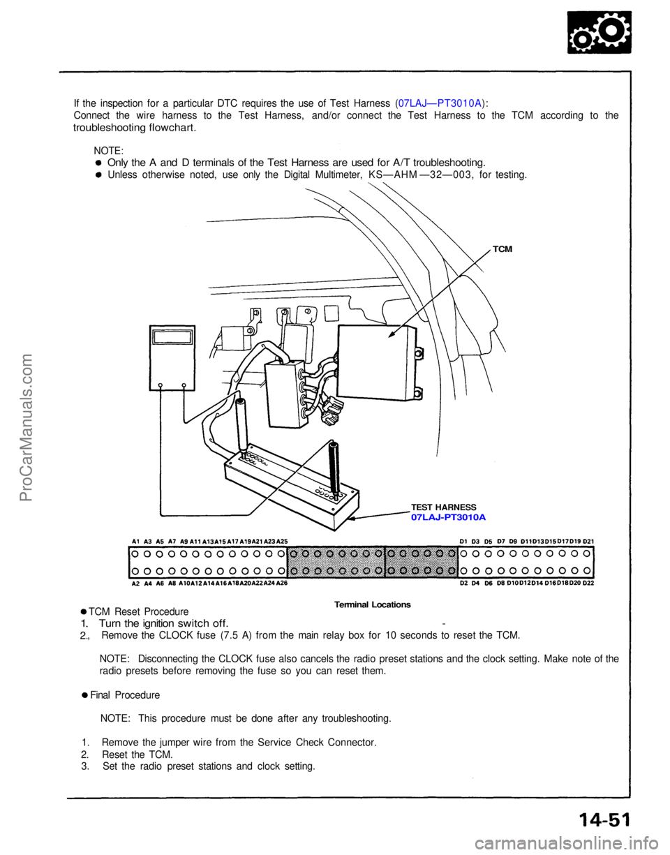
If the inspection for a particular DTC requires the use of Test Harness (07LAJ—PT3010A):
Connect the wire harness to the Test Harness, and/or connect the Test Harness to the TCM according to the
troubleshooting flowchart.
TCM
TEST HARNESS
Terminal Locations
TCM Reset Procedure
Turn the ignition switch off. -
, Remove the CLOCK fuse (7.5 A) from the main relay box for 10 seconds to reset the TCM.
1
2
NOTE: Disconnecting the CLOCK fuse also cancels the radio preset stations and the clock setting. Make note of the
radio presets before removing the fuse so you can reset them.
Final Procedure NOTE: This procedure must be done after any troubleshooting.
1. Remove the jumper wire from the Service Check Connector.
2. Reset the TCM. 3. Set the radio preset stations and clock setting.
Only the A and D terminals of the Test Harness are used for A/T troubleshooting.
Unless otherwise noted, use only the Digital Multimeter, KS—AHM —32—003, for testing.
07LAJ-PT3010A
NOTE:ProCarManuals.com