1991 ACURA NSX ECO mode
[x] Cancel search: ECO modePage 30 of 1640
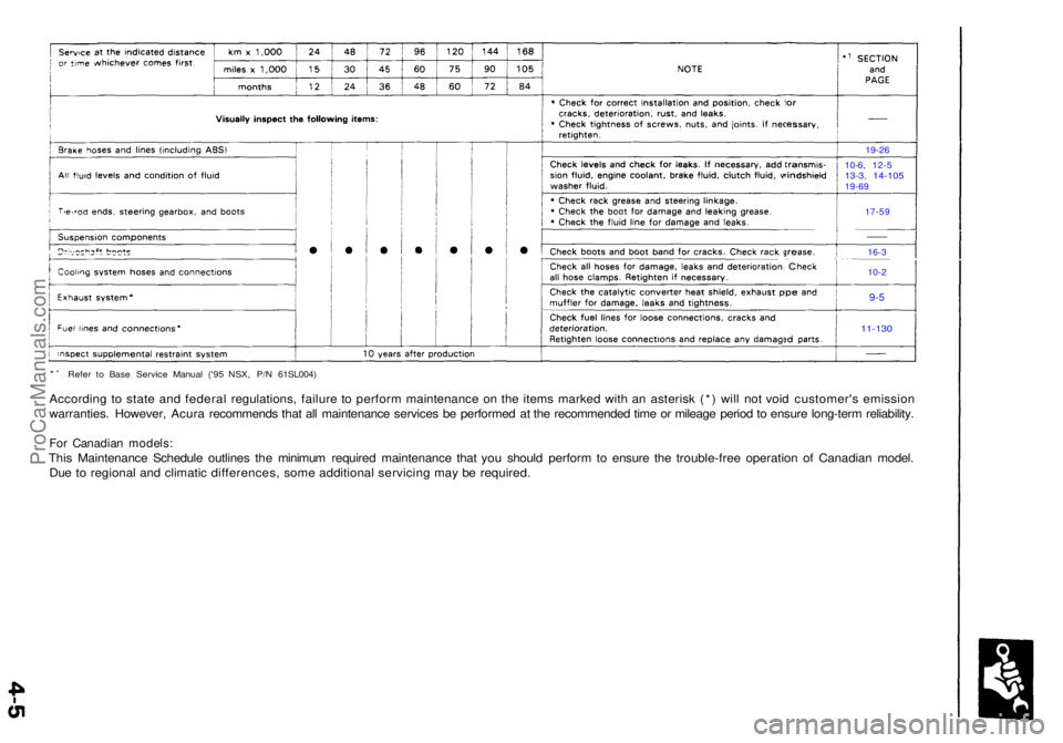
Refer t o Bas e Servic e Manua l ('9 5 NSX , P/ N 61SL004 )
According t o stat e an d federa l regulations , failur e t o perfor m maintenanc e o n th e item s marke d wit h a n asteris k (* ) wil l no t voi d customer' s emissio n
warranties . However , Acur a recommend s tha t al l maintenanc e service s b e performe d a t th e recommende d tim e o r mileag e perio d to ensur e long-ter m reliability .
For Canadia n models :
This Maintenanc e Schedul e outline s th e minimu m require d maintenanc e tha t yo u shoul d perfor m to ensur e th e trouble-fre e operatio n o f Canadia n model .
Du e t o regiona l an d climati c differences , som e additiona l servicin g ma y b e required .
19-26
10-6 , 12- 5
13-3, 14-10 519-69
17-5 9
16-3
10-2
9-5
11-13 0
ProCarManuals.com
Page 66 of 1640
SECTION
and
PAGE
19-26
10-6, 12-5
13-3, 14-105
('91-'93), or('94-'96),19-69('91-'92) or ('93-'96)
17-59
16-3
10-2
9-5
11-130 ('91-'92),('93), or ('94-'96)
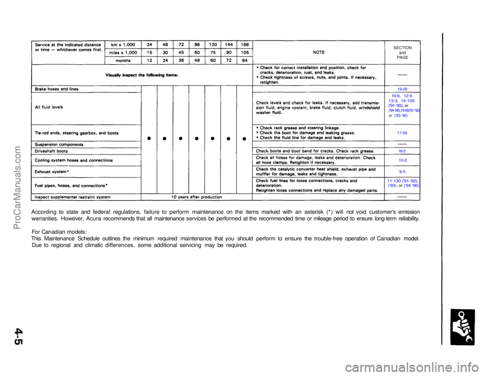
According to state and federal regulations, failure to perform maintenance on the items marked with an asterisk (*) will not void customer's emission
warranties. However, Acura recommends that all maintenance services be performed at the recommended time or mileage period to ensure long-term reliability.
For Canadian models:
This Maintenance Schedule outlines the minimum required maintenance that you should perform to ensure the trouble-free operation of Canadian model. Due to regional and climatic differences, some additional servicing may be required.ProCarManuals.com
Page 80 of 1640
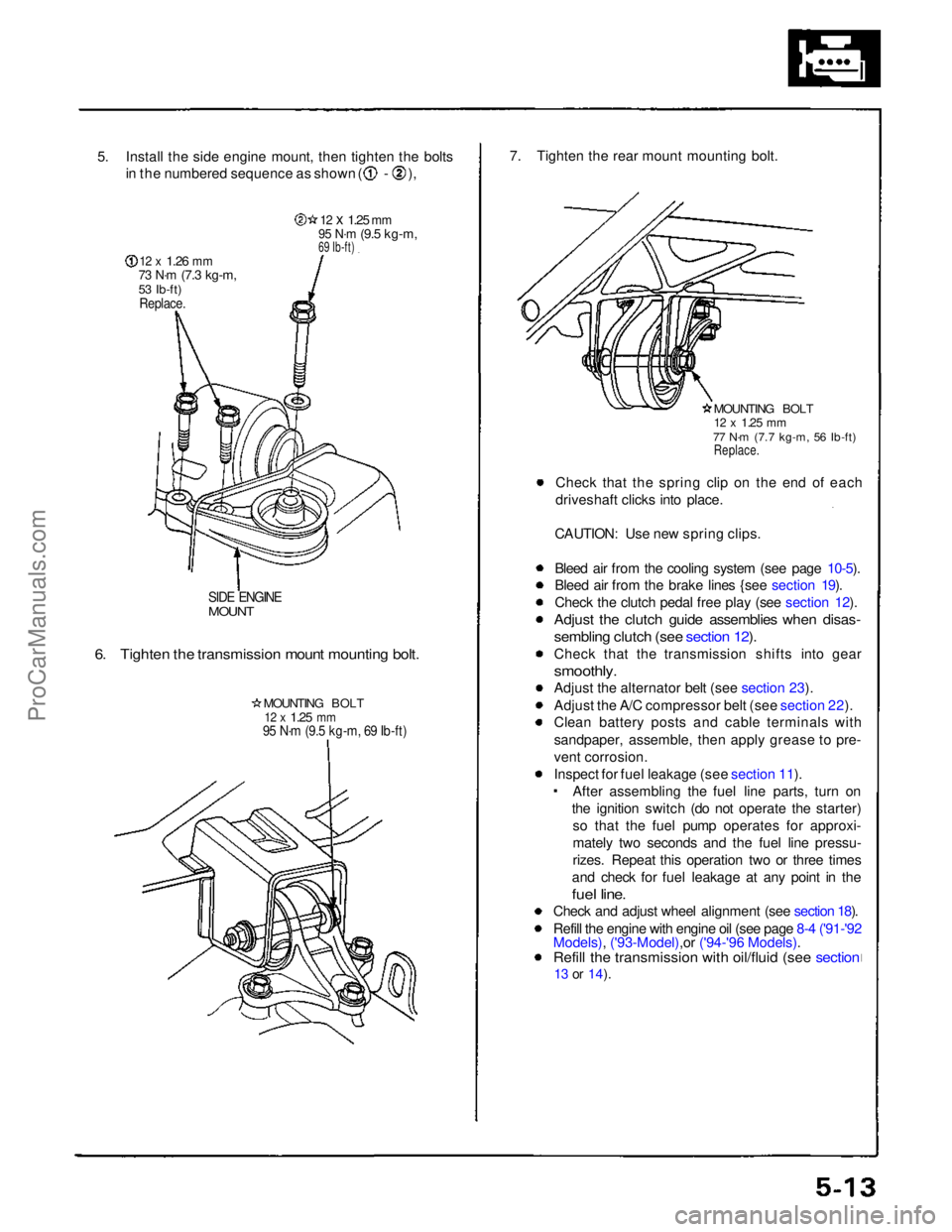
5. Install the side engine mount, then tighten the bolts
in the numbered sequence as shown ( - ),
12 x
1.26
mm
73 N·m
(7.3 kg-m,
53 Ib-ft)
Replace.
12 x
1.25
mm
95 N·m
(9.5 kg-m,
69 Ib-ft)
SIDE ENGINE
MOUNT
6. Tighten the transmission mount mounting bolt.
MOUNTING BOLT
12 x
1.25
mm
95 N·m (9.5 kg-m, 69 Ib-ft)
7. Tighten the rear mount mounting bolt.
MOUNTING BOLT
12 x
1.25
mm
77 N·m (7.7 kg-m, 56 Ib-ft)
Replace.
Check that the spring clip on the end of each
driveshaft clicks into place.
CAUTION: Use new spring clips.
Bleed air from the cooling system (see page 10-5).
Bleed air from the brake lines {see section 19).
Check the clutch pedal free play (see section 12).
Adjust the clutch guide assemblies when disas-
sembling clutch (see section 12).
Check that the transmission shifts into gear
smoothly.
Adjust the alternator belt (see section 23).
Adjust the A/C compressor belt (see section 22).
Clean battery posts and cable terminals with
sandpaper, assemble, then apply grease to pre-
vent corrosion.
Inspect for fuel leakage (see section 11). After assembling the fuel line parts, turn on
the ignition switch (do not operate the starter) so that the fuel pump operates for approxi-
mately two seconds and the fuel line pressu-
rizes. Repeat this operation two or three times
and check for fuel leakage at any point in the
fuel line.
Check and adjust wheel alignment (see section 18).
Refill the engine with engine oil (see page 8-4 ('91-'92
Models), ('93-Model),or ('94-'96 Models).
Refill the transmission with oil/fluid (see section
13 or
14).ProCarManuals.com
Page 228 of 1640

PGM-FI System
System Description
PGM-FI System
The PGM-FI system on this model is a sequential multiport fuel injection system.
Fuel Injector Timing and Duration
The ECM contains memories for the basic discharge durations at various engine speeds and manifold pressures. The
basic discharge duration, after being read out from the memory, is further modified by signals sent from various sensors
to obtain the final discharge duration.
Throttle Valve Control
The ECM controls the throttle valve control motor based on accelerator pedal position, TCS control unit and various sig-
nals. The ECM also controls the idle control function, cruise control function, and other functions with the throttle valve
control.
Ignition Timing Control
• The ECM contains memories for basic ignition timing at various engine speeds and manifold pressures. Ignition timing
is also adjusted for engine coolant temperature.
• A knock control system is also used. When detonation is detected by the knock sensor (KS), the ignition timing is
retarded.
Other Control Functions
1. Starting Control
When the engine is started, the ECM provides a rich mixture by increasing fuel injector duration.
2. Fuel Pump Control
• When the ignition switch is initially turned on, the ECM supplies ground to the PGM-FI main relay that supplies
current to the fuel pump for two seconds to pressurize the fuel system.
• When the engine is running, the ECM supplies ground to the PGM-FI main relay that supplies current to the fuel pump.
• When the engine is not running and the ignition is on, the ECM cuts ground to the PGM-FI main relay which cuts
current to the fuel pump.
• Excellent engine performance is achieved through the use of VTEC (Variable Valve Timing and Valve Lift Electronic
Control System), intake air bypass control and discharge volume control of the fuel pump.ProCarManuals.com
Page 229 of 1640

PGM-FI Syste m
System Descriptio n
3. Fue l Cut-of f Contro l
• Durin g deceleratio n wit h th e throttl e valv e closed , curren t t o th e fue l injector s i s cu t of f t o improv e fue l econom y a t
speed s ove r 1,50 0 rpm .
• Fue l cut-of f actio n als o take s plac e whe n engin e spee d exceeds , 8,30 0 rpm , regardles s o f th e positio n o f th e throttl e
valve , t o protec t th e engin e fro m over-revving .
4 . A/ C Compresso r Clutc h Rela y
Whe n th e EC M receive s a deman d fo r coolin g fro m th e ai r conditionin g system , i t delay s th e compresso r fro m bein g
energized , an d enriche s th e mixtur e to assur e smoot h translatio n to th e A/ C mode .
5 . Evaporativ e Emissio n (EVAP ) Purg e Contro l Solenoi d Valv e
Whe n th e engin e coolan t temperatur e is belo w 153° F (67°C) , th e EC M control s th e EVA P purg e contro l solenoi d valv e
whic h cut s vacuu m to th e EVA P purg e contro l caniste r diaphragm .
6 . Intak e Ai r Bypas s (IAB ) Contro l Solenoi d Valv e
Whe n th e engin e spee d is belo w 4,80 0 rpm , th e IA B contro l solenoi d valv e is activate d b y a signa l fro m th e ECM . Intak e
ai r the n flow s throug h th e smalle r chamber , an d hig h torqu e is delivered . T o increas e ai r flo w a t engin e speed s highe r
tha n 4,80 0 rpm , th e solenoi d valv e is deactivate d b y th e ECM , an d th e intak e ai r flow s throug h th e large r chamber .
7 . Exhaus t Ga s Recirculatio n (EGR ) Contro l Solenoi d Valv e
Whe n th e EG R is require d fo r contro l o f oxide s o f nitroge n (NOx ) emissions , th e EC M supplie s groun d t o th e EG R
contro l solenoi d valv e whic h supplie s regulate d vacuu m to th e EG R valve .
EC M Fail-safe/Back-u p Function s
1 . Fail-Saf e Functio n
Whe n a n abnormalit y occur s i n a signa l fro m a sensor , th e EC M ignore s tha t signa l an d assume s a pre-programme d
valv e fo r tha t senso r tha t allow s th e engin e t o continu e t o run .
2 . Back-u p Functio n
Whe n a n abnormalit y occur s i n th e EC M itself , th e fue l injector s ar e controlle d b y a back-u p circui t independen t o f th e
syste m in orde r t o permi t minima l driving .
3 . Self-diagnosi s Functio n [Malfunctio n Indicato r Lam p (MIL) ]
Whe n a n abnormalit y occur s i n a signa l fro m a sensor , th e EC M light s th e MI L an d store s th e diagnosti c troubl e cod e
i n erasabl e memory . Whe n th e ignitio n i s initiall y turne d on , th e EC M supplie s groun d fo r th e MI L fo r tw o second s t o
chec k th e MI L bul b condition .
ProCarManuals.com
Page 521 of 1640
Anti-lock Brake System (ABS) Description
Features/Construction/Operation (cont'd)
ABS Control Unit
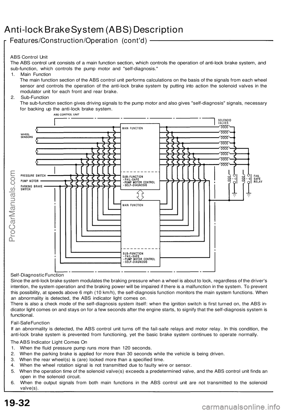
The ABS control unit consists of a main function section, which controls the operation of anti-lock brake system, and
sub-function, which controls the pump motor and "self-diagnosis."
1. Main Function
The main function section of the ABS control unit performs calculations on the basis of the signals from each wheel
sensor and controls the operation of the anti-lock brake system by putting into action the solenoid valves in the
modulator unit for each front and rear brake.
2. Sub-Function
The sub-function section gives driving signals to the pump motor and also gives "self-diagnosis" signals, necessary
for backing up the anti-lock brake system.
Self-Diagnostic Function
Since the anti-lock brake system modulates the braking pressure when a wheel is about to lock, regardless of the driver's
intention, the system operation and the braking power will be impaired if there is a malfunction in the system. To prevent
this possibility, at speeds above 6 mph (10 km/h), the self-diagnosis function monitors the main system functions. When
an abnormality is detected, the ABS indicator light comes on.
There is also a check mode of the self-diagnosis system itself: when the ignition switch is first turned on, the ABS in-
dicator light comes on and stays on for a few seconds after the engine starts, to signify that the self-diagnosis system is
functional.
Fail-Safe Function
If an abnormality is detected, the ABS control unit turns off the fail-safe relays and motor relay. In this condition, the
anti-lock brake system is prevented from functioning, yet the basic brake system continues to operate normally.
The ABS Indicator Light Comes On
1. When the fluid pressure pump runs more than 120 seconds.
2. When the parking brake is applied for more than 30 seconds while the vehicle is being driven.
3. When the rear wheel(s) is (are) locked more than a specified time.
4. When the wheel rotation signal is not transmitted due to faulty wire or sensor.
5. When the operation time of the solenoid valve(s) exceeds a predetermined valve, and the ABS control unit finds an
open in the solenoid circuit.
6. When the output signals from both main functions in the ABS control unit are not transmitted to the solenoid
valve(s).ProCarManuals.com
Page 527 of 1640
ALB Checke r
Function Tes t
NOTE :
• Th e AL B checke r i s designe d t o confir m prope r
operatio n of the anti-loc k brak e syste m (ABS ) b y
simulatin g eac h syste m functio n an d operatin g con -
dition . Befor e usin g th e checker , confir m tha t th e
anti-loc k brak e syste m (ABS ) indicato r ligh t i s no t in -
dicatin g som e othe r proble m wit h th e system . Th e
light shoul d g o o n whe n th e ignitio n i s firs t turne d o n
an d the n g o of f an d sta y of f on e secon d afte r th e
engin e i s started .
• Th e checke r shoul d b e use d throug h modes ,
1-5, t o
confir m prope r operatio n of the system , i n an y on e
of th e followin g situations :
Afte r replacin g an y AB S component .
Afte r replacin g o r bleedin g th e syste m flui d ( 0
mod e no t necessary) .
Afte r an y bod y o r suspensio n repai r tha t ma y
hav e affecte d th e sensor s o r thei r wiring .
• Th e procedur e fo r mode s
1-5 ar e o n thi s pag e an d
19-42 , mod e 0 (whee l senso r signal ) i s o n pag e
19-43 .
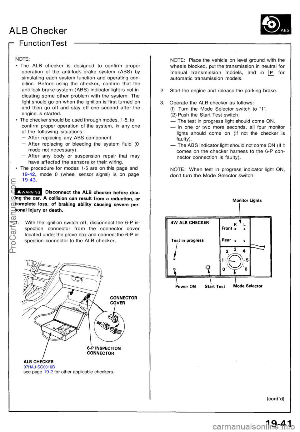
1. Wit h th e ignitio n switc h off , disconnec t th e 6- P in -
spectio n connecto r fro m th e connecto r cove r
locate d unde r th e glov e bo x an d connec t th e 6- P in -
spectio n connecto r t o th e AL B checker .
07HAJ-SG0010Bsee pag e 19- 2 fo r othe r applicabl e checkers .
NOTE: Plac e th e vehicl e o n leve l ground with th e
wheel s blocked , pu t th e transmissio n i n neutra l fo r
manua l transmissio n models , an d i n fo r
automati c transmissio n models .
2 . Star t th e engin e an d releas e th e parkin g brake .
3 . Operat e th e AL B checke r a s follows :
(1 ) Tur n th e Mod e Selecto r switc h t o "1" .
(2 ) Pus h th e Star t Tes t switch :
— Th e tes t i n progres s ligh t shoul d com e ON .
— In on e o r tw o mor e seconds , al l fou r monito r
light s shoul d com e o n (I f no t th e checke r i s
faulty) .
— Th e AB S indicato r ligh t shoul d no t com e O N (I f i t
come s o n th e checke r harnes s t o th e 6- P con -
necto r connectio n i s faulty) .
NOTE : Whe n tes t i n progres s indicato r ligh t ON ,
don't tur n th e Mod e Selecto r switch .
ProCarManuals.com
Page 528 of 1640
ALB Checker
Function Test (cont'd)
4. Turn the Mode Selector switch further to "2". 5. Depress the brake pedal firmly and push the Start
Test switch
The ABS indicator light should not go on while the
Test in Progress light is ON. There should bekickback on the brake pedal. If not as described, go
to troubleshooting, page 19-44 ('91-'92) ('93-'96).
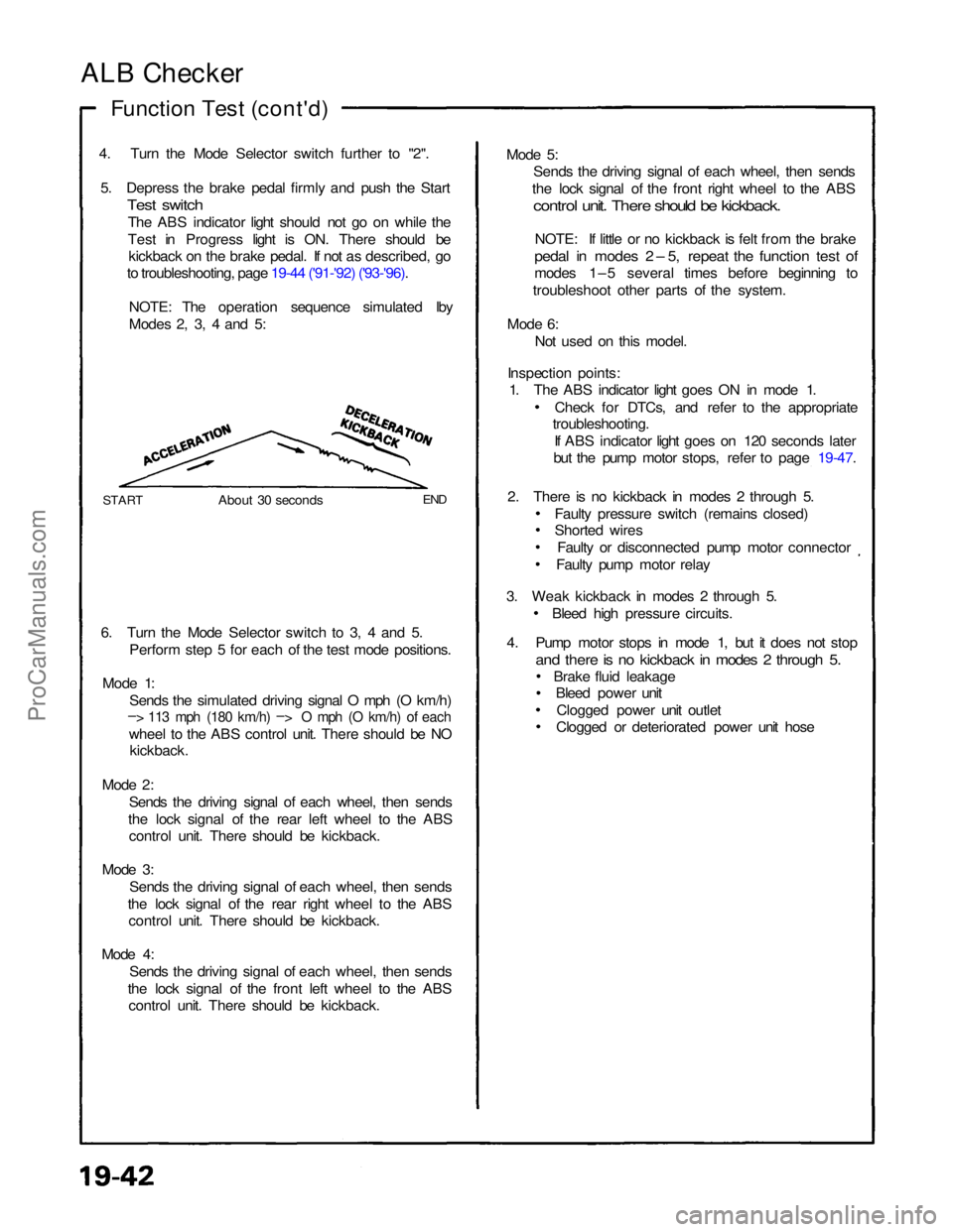
NOTE: The operation sequence simulated lby
Modes 2, 3, 4 and 5:
START
About 30 seconds
END
6. Turn the Mode Selector switch to 3, 4 and 5. Perform step 5 for each of the test mode positions.
Mode 1: Sends the simulated driving signal O mph (O km/h)
– > 113 mph (180 km/h) –
>
O mph (O km/h) of each
wheel to the ABS control unit. There should be NO
kickback.
Mode 2: Sends the driving signal of each wheel, then sends
the lock signal of the rear left wheel to the ABS control unit. There should be kickback.
Mode 3: Sends the driving signal of each wheel, then sends
the lock signal of the rear right wheel to the ABS control unit. There should be kickback.
Mode 4: Sends the driving signal of each wheel, then sends
the lock signal of the front left wheel to the ABS control unit. There should be kickback. Mode 5:
Sends the driving signal of each wheel, then sends
the lock signal of the front right wheel to the ABS
control unit. There should be kickback.
NOTE: If little or no kickback is felt from the brake
pedal in modes 2 – 5, repeat the function test of
modes 1–5 several times before beginning to
troubleshoot other parts of the system.
Mode 6: Not used on this model.
Inspection points: 1. The ABS indicator light goes ON in mode 1.
Check for DTCs, and refer to the appropriate
troubleshooting.
If ABS indicator light goes on 120 seconds later
but the pump motor stops, refer to page 19-47.
2. There is no kickback in modes 2 through 5. Faulty pressure switch (remains closed)
Shorted wiresFaulty or disconnected pump motor connector
Faulty pump motor relay
3. Weak kickback in modes 2 through 5. Bleed high pressure circuits.
4. Pump motor stops in mode 1, but it does not stop
and there is no kickback in modes 2 through 5.
Brake fluid leakageBleed power unit
Clogged power unit outlet
Clogged or deteriorated power unit hoseProCarManuals.com