Page 5 of 1640
Warning/Caution Labe l Location s
SRS CAUTIO N LABELS : Refe r t o pag e 1- 6
FROZE NBATTER Y CAUTIO N
AI R CONDITIONIN G
R-134 a CAUTIO N
(U.S.A. only )
ENGIN E COOLAN TCAUTION • PRECAUTIO N
ABS CAUTIO N
ABS an d BRAK EFLUID CAUTIO N
RETRACTABL EHEADLIGHT CAUTIO N
EMISSION CONTRO L
INFORMATIO N an d
VACUU M HOS E
ROUTIN G DIAGRA M
BATTERYCAUTION
RADIATO R BLEE DPLUG CAUTIO N
EXPANSIO NTANK CA PCAUTIO N
SPAR K PLU G
CAUTIO N
TIRE INFORMATIO N
ProCarManuals.com
Page 827 of 1640
Switches
The lighting system is controlled by five switches and the turn signal cancel unit.
HEADLIGHT SWITCH TURN SIGNAL CANCEL UNIT
HAZARD WARNING SWITCH
TURN SIGNAL and DIMMER SWITCH
TURN SIGNAL CANCEL SWITCHProCarManuals.com
Page 862 of 1640
Side Marker/Turn Signal/Hazard Flasher System
Component Location Index
SRS components are located in this area. Review the SRS component locations, precautions, and procedures in the SRS
section (24) before performing repairs or service.
TURN SIGNAL INDICATOR LIGHTS(In the gauge assembly)
Gauge Assembly, page 23-125 HAZARD WARNING SWITCH
Removal, page 23-220
Test, page 23-221
HEADLIGHT SWITCH
Test, page 23-181
Replacement, page 23-182
TURN SIGNAL/HAZARD RELAY
Input Test, page 23-218
UNDER-DASH FUSE BOX TURN SIGNAL SWITCH
Test, page 23-181
Replacement, page 23-182 TURN SIGNAL CANCEL UNIT
Input Test, page 23-219
SIDE MARKER FLASHER CIRCUIT
(In the integrated control unit)
Input Test, page 23-168 ('94-'96) ('91-'93)ProCarManuals.com
Page 960 of 1640
Warning/Caution Label Locations
SRS CAUTION LABELS: Refer to page 1-8.
FROZEN
BATTERY CAUTION
BATTERY
CAUTION
RADIATOR BLEED
PLUG CAUTION
AIR CONDITIONING
R-134a CAUTION (U.S.A only)
EXPANSION
TANK CAP
CAUTION
ENGINE COOLANT CAUTION PRECAUTION
SPARK PLUG
CAUTION
TIRE INFORMATION
ABS CAUTION
ABS and BRAKE
FLUID CAUTION
RETRACTABLE
HEADLIGHT CAUTION
EMISSION CONTROL
INFORMATION and
VACUUM HOSE
ROUTING DIAGRAM
(cont'd)ProCarManuals.com
Page 969 of 1640
Warning/Caution Label Locations
SRS CAUTION LABELS: Refer to page 1-8.
FROZEN
BATTERY CAUTION
BATTERY
CAUTION
RADIATOR BLEED
PLUG CAUTION
AIR CONDITIONING R-134a CAUTION(U.S.A only)
EXPANSION
TANK CAP CAUTION
ENGINE COOLANT
CAUTION • PRECAUTION
SPARK PLUG
CAUTION
TIRE INFORMATION
EMISSION CONTROL
INFORMATION and
VACUUM HOSE
ROUTING DIAGRAM
RETRACTABLE
HEADLIGHT CAUTION
ABS and BRAKE
FLUID CAUTION ABS CAUTION
(cont'd)ProCarManuals.com
Page 1310 of 1640
12. Install the knee bolster and pad.
13. Connect the foot well light harness and light-on
warning chime to the dashboard lower panel, then
install the dashboard lower panel.
KNEE
BOLSTER
KNEE BOLSTER
PAD
DASHBOARD
LOWER PANEL
14. Install the steering wheel and airbag assembly to the column (see page 17-10).ProCarManuals.com
Page 1418 of 1640

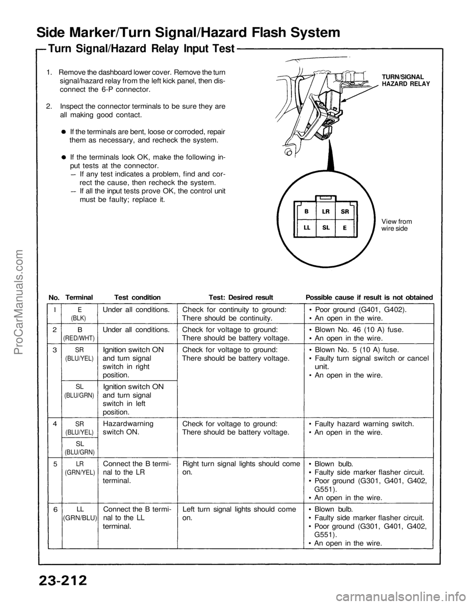
Side Marker/Turn Signal/Hazard Flash System
Turn Signal/Hazard Relay Input Test
1. Remove the dashboard lower cover. Remove the turn signal/hazard relay from the left kick panel, then dis-
connect the 6-P connector.
2. Inspect the connector terminals to be sure they are all making good contact.
If the terminals are bent, loose or corroded, repair
them as necessary, and recheck the system.
If the terminals look OK, make the following in-
put tests at the connector. If any test indicates a problem, find and cor-
rect the cause, then recheck the system. If all the input tests prove OK, the control unit
must be faulty; replace it.
View from
wire side
TURN/SIGNAL
HAZARD RELAY
1
2
3
4
5
6
B
(RED/WHT)
SR
(BLU/YEL)
SL
(BLU/GRN)
SR
(BLU/YEL)
SL
(BLU/GRN)
LR
(GRN/YEL)
LL
(GRN/BLU)
Test condition
Under all conditions.
Ignition switch ON
and turn signal
switch in right position.
Ignition switch ON
and turn signal switch in left
position.
Connect the B termi-
nal to the LR
terminal.
Connect the B termi-
nal to the LL
terminal.
Test: Desired result
Check for continuity to ground:
There should be continuity.
Check for voltage to ground:
There should be battery voltage.
Check for voltage to ground:
There should be battery voltage.
Check for voltage to ground:
There should be battery voltage.
Right turn signal lights should come
on.
Left turn signal lights should come
on.
Possible cause if result is not obtained
Poor ground (G401, G402).
An open in the wire.
Blown No. 46 (10 A) fuse.
An open in the wire.
Blown No. 5 (10 A) fuse.
Faulty turn signal switch or cancel
unit.
An open in the wire.
Faulty hazard warning switch.
An open in the wire.
Blown bulb.
Faulty side marker flasher circuit.
Poor ground (G301, G401, G402,
G551).
An open in the wire.
Blown bulb.
Faulty side marker flasher circuit.
Poor ground (G301, G401, G402,
G551).
An open in the wire.
E
(BLK)
Terminal
No.
Under all conditions.
Hazard warning
switch ON.ProCarManuals.com
Page 1421 of 1640
Hazard Warning Switch Light Bulb
Replacement
1. Remove the steering column covers.
2. Remove the screws from the hazard warning and wiper switches.
HAZARD
WARNING SWITCH
3. Remove the two screws from the back of switch. HAZARD WARNING
SWITCH
4. Slide the hazard warning switch out of the housing
as shown.
5. Remove the bulb from the hazard warning switch by
turning it 45°.
HAZARD WARNING SWITCH
HOUSING BULB (0.91W) Hazard Warning Switch Test
1. Remove the dashboard lower cover (see page
23-126).
2. Disconnect the 18-P connector from the floor wire harness.
3. Check for continuity between the terminals in each
switch position according to the table.
HAZARD WARNING SWITCH
18-P CONNECTOR
View from wire side M: Not usedProCarManuals.com