Page 20 of 1640
Differential (Manua l Transmission ) — Sectio n 1 5
Differentia l (Automati c Transmission ) — Sectio n 1 5
ProCarManuals.com
Page 56 of 1640
Differential (Manua l Transmission ) — Sectio n 1 5
Differentia l (Automati c Transmission ) — Sectio n 1 5
ProCarManuals.com
Page 305 of 1640

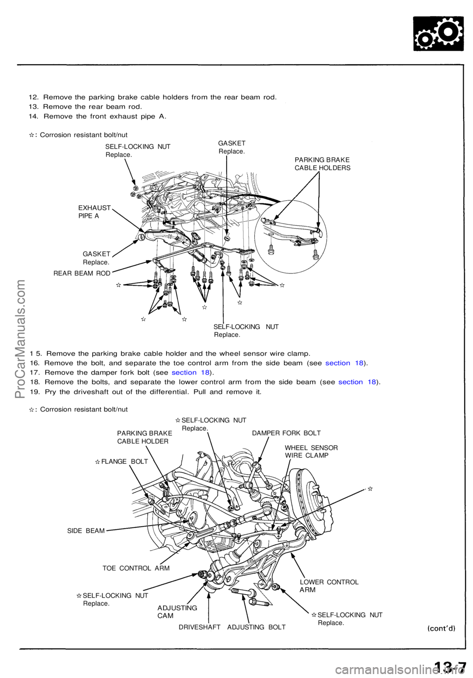
12. Remov e th e parkin g brak e cabl e holder s fro m th e rea r bea m rod .
13 . Remov e th e rea r bea m rod .
14 . Remov e th e fron t exhaus t pip e A .
Corrosio n resistan t bolt/nu t
SELF-LOCKIN G NU T
Replace .
EXHAUS TPIPE A
GASKE T
Replace .
REAR BEA M RO D
GASKE TReplace .PARKING BRAK E
CABL E HOLDER S
SELF-LOCKIN G NU T
Replace .
1 5 . Remov e th e parkin g brak e cabl e holde r an d th e whee l senso r wir e clamp .
16 . Remov e th e bolt , an d separat e th e to e contro l ar m fro m th e sid e bea m (se e sectio n 18 ).
17 . Remov e th e dampe r for k bol t (se e sectio n 18 ).
18 . Remov e th e bolts , an d separat e th e lowe r contro l ar m fro m th e sid e bea m (se e sectio n 18 ).
19 . Pr y th e driveshaf t ou t o f th e differential . Pul l an d remov e it .
Corrosio n resistan t bolt/nu t
PARKIN G BRAK E
CABL E HOLDE RSELF-LOCKIN
G NU T
Replace .
FLANG E BOL T DAMPE
R FOR K BOL T
WHEE L SENSO R
WIR E CLAM P
SID E BEA M
SELF-LOCKIN G NU T
Replace .ADJUSTIN GCAM
DRIVESHAF T ADJUSTIN G BOL T LOWE
R CONTRO L
ARM
SELF-LOCKIN G NU T
Replace .
TO
E CONTRO L AR M
ProCarManuals.com
Page 306 of 1640

Transmission Assembly
Removal
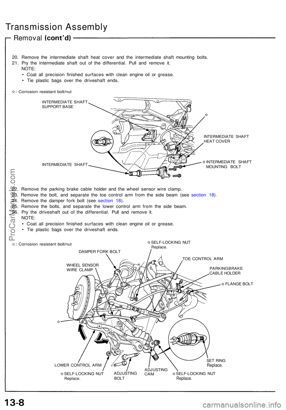
20. Remove the intermediate shaft heat cover and the intermediate shaft mounting bolts.
21. Pry the intermediate shaft out of the differential. Pull and remove it. NOTE:
• Coat all precision finished surfaces with clean engine oil or grease.
• Tie plastic bags over the driveshaft ends.
Corrosion resistant bolt/nut
INTERMEDIATE SHAFT
SUPPORT BASE
INTERMEDIATE SHAFT INTERMEDIATE SHAFT
HEAT COVER
INTERMEDIATE SHAFT
MOUNTING BOLT
22. Remove the parking brake cable holder and the wheel sensor wire clamp.
23. Remove the bolt, and separate the toe control arm from the side beam (see section 18).
24. Remove the damper fork bolt (see section 18).
25. Remove the bolts, and separate the lower control arm from the side beam. 26. Pry the driveshaft out of the differential. Pull and remove it. NOTE:
• Coat all precision finished surfaces with clean engine oil or grease.
• Tie plastic bags over the driveshaft ends.
Corrosion resistant bolt/nut
DAMPER FORK BOLT SELF-LOCKING NUT
Replace.
TOE CONTROL ARM
WHEEL SENSOR WIRE CLAMP PARKING BRAKE
CABLE HOLDER
FLANGE BOLT
LOWER CONTROL ARM SELF-LOCKING NUTReplace. ADJUSTING
BOLT
ADJUSTING
CAM
SELF-LOCKING NUT
Replace.
SET RING
Replace.ProCarManuals.com
Page 310 of 1640

Transmission Housing
Removal
NOTE: Place the clutch housing on two pieces of wood
thick enough to keep the mainshaft from hitting the
workbench.
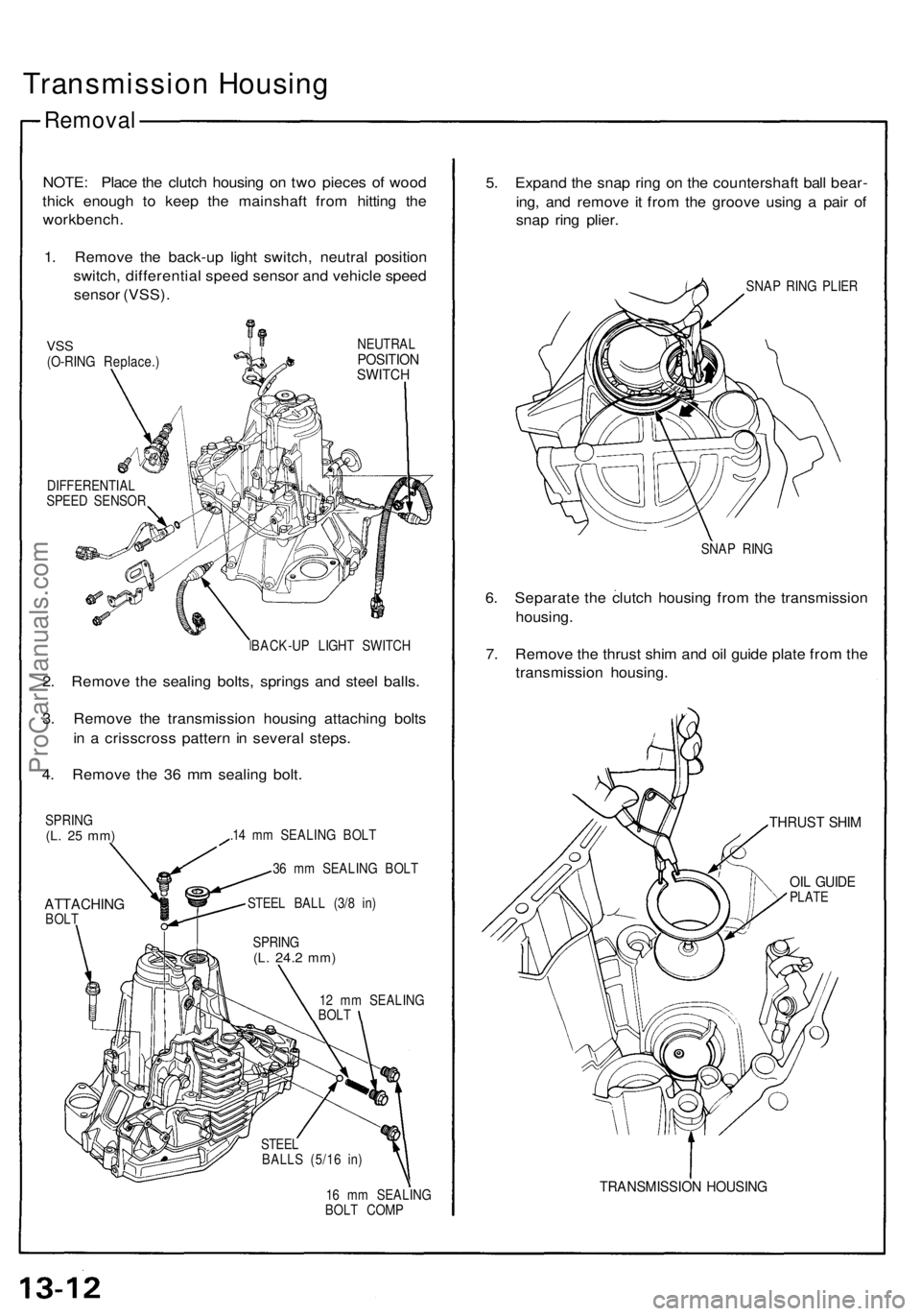
1. Remove the back-up light switch, neutral position
switch, differential speed sensor and vehicle speed
sensor (VSS).
VSS
(O-RING Replace.)
NEUTRAL
POSITION
SWITCH
DIFFERENTIAL
SPEED SENSOR
BACK-UP LIGHT SWITCH
2. Remove the sealing bolts, springs and steel balls.
3. Remove the transmission housing attaching bolts
in a crisscross pattern in several steps.
4. Remove the 36 mm sealing bolt.
SPRING
(L. 25 mm)
ATTACHING
BOLT
.14 mm SEALING BOLT
36 mm SEALING BOLT
STEEL BALL (3/8 in)
12 mm SEALING
BOLT
16 mm SEALING
BOLT COMP
5. Expand the snap ring on the countershaft ball bear-
ing, and remove it from the groove using a pair of
snap ring plier.
SNAP RING PLIER
SNAP RING
6. Separate the clutch housing from the transmission
housing.
7. Remove the thrust shim and oil guide plate from the
transmission housing.
THRUST SHIM
OIL GUIDE
PLATE
TRANSMISSION HOUSING
SPRING
(L.
24.2
mm)
STEEL
BALLS (5/16 in)ProCarManuals.com
Page 316 of 1640
Mainshaft, Countershaft,
Differential Assemblies
Removal
1. Remove the change holder assembly from the
clutch housing.
CLUTCH
HOUSING
CHANGE HOLDER
ASSEMBLY
2. Remove the mainshaft assembly and countershaft
assembly with the shift fork from the clutch
housing.
NOTE: Tape the mainshaft splines to protect them
before removing the mainshaft and countershaft
assemblies.
MAINSHAFT
ASSEMBLY
COUNTERSHAFT
ASSEMBLY
SHIFT FORK
ASSEMBLY
Tape the mainshaft
splines.
SPRING
WASHER
CLUTCH HOUSINGProCarManuals.com
Page 317 of 1640
3. Remove the differential assembly from the clutch
housing.
DIFFERENTIAL ASSEMBLY
CLUTCH
HOUSINGProCarManuals.com
Page 347 of 1640
Transmission
Reassembly
1. Install the oil seal, shift arm, and shift lever in the
transmission housing.
8 x 1.0 mm SPECIAL BOLT
32 N-m (3.2 kg-m, 23 Ib-ft)
SPRING WASHER
SHIFT ARM
TRANSMISSION HOUSING
SHIFT LEVER
OIL SEAL
Replace.
2. Install the shift detent spring and spring set plate.
8 x 1.25 mm SPECIAL BOLT
26 N-m (2.6 kg-m, 19 Ib-ft)
SPRING SET PLATE
SHIFT DETENT SPRING
3. Install the oil seal, select arm, and select lever in
the clutch housing.
8 x 1.0 mm SPECIAL BOLT
32 N-m (3.2 kg-m, 23 Ib-ft)
SPRING WASHER
SELECT ARM
OIL SEAL
Replace.
CLUCH
HOUSING
SELECT LEVER
4. Install the differential assembly into the clutch
housing.
DIFFERENTIAL ASSEMBLY
CLUTCH HOUSINGProCarManuals.com