Page 5 of 1640
Warning/Caution Labe l Location s
SRS CAUTIO N LABELS : Refe r t o pag e 1- 6
FROZE NBATTER Y CAUTIO N
AI R CONDITIONIN G
R-134 a CAUTIO N
(U.S.A. only )
ENGIN E COOLAN TCAUTION • PRECAUTIO N
ABS CAUTIO N
ABS an d BRAK EFLUID CAUTIO N
RETRACTABL EHEADLIGHT CAUTIO N
EMISSION CONTRO L
INFORMATIO N an d
VACUU M HOS E
ROUTIN G DIAGRA M
BATTERYCAUTION
RADIATO R BLEE DPLUG CAUTIO N
EXPANSIO NTANK CA PCAUTIO N
SPAR K PLU G
CAUTIO N
TIRE INFORMATIO N
ProCarManuals.com
Page 85 of 1640
Valve Clearance
Adjustment (cont'd)
3. Manually inspect the rocket arms for independentoperation (see page 6-7, 8 ('94-'96), 6-36, 37 ('91-'93).
4. Adjust valves on No.1 cylinder.
• Adjusting screws are on primary and secondary
rocker arms,
Intake: 0.15-0.19 mm (0.006-0.007 in)
Exhaust: 0.17-0.21 mm (0.007-0.008 in)
5. Loosen the locknut, and turn the adjustment screw
until the feeler gauge slides back and forth with a
slight amount of drag.
INTAKE:
TAPPET ADJUSTER
07MAA–PR70110
FEELER
GAUGE
TAPPET LOCKNUT
WRENCH
07MAA–PR70120
EXHAUST: NOTE: Use a mirror to check if the special tool is
positioned on the locknut correctly.
FEELER
GAUGE
6. Tighten the locknut and check the clearance again.
Repeat adjustment if necessary.
INTAKE:
FEELER
GAUGE
LOCKNUT
7 x
0.75
mm
20 N·m
(2.0
kg-m.
14 Ib-ft)
EXHAUST:
FEELER
GAUGE
LOCKNUT
7
x
0.75
mm
20 N·m
(2.0
kg-m,
14 Ib-ft)ProCarManuals.com
Page 89 of 1640

Timing Belt
Inspection
1. Remove the ignition coil covers and harness clamps.
2. Disconnect the connectors, then remove the ignition
coils.
3. Remove the cylinder head covers,
4. Inspect the timing belt for cracks and coolant or oil soaking.
NOTE:
Replace the belt if coolant or oil soaked.
Remove any oil or solvent that gets on the belt.
Inspect this area
for wear.
Rotate pulley and
Inspect belt.
Tension Adjustment
CAUTION:
Always adjust timing belt tension with the engine cold
Do not rotate the crankshaft when the adjusting bolt
is loose (the timing belt will skid over the teeth of
the rear intake caimshaft pulley).
Adjust the belt tension only when the belt has been
removed and reinstalled or replaced.
NOTE:
Tensioner is spring-loaded to apply proper tension to
the belt automatically after making the following ad-
justment. Inspect the timing belt before adjusting the belt
tension.
Always rotate the crankshaft clockwise. Rotating it
counterclockwise may result in improper adjustment
of the belt tension or cause the belt to jump a tooth
on the camshaft pulleys.
Install the timing beIt with the No. 1 piston at TDC
(see pages 6-18 ('91-'93) or ('94-'96),19 ('91-'93)
or ('94-'96) Remove the slack in the sequence of , and
by turning each camshaft pulley slightly.
Loosen the timing belt adjusting bolt 180° (the slack
at should be eliminated).
Then, tighten the timing belt adjusting bolt.
Verify that No. 1 piston is at TDC (see page 6-19).
Rotate the crankshaft clockwise nine teeth on the
camshaft pulley (The blue mark on the crankshaft pul- ley should line up with the pointer on lower cover).
Loosen
the
timing
belt
adjusting
bolt.
Retighten the adjusting bolt, torque to 43 N·m (4.3
kg-m, 31 Ib-fl).
Direction
of rotation
POINTER ON
LOWER COVER
ADJUSTING BOLT
43N·m (4.3 kg-m,
31 Ib-ft)
BLUE MARK
TDC MARK
ProCarManuals.com
Page 107 of 1640
Rocker Arm s an d Los t Motio n Assemblie s
Inspection
NOTE: Whe n reassemblin g th e primar y rocke r arm , care -
full y appl y ai r pressur e t o th e oi l passag e o f th e rocke r
arm.
PRIMAR Y ROCKE R AR M
MI D ROCKE R AR M
SECONDAR Y
ROCKE R AR M
PISTON S
Inspect th e rocke r ar m pistons . Pus h the m manually .
— If the y d o no t mov e smoothly , replac e th e rocke r
ar m assembly .
PRIMARYMID
SECONDAR Y
Check pisto n movemen t
NOTE:
• Appl y oi l t o th e piston s whe n reassembling .
• Bundl e th e rocke r arm s wit h rubbe r band s t o
kee p the m togethe r a s sets . 2
. Remov e th e los t motio n assembl y fro m th e cylinde r
hea d an d inspec t it . Pushin g i t gentl y wit h th e finge r
wil l caus e i t t o sin k slightly . Increasin g th e forc e o n
i t wil l caus e i t t o sin k deeper .
— If th e los t motio n assembl y doe s no t mov e
smoothly , replac e it .
Pus h
LOS T MOTIO N ASSEMBL Y
ProCarManuals.com
Page 111 of 1640

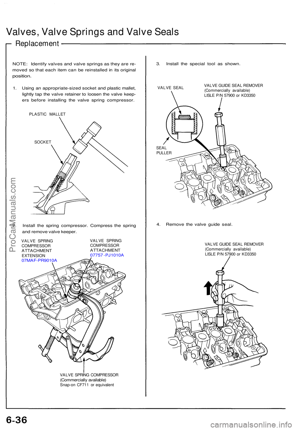
Valves, Valv e Spring s an d Valv e Seal s
Replacemen t
NOTE: Identif y valve s an d valv e spring s a s the y ar e re -
move d s o tha t eac h ite m ca n b e reinstalle d in it s origina l
position .
1. Usin g a n appropriate-size d socke t an d plasti c mallet ,
lightl y ta p th e valv e retaine r t o loose n th e valv e keep -
er s befor e installin g th e valv e sprin g compressor .
PLASTIC MALLE T
SOCKE T
2. Instal l th e sprin g compressor . Compres s th e sprin g
an d remov e valv e keeper .
VALVE SPRIN G
COMPRESSO R
ATTACHMENTEXTENSION07MAF-PR9010 A
VALVE SPRIN G
COMPRESSO R
ATTACHMENT07757 - PJ1010 A
VALVE SPRIN G COMPRESSO R(Commercially available )Snap-on CF71 1 o r equivalen t
3. Instal l th e specia l too l a s shown .
VALVE SEA L VALV
E GUID E SEA L REMOVE R
(Commerciall y available )
LISL E P/ N 5790 0 o r KD335 0
SEALPULLE R
4. Remov e th e valv e guid e seal .
VALV E GUID E SEA L REMOVE R
(Commerciall y available )
LISL E P/ N 5790 0 o r KD335 0
ProCarManuals.com
Page 125 of 1640

Camshafts
Installation
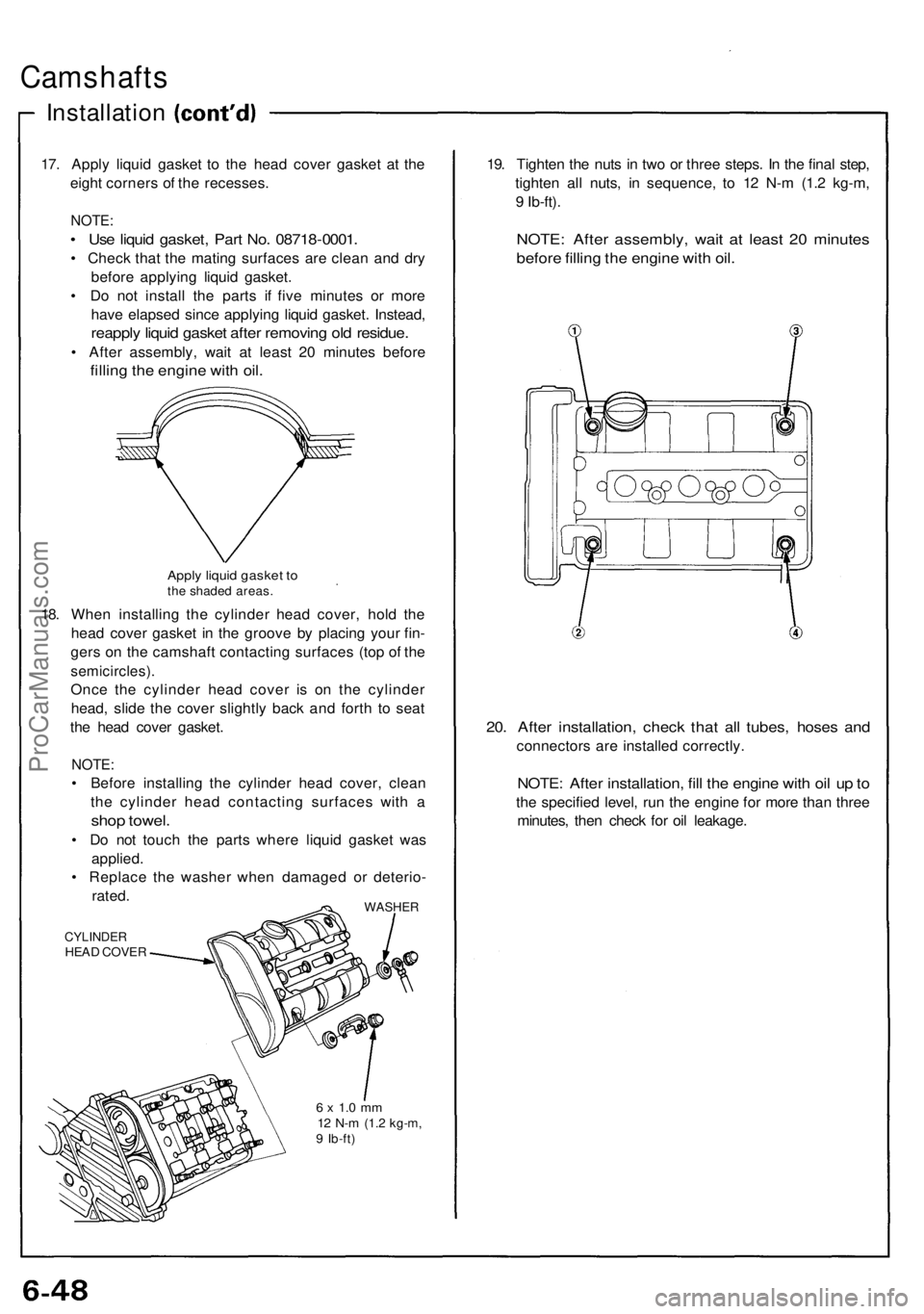
17. Appl y liqui d gaske t t o th e hea d cove r gaske t a t th e
eigh t corner s o f th e recesses .
NOTE:
• Us e liqui d gasket , Par t No . 0871 8-0001 .
• Chec k tha t th e matin g surface s ar e clea n an d dr y
befor e applyin g liqui d gasket .
• D o no t instal l th e part s i f fiv e minute s o r mor e
hav e elapse d sinc e applyin g liqui d gasket . Instead ,
reapply liqui d gaske t afte r removin g ol d residue .
• Afte r assembly , wai t a t leas t 2 0 minute s befor e
filling th e engin e wit h oil .
Appl y liqui d gaske t t oth e shade d areas .
18. Whe n installin g th e cylinde r hea d cover , hol d th e
hea d cove r gaske t i n th e groov e b y placin g you r fin -
ger s o n th e camshaf t contactin g surface s (to p o f th e
semicircles) .
Once th e cylinde r hea d cove r i s o n th e cylinde r
head , slid e th e cove r slightl y bac k an d fort h t o sea t
th e hea d cove r gasket .
NOTE:
• Befor e installin g th e cylinde r hea d cover , clea n
th e cylinde r hea d contactin g surface s wit h a
sho p towel .
• D o no t touc h th e part s wher e liqui d gaske t wa s
applied .
• Replac e th e washe r whe n damage d o r deterio -
rated .
WASHE R
CYLINDE RHEAD COVE R
6 x 1. 0 m m12 N- m (1. 2 kg-m ,9 Ib-ft )
19. Tighte n th e nut s i n tw o o r thre e steps . I n th e fina l step ,
tighte n al l nuts , i n sequence , t o 1 2 N- m (1. 2 kg-m ,
9 Ib-ft) .
NOTE : Afte r assembly , wai t a t leas t 2 0 minute s
before fillin g th e engin e wit h oil .
20. Afte r installation , chec k tha t al l tubes , hose s an d
connector s ar e installe d correctly .
NOTE: Afte r installation , fil l th e engin e wit h oi l u p to
th e specifie d level , ru n th e engin e fo r mor e tha n thre e
minutes , the n chec k fo r oi l leakage .
ProCarManuals.com
Page 161 of 1640

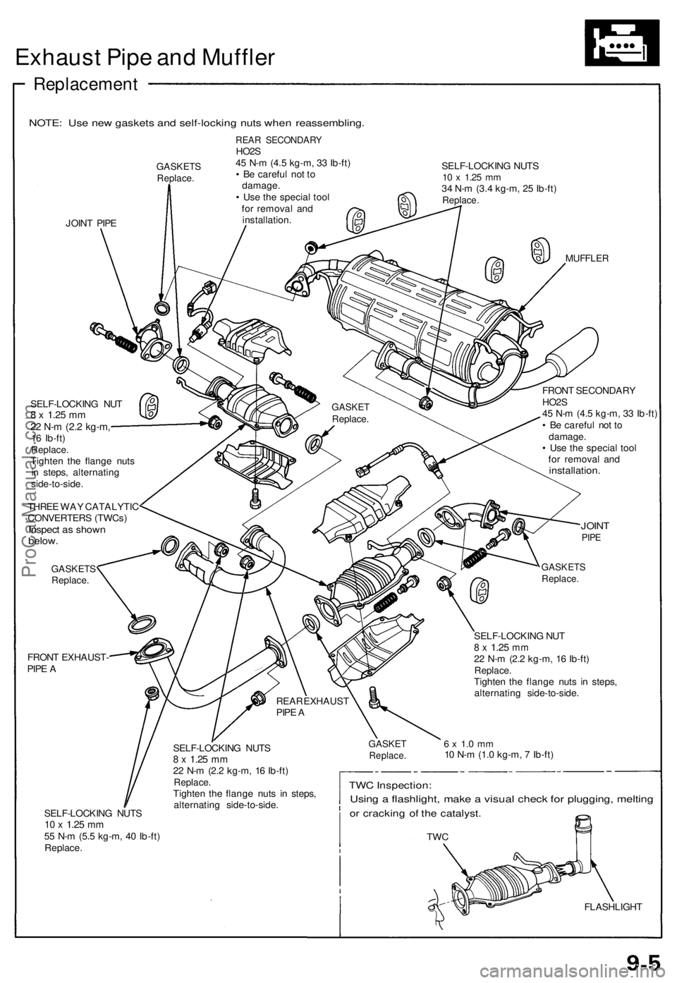
Exhaust Pip e an d Muffle r
Replacemen t
NOTE: Us e ne w gasket s an d self-lockin g nut s whe n reassembling .
GASKETSReplace.
JOINT PIP E
REA R SECONDAR YHO2S
4 5 N- m (4. 5 kg-m , 3 3 Ib-ft )
• B e carefu l no t t o
damage .
• Us e th e specia l too l
fo r remova l an d
installation . SELF-LOCKIN
G NUT S
10 x 1.2 5 mm34 N- m (3. 4 kg-m , 2 5 Ib-ft )Replace .
MUFFLE R
SELF-LOCKIN G NU T8 x 1.2 5 mm22 N- m (2. 2 kg-m ,16 Ib-ft )Replace .Tighten th e flang e nut s
i n steps , alternatin g
side-to-side .
THRE E WA Y CATALYTI C
CONVERTER S (TWCs )
Inspect a s show nbelow.
GASKET SReplace.
FRONT EXHAUST -
PIP E A FRON
T SECONDAR Y
HO2 S
4 5 N- m (4. 5 kg-m , 3 3 Ib-ft )
• B e carefu l no t t o
damage .
• Us e th e specia l too l
fo r remova l an d
installation .
JOINTPIPE
SELF-LOCKIN G NUT S10 x 1.2 5 mm55 N- m (5. 5 kg-m , 4 0 Ib-ft )
Replace . SELF-LOCKIN
G NUT S
8 x 1.2 5 mm22 N- m (2. 2 kg-m , 1 6 Ib-ft )Replace .Tighten th e flang e nut s i n steps ,
alternatin g side-to-side .
GASKETSReplace.
SELF-LOCKIN G NU T8 x 1.2 5 mm22 N- m (2. 2 kg-m , 1 6 Ib-ft )Replace .Tighten th e flang e nut s i n steps ,
alternatin g side-to-side .
6 x 1. 0 m m10 N- m (1. 0 kg-m , 7 Ib-ft )
TWC Inspection :
Using a flashlight , mak e a visua l chec k fo r plugging , meltin g
or crackin g o f th e catalyst .
TWC
FLASHLIGH T
REA
R EXHAUS T
PIP E A
GASKE TReplace .
GASKETReplace .
ProCarManuals.com
Page 210 of 1640
CAUTION:
• Puncturing the insulation on a wire can cause poor or intermittent electrical connections.
• Bring the tester probe into contact with the terminal from the connector side of wire harness connectors in the engine
compartment. For female connectors, just touch lightly with the tester probe and do not insert the probe.
RUBBER SEAL
TESTER PROBE
WIRE HARNESS
TERMINALProCarManuals.com