1991 ACURA NSX light
[x] Cancel search: lightPage 229 of 1640

PGM-FI Syste m
System Descriptio n
3. Fue l Cut-of f Contro l
• Durin g deceleratio n wit h th e throttl e valv e closed , curren t t o th e fue l injector s i s cu t of f t o improv e fue l econom y a t
speed s ove r 1,50 0 rpm .
• Fue l cut-of f actio n als o take s plac e whe n engin e spee d exceeds , 8,30 0 rpm , regardles s o f th e positio n o f th e throttl e
valve , t o protec t th e engin e fro m over-revving .
4 . A/ C Compresso r Clutc h Rela y
Whe n th e EC M receive s a deman d fo r coolin g fro m th e ai r conditionin g system , i t delay s th e compresso r fro m bein g
energized , an d enriche s th e mixtur e to assur e smoot h translatio n to th e A/ C mode .
5 . Evaporativ e Emissio n (EVAP ) Purg e Contro l Solenoi d Valv e
Whe n th e engin e coolan t temperatur e is belo w 153° F (67°C) , th e EC M control s th e EVA P purg e contro l solenoi d valv e
whic h cut s vacuu m to th e EVA P purg e contro l caniste r diaphragm .
6 . Intak e Ai r Bypas s (IAB ) Contro l Solenoi d Valv e
Whe n th e engin e spee d is belo w 4,80 0 rpm , th e IA B contro l solenoi d valv e is activate d b y a signa l fro m th e ECM . Intak e
ai r the n flow s throug h th e smalle r chamber , an d hig h torqu e is delivered . T o increas e ai r flo w a t engin e speed s highe r
tha n 4,80 0 rpm , th e solenoi d valv e is deactivate d b y th e ECM , an d th e intak e ai r flow s throug h th e large r chamber .
7 . Exhaus t Ga s Recirculatio n (EGR ) Contro l Solenoi d Valv e
Whe n th e EG R is require d fo r contro l o f oxide s o f nitroge n (NOx ) emissions , th e EC M supplie s groun d t o th e EG R
contro l solenoi d valv e whic h supplie s regulate d vacuu m to th e EG R valve .
EC M Fail-safe/Back-u p Function s
1 . Fail-Saf e Functio n
Whe n a n abnormalit y occur s i n a signa l fro m a sensor , th e EC M ignore s tha t signa l an d assume s a pre-programme d
valv e fo r tha t senso r tha t allow s th e engin e t o continu e t o run .
2 . Back-u p Functio n
Whe n a n abnormalit y occur s i n th e EC M itself , th e fue l injector s ar e controlle d b y a back-u p circui t independen t o f th e
syste m in orde r t o permi t minima l driving .
3 . Self-diagnosi s Functio n [Malfunctio n Indicato r Lam p (MIL) ]
Whe n a n abnormalit y occur s i n a signa l fro m a sensor , th e EC M light s th e MI L an d store s th e diagnosti c troubl e cod e
i n erasabl e memory . Whe n th e ignitio n i s initiall y turne d on , th e EC M supplie s groun d fo r th e MI L fo r tw o second s t o
chec k th e MI L bul b condition .
ProCarManuals.com
Page 230 of 1640
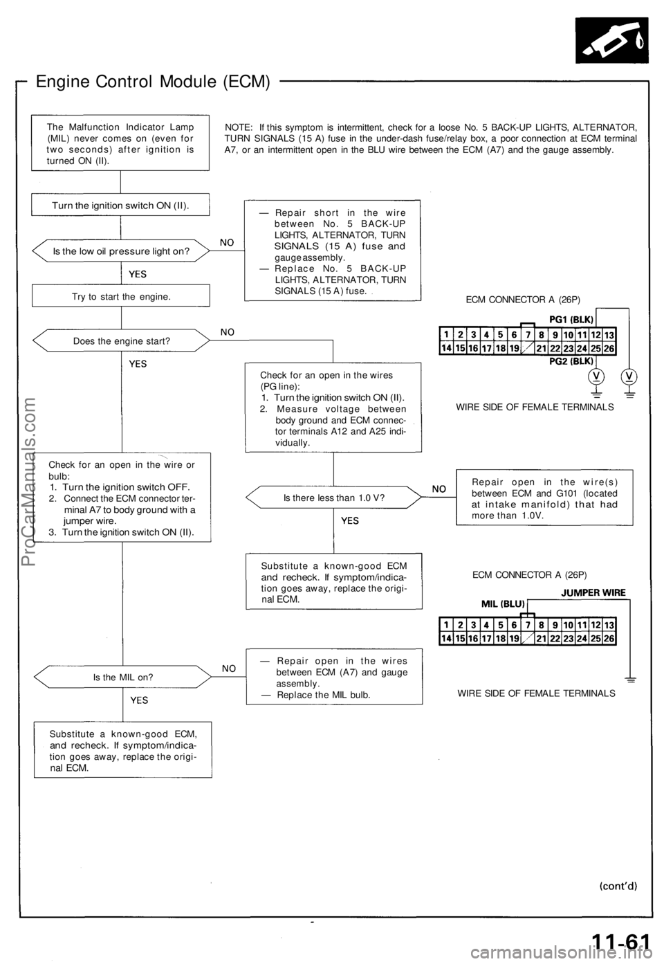
Engine Control Module (ECM)
NOTE: If this symptom is intermittent, check for a loose No. 5 BACK-UP LIGHTS, ALTERNATOR,
TURN SIGNALS (15 A) fuse in the under-dash fuse/relay box, a poor connection at ECM terminal
A7, or an intermittent open in the BLU wire between the ECM (A7) and the gauge assembly.
Is the low oil pressure light on?
Try to start the engine.
Does the engine start?
Check for an open in the wire or
bulb:
1. Turn the ignition switch OFF.
2. Connect the ECM connector ter-
minal A7 to body ground with a
jumper wire.
3. Turn the ignition switch ON (II).
Is the MIL on?
Substitute a known-good ECM,
and recheck. If symptom/indica-
tion goes away, replace the origi-
nal
ECM.
— Repair short in the wire
between No. 5 BACK-UP
LIGHTS, ALTERNATOR, TURN
SIGNALS (15 A) fuse and
gauge assembly.
— Replace No. 5 BACK-UP
LIGHTS, ALTERNATOR, TURN
SIGNALS (15 A) fuse.
ECM CONNECTOR A (26P)
Check for an open in the wires
(PG line):
1. Turn the ignition switch ON (II).
2. Measure voltage between
body ground and ECM connec-
tor terminals A12 and A25 indi-
vidually.
WIRE SIDE OF FEMALE TERMINALS
Is there less than 1.0 V?
Repair open in the wire(s)
between ECM and G101 (located
at intake manifold) that had
more than 1.0V.
— Repair open in the wires
between ECM (A7) and gauge
assembly.
— Replace the MIL bulb.
WIRE SIDE OF FEMALE TERMINALS
ECM CONNECTOR A (26P)
Substitute a known-good ECM
and recheck. If symptom/indica-
tion goes away, replace the origi-
nal
ECM.
Turn the ignition switch ON (II).
The Malfunction Indicator Lamp
(MIL) never comes on (even for
two seconds) after ignition is
turned ON (II).ProCarManuals.com
Page 238 of 1640
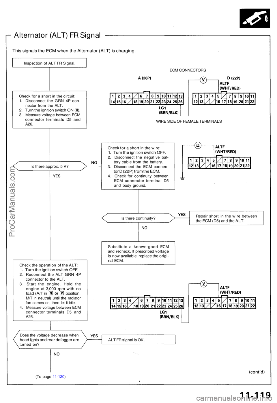
Alternator (ALT ) F R Signa l
This signal s th e EC M whe n th e Alternato r (ALT ) i s charging .
Inspection o f AL T F R Signal .
ECM CONNECTOR S
WIR E SID E O F FEMAL E TERMINAL S
Chec k fo r a shor t i n th e wire :
1. Tur n th e ignitio n switc h OFF .2. Disconnec t th e negativ e bat -
ter y cabl e fro m th e battery .
3 . Disconnec t th e EC M connec -
tor D (22P ) fro m th e ECM .4. Chec k fo r continuit y betwee n
EC M connecto r termina l D 5
an d bod y ground .
I
s ther e approx . 5 V ?
Chec
k fo r a shor t i n th e circuit :
1 . Disconnec t th e GR N 4 P con -
necto r fro m th e ALT .
2. Tur n th e ignitio n switc h O N (II) .3. Measur e voltag e betwee n EC M
connecto r terminal s D 5 an d
A26 .
Is ther e continuity ? Repai
r shor t i n th e wir e betwee nthe EC M (D5 ) and th e ALT .
Substitut e a known-goo d EC M
an d recheck . I f prescribe d voltag e
i s no w available , replac e th e origi -
nal ECM .Chec k th e operatio n o f th e ALT :1. Tur n th e ignitio n switc h OFF .2. Reconnec t th e AL T GR N 4 P
connecto r t o th e ALT .
3 . Star t th e engine . Hol d th e
engin e a t 3,00 0 rp m wit h n oloa d (A/ T in position ,M/T in neutral ) unti l th e radiato r
fa n come s on , the n le t i t idle .
4 . Measur e voltag e betwee n EC M
connecto r terminal s D 5 an d
A26.
Doe s th e voltag e decreas e whe nhead light s an d rea r defogge r ar eturne d on ? AL
T F R signa l i s OK .
(T o pag e 11-120 )
ProCarManuals.com
Page 245 of 1640
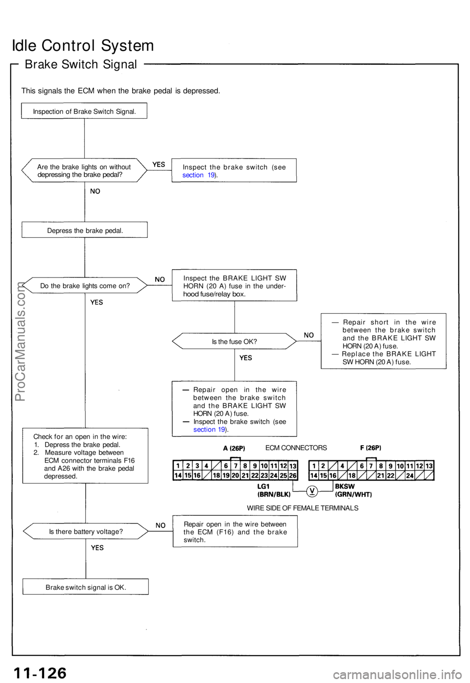
Idle Contro l Syste m
Brake Switc h Signa l
This signal s th e EC M whe n th e brak e peda l i s depressed .
Are th e brak e light s o n withou tdepressin g th e brak e pedal ?Inspec t th e brak e switc h (se e
sectio n 19 ).
Depres s th e brak e pedal .
D o th e brak e light s com e on ?
Is th e fus e OK ?
Chec k fo r a n ope n in th e wire :
1 . Depres s th e brak e pedal .
2 . Measur e voltag e betwee n
EC M connecto r terminal s F1 6
an d A2 6 wit h th e brak e peda l
depressed . —
Repai r shor t i n th e wir e
betwee n th e brak e switc h
an d th e BRAK E LIGH T S W
HOR N (2 0 A ) fuse .
— Replac e th e BRAK E LIGH T
S W HOR N (2 0 A ) fuse .
WIR E SID E O F FEMAL E TERMINAL S
I s ther e batter y voltage ? Repai
r ope n i n th e wir e betwee n
th e EC M (F16 ) an d th e brak e
switch .
Inspectio
n o f Brak e Switc h Signal .
Inspect th e BRAK E LIGH T S W
HORN (20 A ) fus e i n th e under -
hood fuse/rela y box .
Repai r ope n i n th e wir e
betwee n th e brak e switc h
an d th e BRAK E LIGH T S W
HOR N (2 0 A ) fuse .
Inspec t th e brak e switc h (se e
sectio n 19 ).
ECM CONNECTOR S
Brak e switc h signa l i s OK .
ProCarManuals.com
Page 247 of 1640
Idle Contro l Syste m
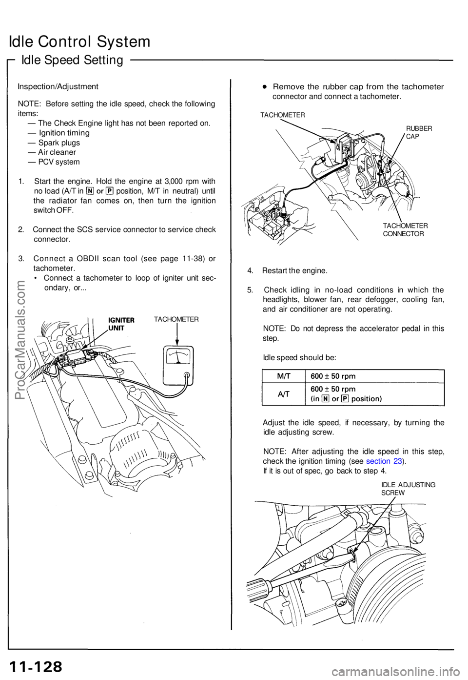
Idle Spee d Settin g
Inspection/Adjustmen t
NOTE: Befor e settin g th e idl e speed , chec k th e followin g
items :
— Th e Chec k Engin e ligh t ha s no t bee n reporte d on .
— Ignitio n timin g
— Spar k plug s
— Ai r cleane r
— PC V syste m
1 . Star t th e engine . Hol d th e engin e a t 3,00 0 rp m wit h
no loa d (A/ T in position , M/ T in neutral ) unti l
th e radiato r fa n come s on , the n tur n th e ignitio n
switc h OFF .
2 . Connec t th e SC S servic e connecto r t o servic e chec k
connector .
3. Connec t a OBDI I sca n too l (se e pag e 11-38 ) o r
tachometer .
• Connec t a tachomete r t o loo p o f ignite r uni t sec -
ondary , or.. .
TACHOMETE R
Remove th e rubbe r ca p fro m th e tachomete r
connector an d connec t a tachometer .
TACHOMETE R
RUBBERCAP
TACHOMETE RCONNECTOR
4. Restar t th e engine .
5 . Chec k idlin g i n no-loa d condition s i n whic h th e
headlights , blowe r fan , rea r defogger , coolin g fan ,
an d ai r conditione r ar e no t operating .
NOTE : D o no t depres s th e accelerato r peda l i n thi s
step .
Idl e spee d shoul d be :
Adjus t th e idl e speed , i f necessary , b y turnin g th e
idl e adjustin g screw .
NOTE : Afte r adjustin g th e idl e spee d i n thi s step ,
chec k th e ignitio n timin g (se e sectio n 23 ).
I f i t i s ou t o f spec , g o bac k t o ste p 4 .
IDL E ADJUSTIN GSCREW
ProCarManuals.com
Page 260 of 1640
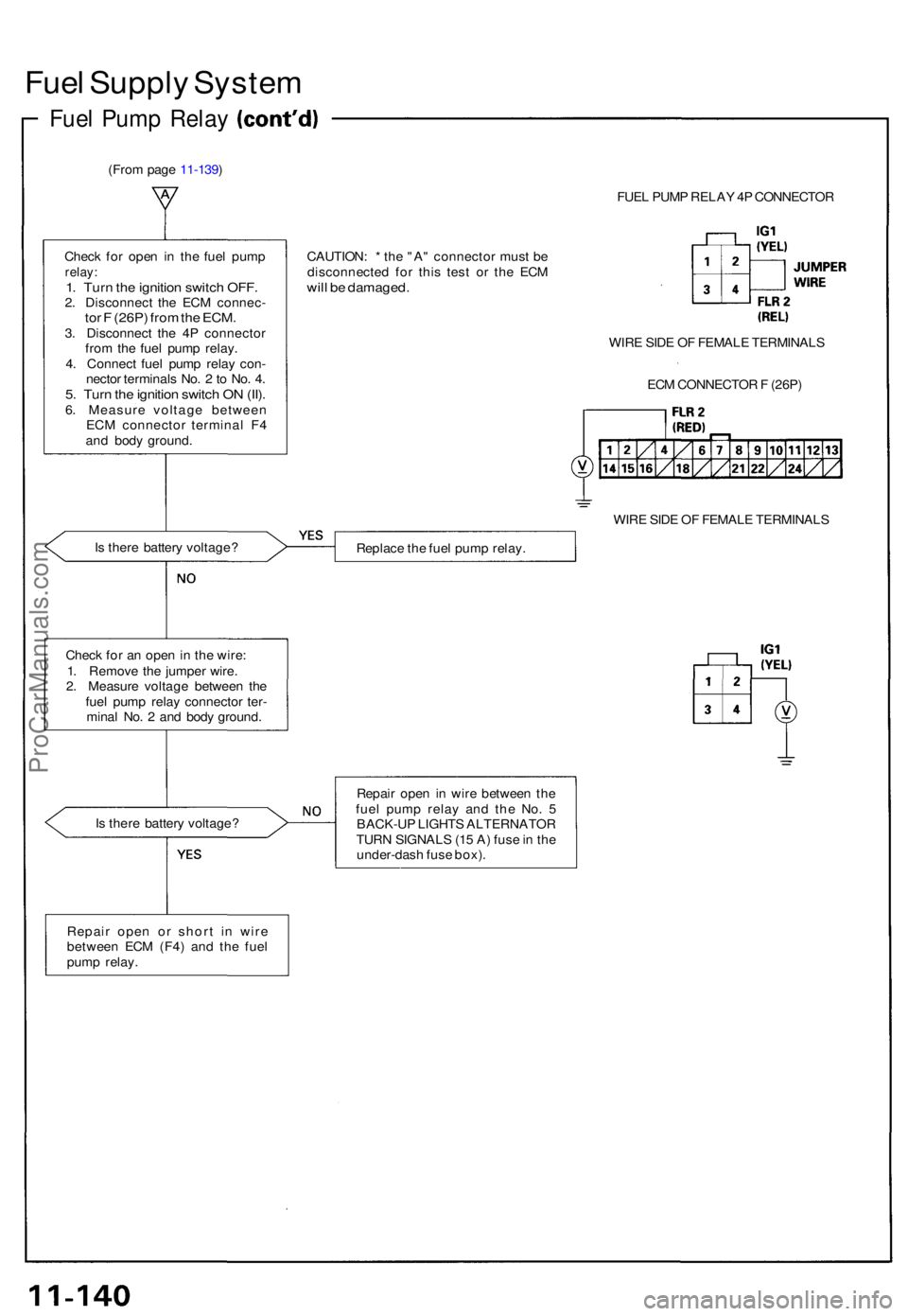
Fuel Suppl y Syste m
Fuel Pum p Rela y
(From pag e 11-139 )
FUEL PUM P RELA Y 4 P CONNECTO R
Chec k fo r ope n i n th e fue l pum p
relay:1. Tur n th e ignitio n switc h OFF .2. Disconnec t th e EC M connec -tor F (26P ) fro m th e ECM .3. Disconnec t th e 4 P connecto r
fro m th e fue l pum p relay .
4 . Connec t fue l pum p rela y con -
necto r terminal s No . 2 to No . 4 .
5. Tur n th e ignitio n switc h O N (II) .6. Measur e voltag e betwee n
EC M connecto r termina l F 4
an d bod y ground . CAUTION
: * th e "A " connecto r mus t b e
disconnecte d fo r thi s tes t o r th e EC M
will b e damaged .
WIRE SID E O F FEMAL E TERMINAL S
EC M CONNECTO R F (26P )
WIR E SID E O F FEMAL E TERMINAL S
I s ther e batter y voltage ?
Replace th e fue l pum p relay .
Chec k fo r a n ope n in th e wire :
1 . Remov e th e jumpe r wire .
2 . Measur e voltag e betwee n th e
fue l pum p rela y connecto r ter -
mina l No . 2 an d bod y ground .
I s ther e batter y voltage ? Repai
r ope n i n wir e betwee n th e
fue l pum p rela y an d th e No . 5
BACK-U P LIGHT S ALTERNATO R
TUR N SIGNAL S (1 5 A ) fus e in th e
under-das h fus e box) .
Repai r ope n o r shor t i n wir e
betwee n EC M (F4 ) an d th e fue l
pum p relay .
ProCarManuals.com
Page 268 of 1640
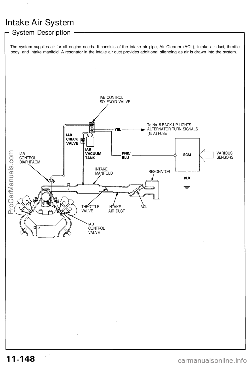
Intake Air System
System Description
The system supplies air for all engine needs. It consists of the intake air pipe, Air Cleaner (ACL), intake air duct, throttle
body, and intake manifold. A resonator in the intake air duct provides additional silencing as air is drawn into the system.
IAB CONTROL
SOLENOID VALVE
To No. 5 BACK-UP LIGHTS
ALTERNATOR TURN SIGNALS
(15 A) FUSE
IAB
CONTROL
DIAPHRAGM
IAB
CONTROL
VALVE
THROTTLE
VALVE
INTAKE
AIR DUCT
ACL
RESONATOR
VARIOUS
SENSORS
INTAKE
MANIFOLDProCarManuals.com
Page 271 of 1640
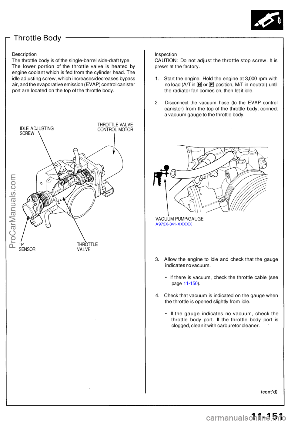
Throttle Bod y
Descriptio n
The throttl e bod y is o f th e single-barre l side-draf t type .
Th e lowe r portio n o f th e throttl e valv e i s heate d b y
engin e coolan t whic h is fe d fro m th e cylinde r head . Th e
idl e adjustin g screw , whic h increases/decrease s bypas s
air , an d th e evaporativ e emissio n (EVAP ) contro l caniste r
por t ar e locate d o n th e to p o f th e throttl e body .
IDLE ADJUSTIN GSCREW
THROTTL E VALV ECONTRO L MOTO R
TPSENSO RTHROTTL EVALVE
Inspectio n
CAUTION : D o no t adjus t th e throttl e sto p screw . I t i s
prese t a t th e factory .
1. Star t th e engine . Hol d th e engin e a t 3,00 0 rp m wit h
no loa d (A/ T in position , M/ T in neutral ) unti l
th e radiato r fa n come s on , the n le t i t idle .
2. Disconnec t th e vacuu m hos e (t o th e EVA P contro l
canister ) fro m th e to p o f th e throttl e body ; connec t
a vacuu m gaug e to th e throttl e body .
VACUU M PUMP/GAUG EA973X-04 1-XXXX X
3. Allo w th e engin e t o idl e an d chec k tha t th e gaug e
indicate s n o vacuum .
• I f ther e i s vacuum , chec k th e throttl e cabl e (se e
page 11-150 ).
4 . Chec k tha t vacuu m is indicate d o n th e gaug e whe n
th e throttl e is opene d slightl y fro m idle .
• I f th e gaug e indicate s n o vacuum , chec k th e
throttl e bod y port . I f th e throttl e bod y por t i s
clogged , clea n it wit h carbureto r cleaner .
ProCarManuals.com