Page 274 of 1640
Intake Air System
Intake Air Bypass (IAB) Control System
Description
Satisfactory power performance is achieved by closing and opening the intake air bypass (IAB) control valves. High torque
at low engine speed is achieved when the valves are closed, whereas high power at high engine speed is achieved when
the valves are opened.
INTAKE AIR BYPASS (IAB) CONTROL
SOLENOID VALVE ON
ENGINE SPEED IS ABOVE 4,800 rpm
OPEN: HIGH ENGINE SPEED
IAB CONTROL
SOLENOID
VALVE
To No. 5 BACK-UP LIGHTS
ALTERNATOR TURN SIGNALS
(15 A) FUSE
IAB
CONTROL
DIAPHRAGM
IAB
CONTROL
VALVE
CLOSED: LOW ENGINE SPEEDProCarManuals.com
Page 276 of 1640
Emission Contro l Syste m
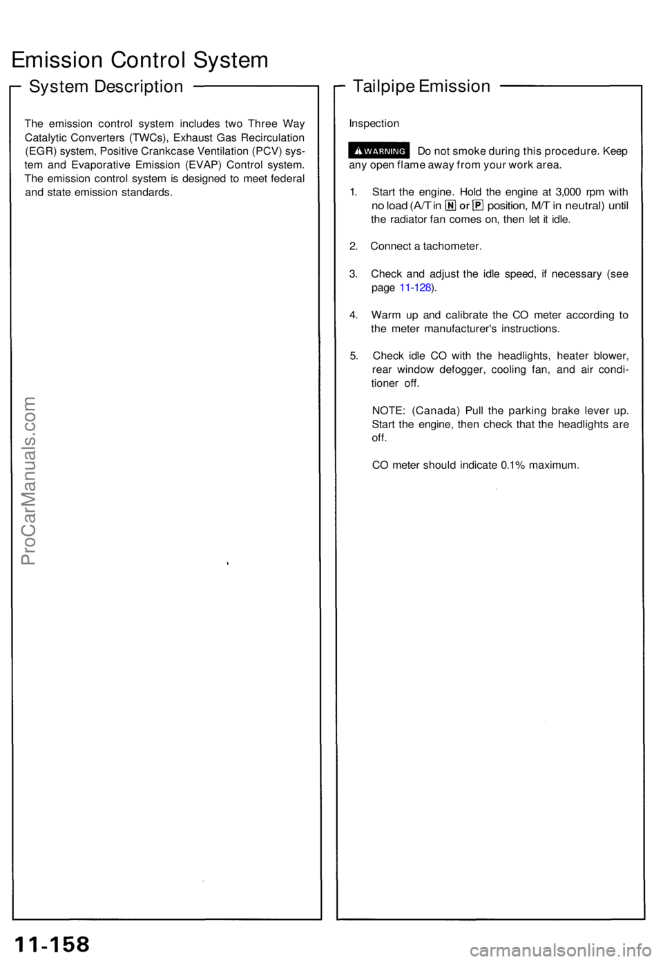
System Descriptio n
The emissio n contro l syste m include s tw o Thre e Wa y
Catalyti c Converter s (TWCs) , Exhaus t Ga s Recirculatio n
(EGR ) system , Positiv e Crankcas e Ventilatio n (PCV ) sys -
te m an d Evaporativ e Emissio n (EVAP ) Contro l system .
Th e emissio n contro l syste m is designe d t o mee t federa l
an d stat e emissio n standards .
Tailpipe Emissio n
Inspectio n
Do no t smok e durin g thi s procedure . Kee p
an y ope n flam e awa y fro m you r wor k area .
1 . Star t th e engine . Hol d th e engin e a t 3,00 0 rp m wit h
no loa d (A/ T in position , M/ T in neutral ) unti l
the radiato r fa n come s on , the n le t i t idle .
2 . Connec t a tachometer .
3 . Chec k an d adjus t th e idl e speed , i f necessar y (se e
pag e 11-128 ).
4 . War m u p an d calibrat e th e C O mete r accordin g t o
th e mete r manufacturer' s instructions .
5 . Chec k idl e C O wit h th e headlights , heate r blower ,
rea r windo w defogger , coolin g fan , an d ai r condi -
tione r off .
NOTE : (Canada ) Pul l th e parkin g brak e leve r up .
Star t th e engine , the n chec k tha t th e headlight s ar e
off.
CO mete r shoul d indicat e 0.1 % maximum .
ProCarManuals.com
Page 278 of 1640
Exhaust Ga s Recirculatio n (EGR ) Syste m
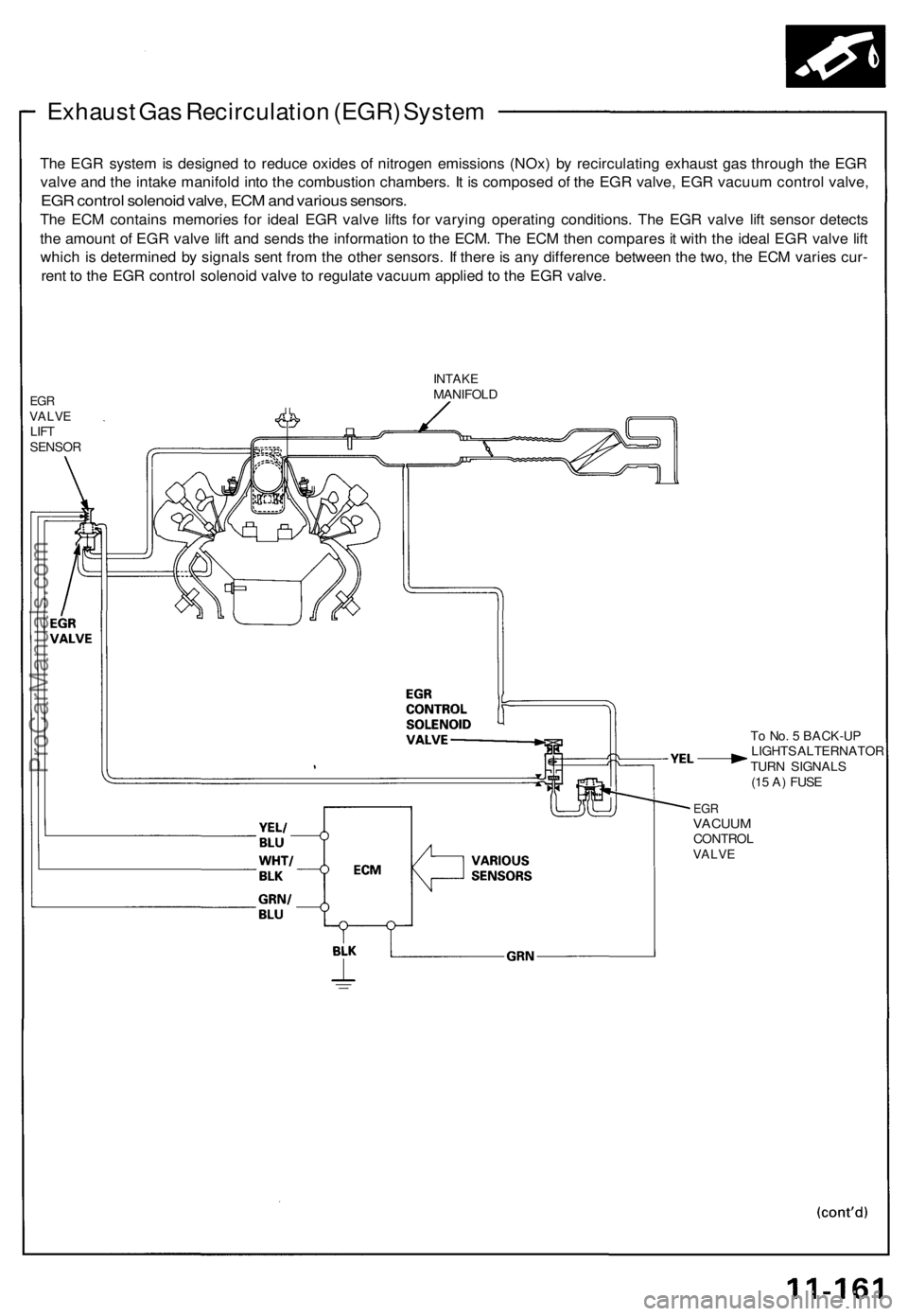
The EG R syste m is designe d t o reduc e oxide s o f nitroge n emission s (NOx ) b y recirculatin g exhaus t ga s throug h th e EG R
valv e an d th e intak e manifol d int o th e combustio n chambers . I t i s compose d o f th e EG R valve , EG R vacuu m contro l valve ,
EGR contro l solenoi d valve , EC M an d variou s sensors .
The EC M contain s memorie s fo r idea l EG R valv e lift s fo r varyin g operatin g conditions . Th e EG R valv e lif t senso r detect s
th e amoun t o f EG R valv e lif t an d send s th e informatio n t o th e ECM . Th e EC M the n compare s it wit h th e idea l EG R valv e lif t
whic h i s determine d b y signal s sen t fro m th e othe r sensors . I f ther e is an y differenc e betwee n th e two , th e EC M varie s cur -
ren t t o th e EG R contro l solenoi d valv e to regulat e vacuu m applie d t o th e EG R valve .
EGRVALV ELIFTSENSO R
INTAKEMANIFOL D
To No . 5 BACK-U P
LIGHT S ALTERNATO R
TUR N SIGNAL S
(1 5 A ) FUS E
EGRVACUU MCONTRO LVALVE
ProCarManuals.com
Page 279 of 1640
Emission Control System
Positive Crankcas e Ventilatio n (PCV ) Syste m
Descriptio n
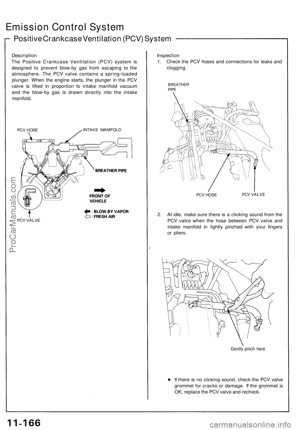
Th e Positiv e Crankcas e Ventilatio n (PCV ) syste m is
designe d t o preven t blow-b y ga s fro m escapin g t o th e
atmosphere . Th e PCV valve contain s a spring-loade d
plunger . Whe n th e engin e starts , th e plunge r i n th e PC V
valv e i s lifte d i n proportio n t o intak e manifol d vacuu m
an d th e blow-b y ga s i s draw n directl y int o th e intak e
manifold .
PCV HOS EINTAK E MANIFOL D
PCV VALV E
Inspectio n
1. Chec k th e PC V hose s an d connection s fo r leak s an d
clogging .
BREATHE RPIPE
PCV HOS E PC
V VALV E
2. A t idle , mak e sur e ther e i s a clickin g soun d fro m th e
PC V valv e whe n th e hos e betwee n PC V valv e an d
intak e manifol d i n lightl y pinche d wit h you r finger s
o r pliers .
Gently pinc h her e
If ther e i s n o clickin g sound , chec k th e PC V valv e
gromme t fo r crack s o r damage . I f th e gromme t i s
OK , replac e th e PC V valv e an d recheck .
ProCarManuals.com
Page 280 of 1640
Evaporative Emission (EVAP) Controls
Description
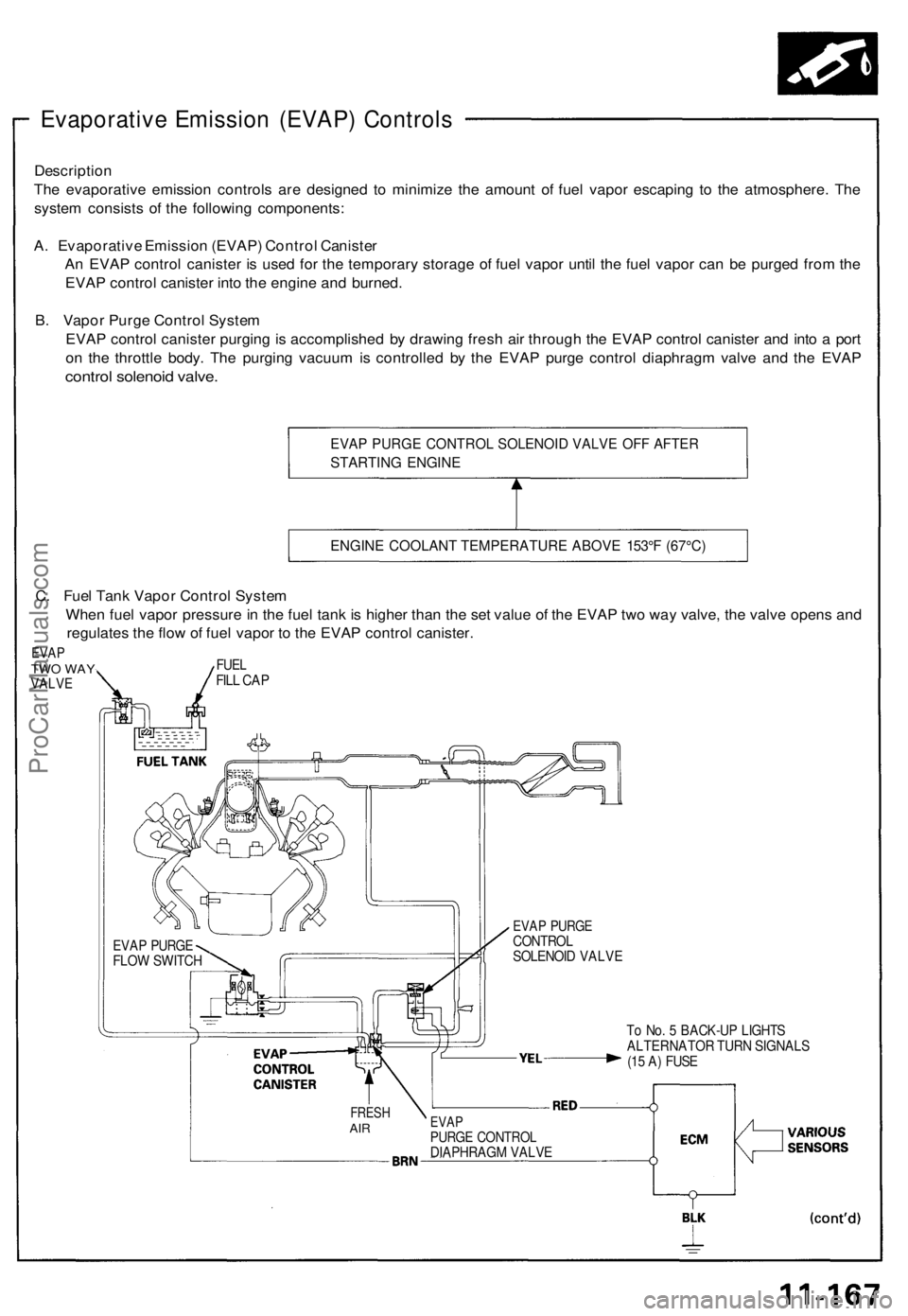
The evaporative emission controls are designed to minimize the amount of fuel vapor escaping to the atmosphere. The
system consists of the following components:
A. Evaporative Emission (EVAP) Control Canister
An EVAP control canister is used for the temporary storage of fuel vapor until the fuel vapor can be purged from the
EVAP control canister into the engine and burned.
B. Vapor Purge Control System
EVAP control canister purging is accomplished by drawing fresh air through the EVAP control canister and into a port
on the throttle body. The purging vacuum is controlled by the EVAP purge control diaphragm valve and the EVAP
control solenoid valve.
EVAP PURGE CONTROL SOLENOID VALVE OFF AFTER
STARTING ENGINE
ENGINE COOLANT TEMPERATURE ABOVE 153°F (67°C)
To No. 5 BACK-UP LIGHTS
ALTERNATOR TURN SIGNALS
(15 A) FUSE
FRESH
AIR
EVAP
PURGE CONTROL
DIAPHRAGM VALVE
EVAP PURGE
CONTROL
SOLENOID VALVE
EVAP PURGE
FLOW SWITCH
C. Fuel Tank Vapor Control System
When fuel vapor pressure in the fuel tank is higher than the set value of the EVAP two way valve, the valve opens and
regulates the flow of fuel vapor to the EVAP control canister.
EVAP
TWO WAY
VALVE
FUEL
FILL CAPProCarManuals.com
Page 304 of 1640
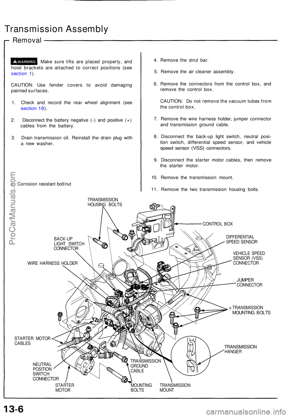
Transmission Assembl y
Removal
Make sur e lift s ar e place d properly , an d
hois t bracket s ar e attache d t o correc t position s (se e
sectio n 1 ).
CAUTION : Us e fende r cover s t o avoi d damagin g
painte d surfaces .
1 . Chec k an d recor d th e rea r whee l alignmen t (se e
sectio n 18 ).
2 . Disconnec t th e batter y negativ e (- ) an d positiv e (+ )
cable s fro m th e battery .
3 . Drai n transmissio n oil . Reinstal l th e drai n plu g wit h
a ne w washer .
Corrosio n resistan t bolt/nu t
4. Remov e th e stru t bar .
5 . Remov e th e ai r cleane r assembly .
6 . Remov e th e connector s fro m th e contro l box , an d
remov e th e contro l box .
CAUTION : D o no t remov e th e vacuu m tube s fro m
th e contro l box .
7 . Remov e th e wir e harnes s holder , jumpe r connecto r
an d transmissio n ground cable.
8 . Disconnec t th e back-u p ligh t switch , neutra l posi -
tio n switch , differentia l spee d sensor , an d vehicl e
speed senso r (VSS ) connectors .
9. Disconnec t th e starte r moto r cables , the n remov e
th e starte r motor .
10 . Remov e th e transmissio n mount .
11 . Remov e th e tw o transmissio n housin g bolts .
TRANSMISSIO N
HOUSIN G BOLT S
CONTROL BO X
BACK-U PLIGHT SWITC H
CONNECTO R
WIR E HARNES S HOLDE R
STARTER MOTOR
CABLES
NEUTRA L
POSITIO N
SWITCHCONNECTO R
DIFFERENTIA L
SPEE D SENSO R
VEHICL E SPEE D
SENSO R (VSS )
CONNECTO R
JUMPERCONNECTO R
TRANSMISSIO N
MOUNTING BOLT S
TRANSMISSIO NHANGER
STARTE RMOTOR MOUNTIN
G TRANSMISSIO N
BOLT S MOUN T
TRANSMISSIO
N
GROUN D
CABLE
ProCarManuals.com
Page 310 of 1640
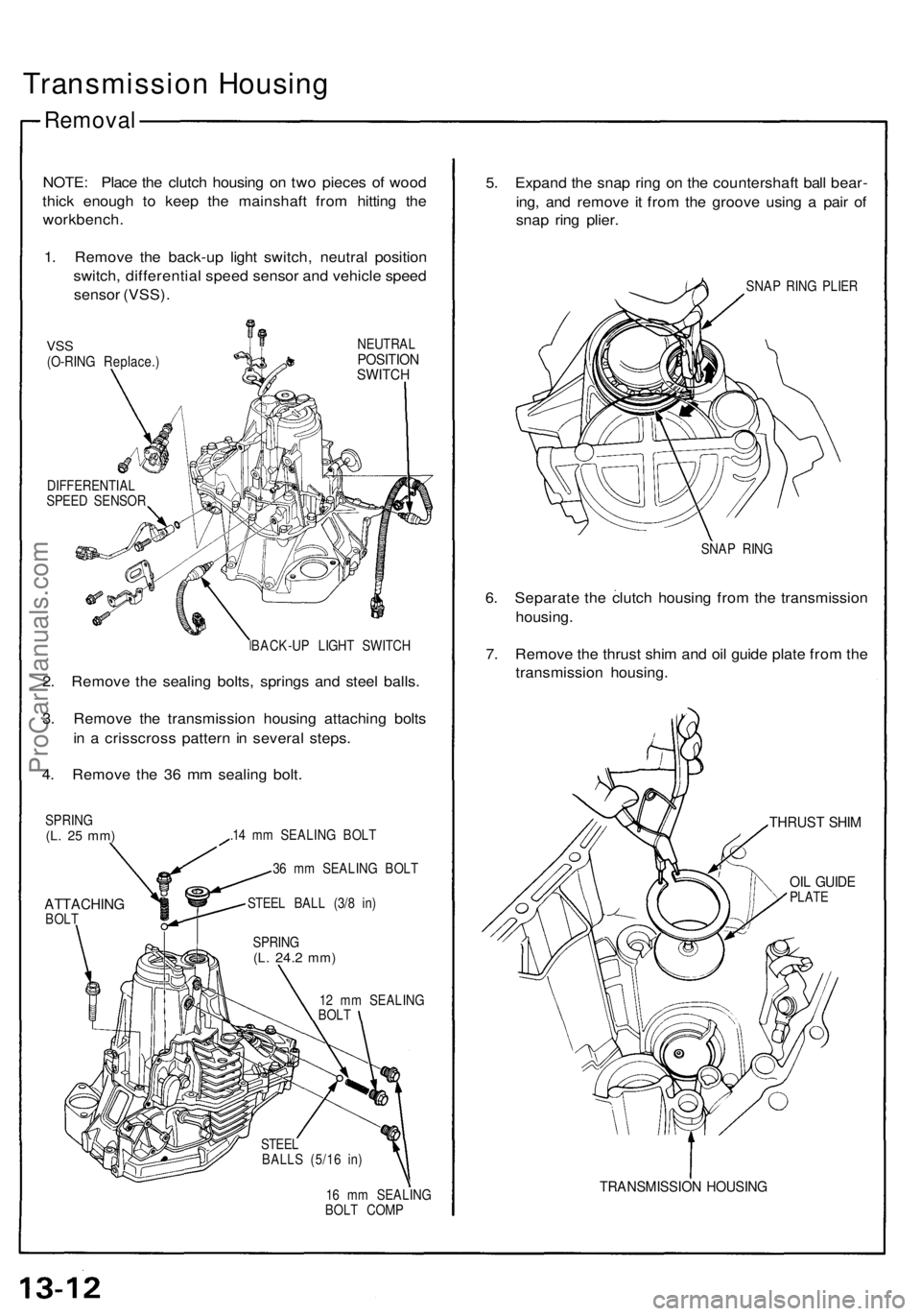
Transmission Housing
Removal
NOTE: Place the clutch housing on two pieces of wood
thick enough to keep the mainshaft from hitting the
workbench.
1. Remove the back-up light switch, neutral position
switch, differential speed sensor and vehicle speed
sensor (VSS).
VSS
(O-RING Replace.)
NEUTRAL
POSITION
SWITCH
DIFFERENTIAL
SPEED SENSOR
BACK-UP LIGHT SWITCH
2. Remove the sealing bolts, springs and steel balls.
3. Remove the transmission housing attaching bolts
in a crisscross pattern in several steps.
4. Remove the 36 mm sealing bolt.
SPRING
(L. 25 mm)
ATTACHING
BOLT
.14 mm SEALING BOLT
36 mm SEALING BOLT
STEEL BALL (3/8 in)
12 mm SEALING
BOLT
16 mm SEALING
BOLT COMP
5. Expand the snap ring on the countershaft ball bear-
ing, and remove it from the groove using a pair of
snap ring plier.
SNAP RING PLIER
SNAP RING
6. Separate the clutch housing from the transmission
housing.
7. Remove the thrust shim and oil guide plate from the
transmission housing.
THRUST SHIM
OIL GUIDE
PLATE
TRANSMISSION HOUSING
SPRING
(L.
24.2
mm)
STEEL
BALLS (5/16 in)ProCarManuals.com
Page 395 of 1640
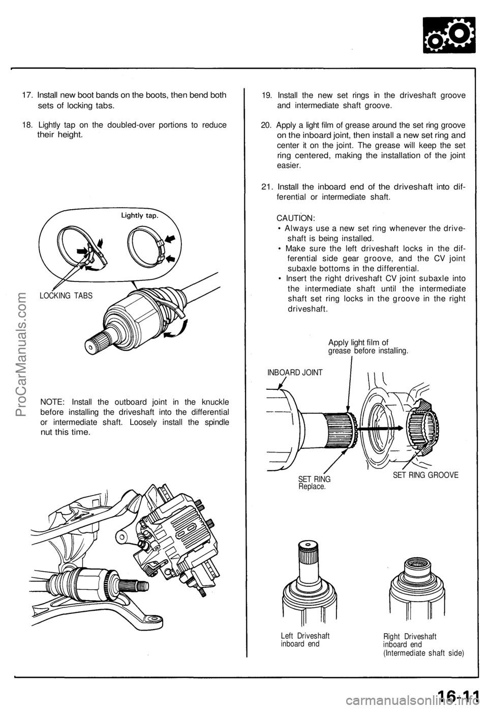
17. Install new boot bands on the boots, then bend both
sets of locking tabs.
18. Lightly tap on the doubled-over portions to reduce
their height.
NOTE: Install the outboard joint in the knuckle
before installing the driveshaft into the differential
or intermediate shaft. Loosely install the spindle
nut this time.
19. Install the new set rings in the driveshaft groove
and intermediate shaft groove.
20. Apply a light film of grease around the set ring groove
on the inboard joint, then install a new set ring and
center it on the joint. The grease will keep the set
ring centered, making the installation of the joint
easier.
21. Install the inboard end of the driveshaft into dif-
ferential or intermediate shaft.
CAUTION:
• Always use a new set ring whenever the drive-
shaft is being installed.
• Make sure the left driveshaft locks in the dif-
ferential side gear groove, and the CV joint
subaxle bottoms in the differential.
• Insert the right driveshaft CV joint subaxle into
the intermediate shaft until the intermediate
shaft set ring locks in the groove in the right
driveshaft.
Apply light film of
grease before installing.
INBOARD JOINT
SET RING
Replace.
SET RING GROOVE
Left Driveshaft
inboard end
Right Driveshaft
inboard end
(Intermediate shaft side)
LOCKING TABSProCarManuals.com