1991 ACURA NSX light
[x] Cancel search: lightPage 523 of 1640
Anti-lock Brak e Syste m (ABS ) Descriptio n
Features/Construction/Operatio n (cont'd )
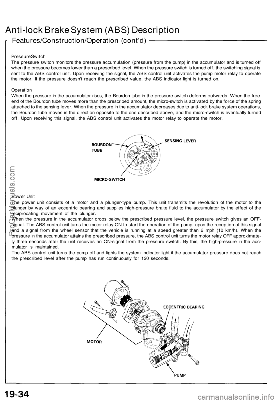
Pressur e Switc h
Th e pressur e switc h monitor s th e pressur e accumulatio n (pressur e fro m th e pump ) i n th e accumulato r an d is turne d of f
whe n th e pressur e become s lowe r tha n a prescribe d level . Whe n th e pressur e switc h is turne d off , th e switchin g signa l i s
sen t t o th e AB S contro l unit . Upo n receivin g th e signal , th e AB S contro l uni t activate s th e pum p moto r rela y t o operat e
th e motor . I f th e pressur e doesn' t reac h th e prescribe d value , th e AB S indicato r ligh t i s turne d on .
Operatio n
When th e pressur e in th e accumulato r rises , th e Bourdo n tub e in th e pressur e switc h deform s outwards . Whe n th e fre e
end o f th e Bourdo n tub e move s mor e tha n th e prescribe d amount , th e micro-switc h is activate d b y th e forc e o f th e sprin g
attache d t o th e sensin g lever . Whe n th e pressur e in th e accumulato r decrease s du e to anti-loc k brak e syste m operations ,
th e Bourdo n tub e move s i n th e directio n opposit e t o th e on e describe d above , an d th e micro-switc h is eventuall y turne d
off . Upo n receivin g thi s signal , th e AB S contro l uni t activate s th e moto r rela y t o operat e th e motor .
Powe r Uni t
Th e powe r uni t consist s o f a moto r an d a plunger-typ e pump . Thi s uni t transmit s th e revolutio n o f th e moto r t o th e
plunge r b y wa y o f a n eccentri c bearin g an d supplie s high-pressur e brak e flui d t o th e accumulato r b y th e effec t o f th e
reciprocatin g movemen t o f th e plunger .
Whe n th e pressur e i n th e accumulato r drop s belo w th e prescribe d pressur e level , th e pressur e switc h give s a n OFF -
signal . Th e AB S contro l uni t turn s th e moto r rela y O N to star t th e operatio n o f th e pump , upo n th e receptio n o f thi s signa l
an d a signa l fro m th e whee l senso r tha t th e vehicl e i s runnin g a t a spee d greate r tha n 6 mp h (1 0 km/h) . Whe n th e
pressur e in th e accumulato r attain s th e prescribe d pressure , th e AB S contro l uni t turn s th e moto r rela y OF F approximate -
l y thre e second s afte r th e uni t receive s a n ON-signa l fro m th e pressur e switch . B y this , th e high-pressur e i n th e acc -
mulato r i s maintained .
Th e AB S contro l uni t turn s th e pum p of f an d light s th e syste m indicato r ligh t i f th e accumulato r pressur e doe s no t reac h
th e prescribe d leve l afte r th e pum p ha s ru n continuousl y fo r 12 0 seconds .
ProCarManuals.com
Page 527 of 1640
ALB Checke r
Function Tes t
NOTE :
• Th e AL B checke r i s designe d t o confir m prope r
operatio n of the anti-loc k brak e syste m (ABS ) b y
simulatin g eac h syste m functio n an d operatin g con -
dition . Befor e usin g th e checker , confir m tha t th e
anti-loc k brak e syste m (ABS ) indicato r ligh t i s no t in -
dicatin g som e othe r proble m wit h th e system . Th e
light shoul d g o o n whe n th e ignitio n i s firs t turne d o n
an d the n g o of f an d sta y of f on e secon d afte r th e
engin e i s started .
• Th e checke r shoul d b e use d throug h modes ,
1-5, t o
confir m prope r operatio n of the system , i n an y on e
of th e followin g situations :
Afte r replacin g an y AB S component .
Afte r replacin g o r bleedin g th e syste m flui d ( 0
mod e no t necessary) .
Afte r an y bod y o r suspensio n repai r tha t ma y
hav e affecte d th e sensor s o r thei r wiring .
• Th e procedur e fo r mode s
1-5 ar e o n thi s pag e an d
19-42 , mod e 0 (whee l senso r signal ) i s o n pag e
19-43 .
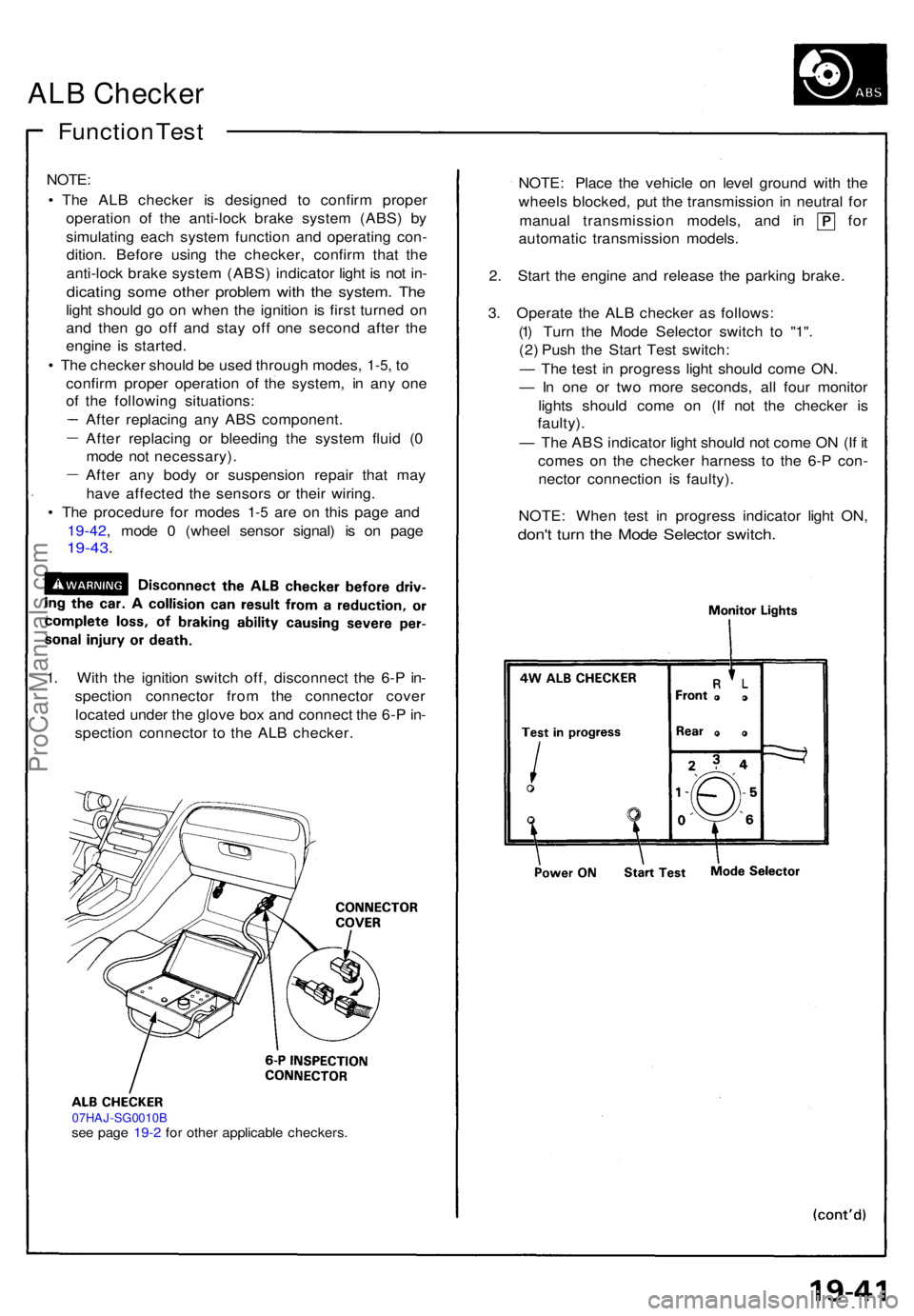
1. Wit h th e ignitio n switc h off , disconnec t th e 6- P in -
spectio n connecto r fro m th e connecto r cove r
locate d unde r th e glov e bo x an d connec t th e 6- P in -
spectio n connecto r t o th e AL B checker .
07HAJ-SG0010Bsee pag e 19- 2 fo r othe r applicabl e checkers .
NOTE: Plac e th e vehicl e o n leve l ground with th e
wheel s blocked , pu t th e transmissio n i n neutra l fo r
manua l transmissio n models , an d i n fo r
automati c transmissio n models .
2 . Star t th e engin e an d releas e th e parkin g brake .
3 . Operat e th e AL B checke r a s follows :
(1 ) Tur n th e Mod e Selecto r switc h t o "1" .
(2 ) Pus h th e Star t Tes t switch :
— Th e tes t i n progres s ligh t shoul d com e ON .
— In on e o r tw o mor e seconds , al l fou r monito r
light s shoul d com e o n (I f no t th e checke r i s
faulty) .
— Th e AB S indicato r ligh t shoul d no t com e O N (I f i t
come s o n th e checke r harnes s t o th e 6- P con -
necto r connectio n i s faulty) .
NOTE : Whe n tes t i n progres s indicato r ligh t ON ,
don't tur n th e Mod e Selecto r switch .
ProCarManuals.com
Page 528 of 1640
ALB Checker
Function Test (cont'd)
4. Turn the Mode Selector switch further to "2". 5. Depress the brake pedal firmly and push the Start
Test switch
The ABS indicator light should not go on while the
Test in Progress light is ON. There should bekickback on the brake pedal. If not as described, go
to troubleshooting, page 19-44 ('91-'92) ('93-'96).
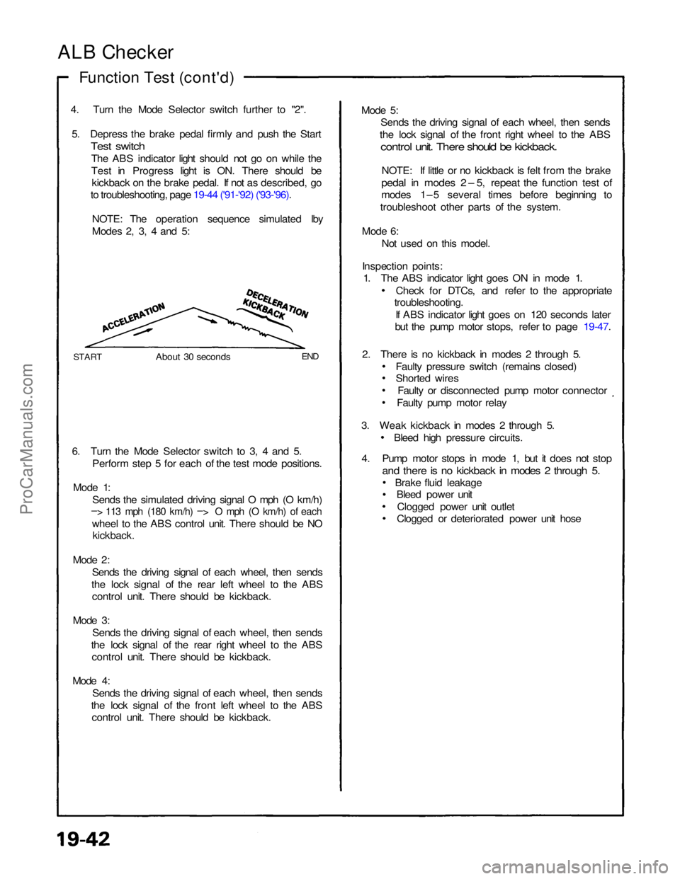
NOTE: The operation sequence simulated lby
Modes 2, 3, 4 and 5:
START
About 30 seconds
END
6. Turn the Mode Selector switch to 3, 4 and 5. Perform step 5 for each of the test mode positions.
Mode 1: Sends the simulated driving signal O mph (O km/h)
– > 113 mph (180 km/h) –
>
O mph (O km/h) of each
wheel to the ABS control unit. There should be NO
kickback.
Mode 2: Sends the driving signal of each wheel, then sends
the lock signal of the rear left wheel to the ABS control unit. There should be kickback.
Mode 3: Sends the driving signal of each wheel, then sends
the lock signal of the rear right wheel to the ABS control unit. There should be kickback.
Mode 4: Sends the driving signal of each wheel, then sends
the lock signal of the front left wheel to the ABS control unit. There should be kickback. Mode 5:
Sends the driving signal of each wheel, then sends
the lock signal of the front right wheel to the ABS
control unit. There should be kickback.
NOTE: If little or no kickback is felt from the brake
pedal in modes 2 – 5, repeat the function test of
modes 1–5 several times before beginning to
troubleshoot other parts of the system.
Mode 6: Not used on this model.
Inspection points: 1. The ABS indicator light goes ON in mode 1.
Check for DTCs, and refer to the appropriate
troubleshooting.
If ABS indicator light goes on 120 seconds later
but the pump motor stops, refer to page 19-47.
2. There is no kickback in modes 2 through 5. Faulty pressure switch (remains closed)
Shorted wiresFaulty or disconnected pump motor connector
Faulty pump motor relay
3. Weak kickback in modes 2 through 5. Bleed high pressure circuits.
4. Pump motor stops in mode 1, but it does not stop
and there is no kickback in modes 2 through 5.
Brake fluid leakageBleed power unit
Clogged power unit outlet
Clogged or deteriorated power unit hoseProCarManuals.com
Page 529 of 1640
Wheel Sensor Signal Confirmation
NOTE: Us e th e AL B checke r (mod e 0 ) t o confir m pro -
pe r whee l senso r operation .
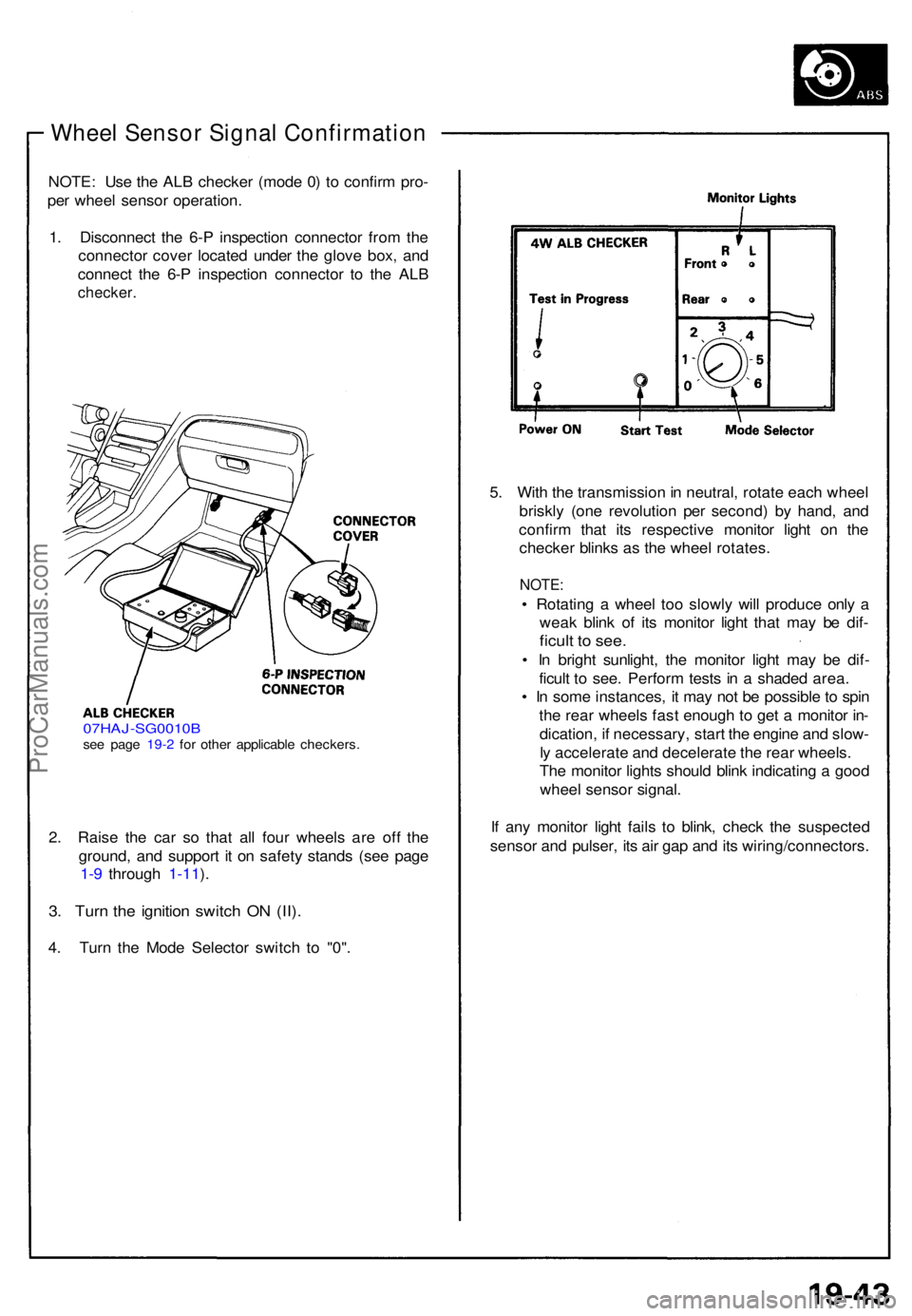
1 . Disconnec t th e 6- P inspectio n connecto r fro m th e
connecto r cove r locate d unde r th e glov e box , an d
connec t th e 6- P inspectio n connecto r t o th e AL B
checker .
07HAJ-SG0010 Bsee pag e 19- 2 fo r othe r applicabl e checkers .
2. Rais e th e ca r s o tha t al l fou r wheel s ar e of f th e
ground , an d suppor t i t o n safet y stand s (se e pag e
1-9 throug h 1-11 ).
3 . Tur n th e ignitio n switc h O N (II) .
4. Tur n th e Mod e Selecto r switc h t o "0" . 5
. Wit h th e transmissio n in neutral , rotat e eac h whee l
briskl y (on e revolutio n pe r second ) b y hand , an d
confir m tha t it s respectiv e monito r ligh t o n th e
checke r blink s a s th e whee l rotates .
NOTE:
• Rotatin g a whee l to o slowl y wil l produc e onl y a
wea k blin k o f it s monito r ligh t tha t ma y b e dif -
ficul t t o see .
• I n brigh t sunlight , th e monito r ligh t ma y b e dif -
ficul t t o see . Perfor m test s i n a shade d area .
• I n som e instances , i t ma y no t b e possibl e to spi n
th e rea r wheel s fas t enoug h t o ge t a monito r in -
dication , i f necessary , star t th e engin e an d slow -
l y accelerat e an d decelerat e th e rea r wheels .
Th e monito r light s shoul d blin k indicatin g a goo d
whee l senso r signal .
I f an y monito r ligh t fail s t o blink , chec k th e suspecte d
senso r an d pulser , it s ai r ga p an d it s wiring/connectors .
ProCarManuals.com
Page 531 of 1640
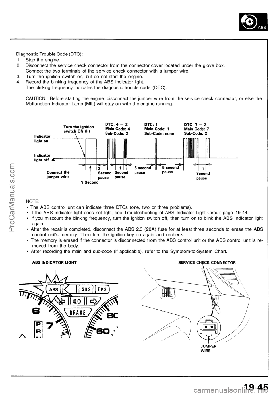
Diagnostic Trouble Code (DTC):
1. Stop the engine.
2. Disconnect the service check connector from the connector cover located under the glove box.
Connect the two terminals of the service check connector with a jumper wire.
3. Turn the ignition switch on, but do not start the engine.
4. Record the blinking frequency of the ABS indicator light.
The blinking frequency indicates the diagnostic trouble code (DTC).
CAUTION: Before starting the engine, disconnect the jumper wire from the service check connector, or else the
Malfunction Indicator Lamp (MIL) will stay on with the engine running.
NOTE:
• The ABS control unit can indicate three DTCs (one, two or three problems).
• If the ABS indicator light does not light, see Troubleshooting of ABS Indicator Light Circuit page 19-44.
• If you miscount the blinking frequency, turn the ignition switch off, then turn on to blink the ABS indicator light
again.
• After the repair is completed, disconnect the ABS 2,3 (20A) fuse for at least three seconds to erase the ABS
control unit's memory. Then turn the ignition key on again and recheck.
• The memory is erased if the connector is disconnected from the ABS control unit or the ABS control unit is re-
moved from the body.
• After recording the main and sub-code (if applicable), refer to the Symptom-to-System Chart.ProCarManuals.com
Page 546 of 1640
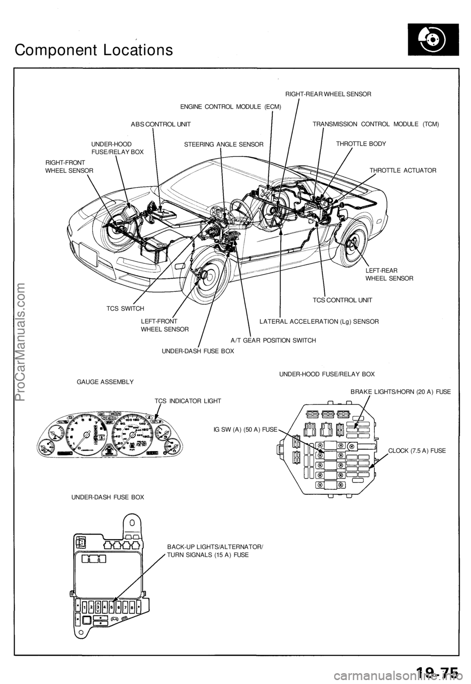
Component Location s
ENGINE CONTRO L MODUL E (ECM )
ABS CONTRO L UNI T
UNDER-HOO D
FUSE/RELA Y BO X
RIGHT-FRON T
WHEE L SENSO R RIGHT-REA
R WHEE L SENSO R
TRANSMISSIO N CONTRO L MODUL E (TCM )
THROTTL E BOD Y
THROTTL E ACTUATO R
LEFT-REARWHEEL SENSO R
TC S SWITC H
LEFT-FRON T
WHEE L SENSO R
TCS CONTRO L UNI T
LATERAL ACCELERATION (Lg) SENSOR
A/T GEA R POSITIO N SWITC H
UNDER-DAS H FUS E BO X
GAUG E ASSEMBL Y UNDER-HOO
D FUSE/RELA Y BO X
BRAK E LIGHTS/HOR N (2 0 A ) FUS E
TC S INDICATO R LIGH T
I G S W (A ) (5 0 A ) FUS E
UNDER-DAS H FUS E BO X CLOC
K (7. 5 A ) FUS E
BACK-U P LIGHTS/ALTERNATOR /
TUR N SIGNAL S (1 5 A ) FUS E
STEERIN
G ANGL E SENSO R
ProCarManuals.com
Page 553 of 1640
Troubleshooting
TCS Indicato r Ligh t
Temporar y Drivin g Conditions :
1 . Th e TC S indicato r ligh t wil l com e o n an d th e contro l uni t memorize s th e Diagnosti c Troubl e Cod e (DTC ) unde r certai n
temporar y conditions :
• Th e spar e tir e is installed , o r a tir e o f th e imprope r siz e is installed .
• Th e tir e pressure s ar e no t correct .
2 . I f th e TC S indicato r ligh t doe s no t com e bac k o n afte r correctin g th e tir e o r tir e pressur e problem , th e TC S syste m is
OK .
3. Remov e th e CLOC K (7. 5 A ) fus e fo r a t leas t thre e second s to clea r th e DT C fro m th e TC S contro l uni t memory .
NOTE : Disconnectin g th e CLOC K fus e als o cancel s th e radi o prese t station s an d th e cloc k setting . Mak e not e o f th e
radi o preset s befor e removin g th e fus e s o yo u ca n rese t them .
TC S Diagnosti c Troubl e Cod e (DTC ) Indication :
1 . Sto p th e engine .
2 . Tur n th e ignitio n switc h O N (II) , an d confir m tha t th e TC S indicato r ligh t come s on .
3 . Tur n th e ignitio n switc h off .
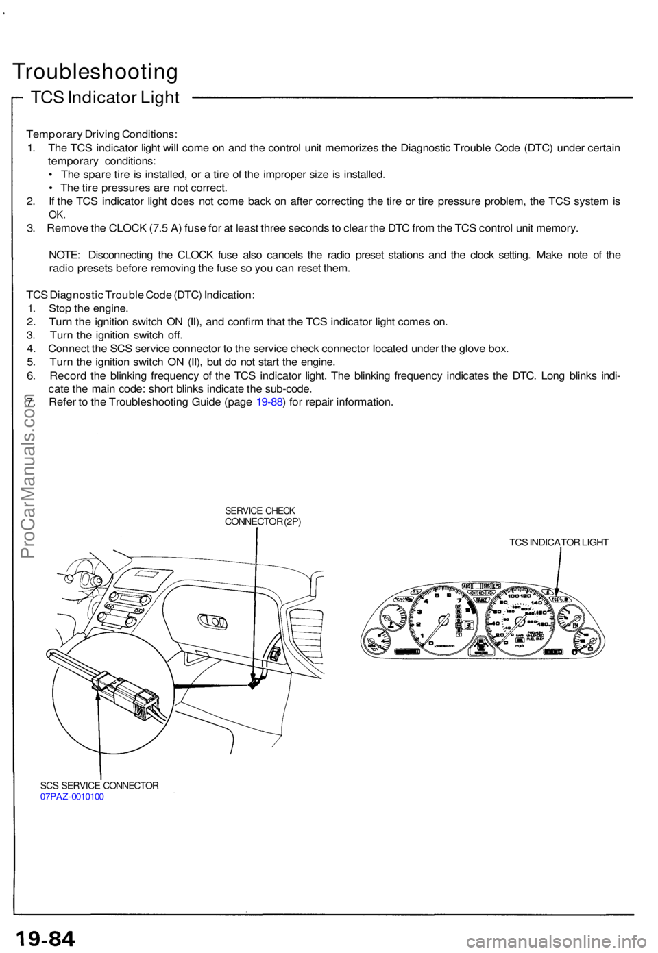
4 . Connec t th e SC S servic e connecto r t o th e servic e chec k connecto r locate d unde r th e glov e box .
5 . Tur n th e ignitio n switc h O N (II) , bu t d o no t star t th e engine .
6 . Recor d th e blinkin g frequenc y o f th e TC S indicato r light . Th e blinkin g frequenc y indicate s th e DTC . Lon g blink s indi -
cat e th e mai n code : shor t blink s indicat e th e sub-code .
7 . Refe r t o th e Troubleshootin g Guid e (pag e 19-88 ) fo r repai r information .
SERVICE CHEC KCONNECTO R (2P )
TCS INDICATO R LIGH T
SCS SERVIC E CONNECTO R07PAZ-001010 0
ProCarManuals.com
Page 558 of 1640
Steering angle sensor system check
1. Start the engine,
2. Push the TCS switch three times within three seconds.
NOTE: Always maintain the same number of rota-
tions.
3. Turn the steering wheel slowly from left to right more than 1.5 turns.
NOTE:
Start checking after the steering wheel moves at
least 1.5 turns from right to left.
Turn the steering wheel slowly, no faster than
one turn in four seconds.
4. Push the TCS switch twice within three seconds. NOTE: Always maintain the same number of rota-
tions.
5. Return the steering wheel to the left side slowly, and check the number of times the TCS indicator light
flashes after the wheel has moved approximately
one turn.
NOTE:
Start the check from the beginning when the steer-ing wheel moves at least one turn from left to
right, Turn the steering wheel slowly, no faster than one
turn in four seconds.
Standard number of times the TCS indicator light
flashes:
Manual Transmission: 5 times
Automatic Transmission: 2 times
6. If there is an abnormality, check the troubleshooting flowchart (see page 19-98('91-'93)('94-'96)
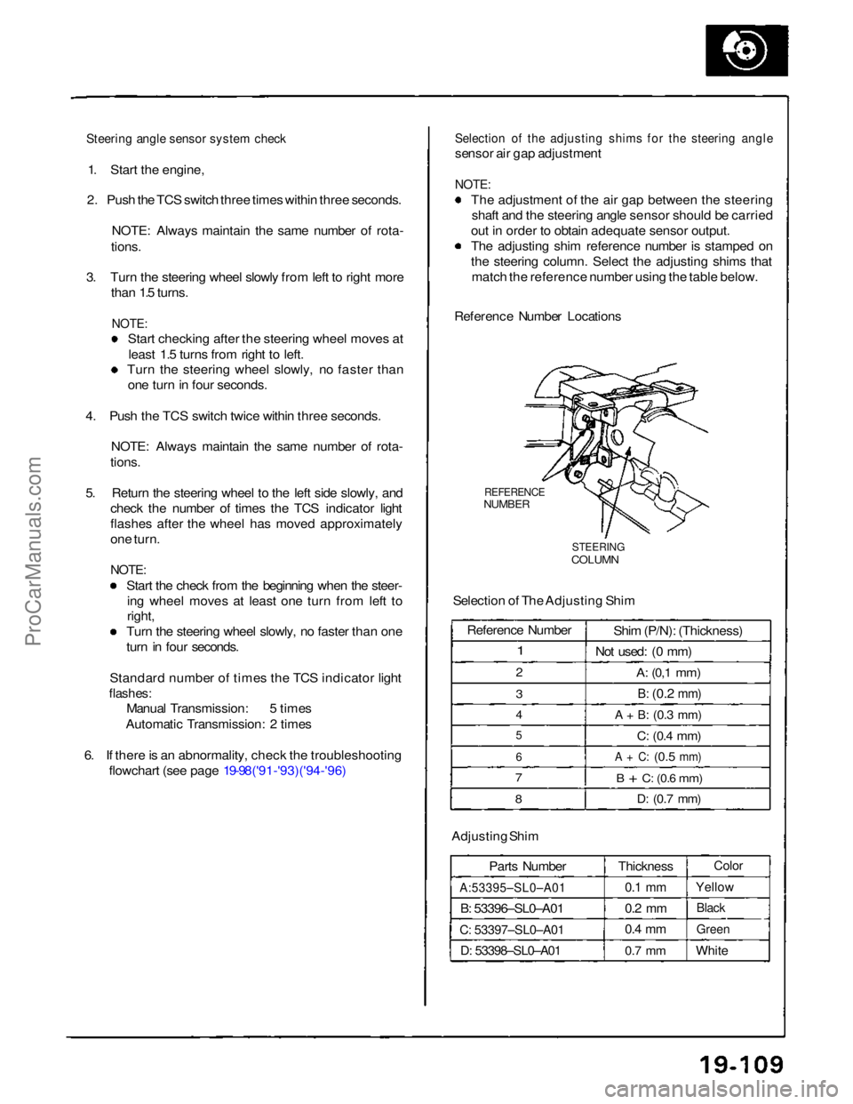
Selection of the adjusting shims for the steering angle
sensor air gap adjustment
NOTE:
The adjustment of the air gap between the steeringshaft and the steering angle sensor should be carried
out in order to obtain adequate sensor output.
The adjusting shim reference number is stamped on
the steering column. Select the adjusting shims that match the reference number using the table below.
Reference Number Locations
REFERENCE
NUMBER
STEERING
COLUMN
Selection of The Adjusting Shim
Adjusting Shim Parts Number
A:53395–SL0–A01
B: 53396–SL0–A01
C: 53397–SL0–A01
D: 53398–SL0–A01
Thickness
0.1 mm
0.2 mm
0.4 mm
0.7 mm
Color
Yellow
Black
Green
White
Reference Number
1
2
3
4
5
6
7
8
Shim (P/N): (Thickness)
Not used: (0 mm)
A:
(0,1
mm)
B:
(0.2
mm)
A + B:
(0.3
mm)
C:
(0.4
mm)
A + C:
(0.5
mm)
B + C:
(0.6
mm)
D:
(0.7
mm)ProCarManuals.com