Page 595 of 1640
Headliner/lnterior Trim
Replacement
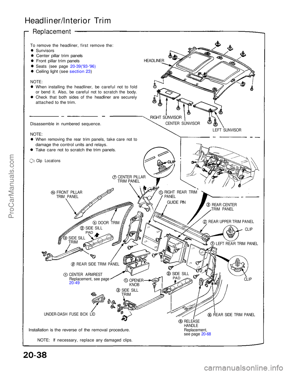
To remove the headliner, first remove the: Sunvisors
Center pillar trim panels
Front pillar trim panels
Seats (see page 20-39('93-'96)
Ceiling light (see section 23)
NOTE:
When installing the headliner, be careful not to fold
or bend it. Also, be careful not to scratch the body.
Check that both sides of the headliner are securely
attached to the trim.
Disassemble in numbered sequence.
NOTE: When removing the rear trim panels, take care not to
damage the control units and relays.
Take care not to scratch the trim panels.
Clip Locations
CENTER PILLAR
TRIM PANEL
FRONT PILLAR
TRIM PANEL
DOOR TRIM
SIDE SILL
PAD
SIDE SILL
TRIM
REAR SIDE TRIM PANEL
CENTER ARMREST
Replacement, see page
20-49
OPENER
KNOB
SIDE SILL
TRIM
UNDER-DASH FUSE BOX LID
Installation is the reverse of the removal procedure.
NOTE: If necessary, replace any damaged clips.
RELEASE
HANDLE
Replacement,
see page 20-68
REAR SIDE TRIM PANEL CLIP
SIDE SILL
PAD
LEFT REAR TRIM PANEL
CLIP
REAR UPPER TRIM PANEL REAR CENTER
TRIM PANEL
GUIDE PIN
RIGHT REAR TRIM
PANEL LEFT SUNVISOR
CENTER SUNVISOR
RIGHT SUNVISOR
HEADLINERProCarManuals.com
Page 615 of 1640
Front Bumpe r
Replacemen t
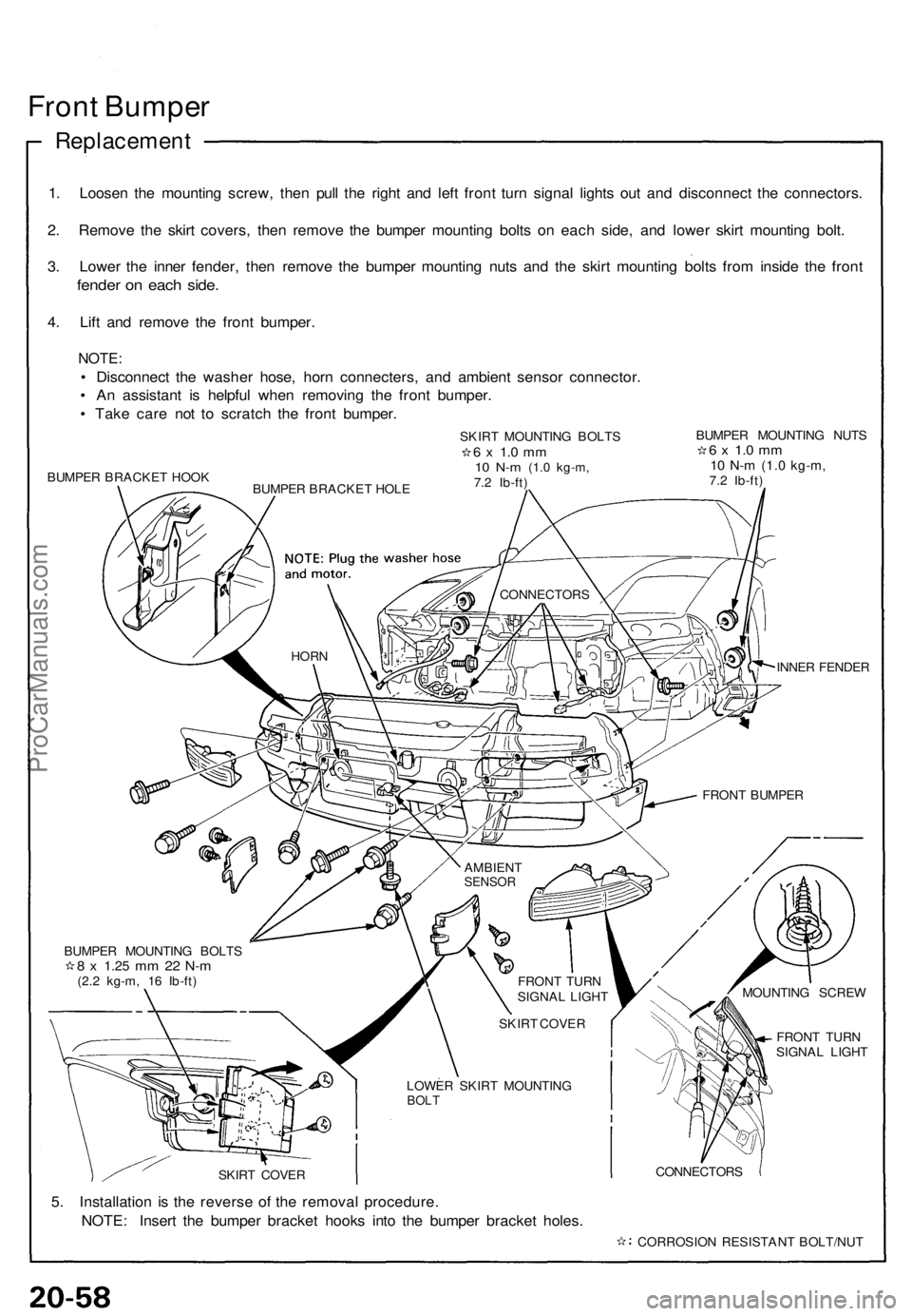
1. Loose n th e mountin g screw , the n pul l th e righ t an d lef t fron t tur n signa l light s ou t an d disconnec t th e connectors .
2 . Remov e th e skir t covers , the n remov e th e bumpe r mountin g bolt s o n eac h side , an d lowe r skir t mountin g bolt .
3 . Lowe r th e inne r fender , the n remov e th e bumpe r mountin g nut s an d th e skir t mountin g bolt s fro m insid e th e fron t
fende r o n eac h side .
4. Lif t an d remov e th e fron t bumper .
NOTE:
• Disconnec t th e washe r hose , hor n connecters , an d ambien t senso r connector .
• A n assistan t i s helpfu l whe n removin g th e fron t bumper .
• Tak e car e no t t o scratc h th e fron t bumper .
BUMPER BRACKE T HOO K
INNER FENDE R
FRON T TUR N
SIGNA L LIGH T
5. Installatio n i s th e revers e o f th e remova l procedure .
NOTE : Inser t th e bumpe r bracke t hook s int o th e bumpe r bracke t holes .
CONNECTOR S
CORROSIO N RESISTAN T BOLT/NU T
BUMPE
R MOUNTIN G BOLT S
8 x 1.2 5 mm 2 2 N- m(2.2 kg-m , 1 6 Ib-ft ) AMBIEN
T
SENSOR
FRONT BUMPE R
HORN
CONNECTOR S
FRONT TUR N
SIGNA L LIGH T
SKIR T COVE R
LOWE R SKIR T MOUNTIN G
BOLT
MOUNTIN G SCRE W
SKIR T COVE R SKIR
T MOUNTIN G BOLT S
6 x 1. 0 m m10 N- m (1. 0 kg-m ,7.2 Ib-ft ) BUMPE
R MOUNTIN G NUT S
6 x 1. 0 m m10 N- m (1. 0 kg-m ,7.2 Ib-ft )
BUMPE R BRACKE T HOL E
ProCarManuals.com
Page 652 of 1640
Roof
Lock Receivers Adjustment
NOTE : Thi s adjustmen t shoul d b e don e i n th e followin g
orde r afte r removin g o r replacin g th e loc k receiver .
1 . Loose n th e loc k receive r mountin g bolt s a t eac h o f
th e fou r corners , the n tighte n the m lightly .
2 . Instal l th e roo f o n th e body .
CAUTION : Whe n installin g th e roof , mak e sur e
bot h roo f sid e lock s ar e unlocked .
NOTE:
• Mak e sur e eac h roo f sid e hoo k align s wit h th e
hoo k sto p properly .
• Befor e securin g th e roo f b y turnin g eac h roo f
sid e loc k handle , chec k tha t th e roo f sid e retaine r
aligns agains t th e fron t pilla r retaine r an d rea r
pillar pane l evenl y a t eac h side , an d chec k tha t
th e seal s fi t flush .
ProCarManuals.com
Page 668 of 1640
Seals/Retainers Alignmen t
Adjustmen t
NOTE: Whe n th e followin g part s hav e bee n replace d o r
removed , thi s adjustmen t shoul d b e done .
• Roo f sid e seal s
• Roo f sid e loc k unit s
• Fron t an d rea r pilla r seal s
CAUTION : T o preven t damage , plac e th e roo f o n a n
appropriat e pad .
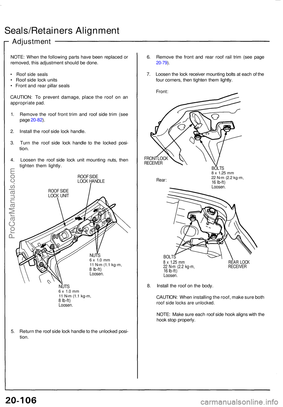
1. Remov e th e roo f fron t tri m an d roo f sid e tri m (se e
pag e 20-82 ).
2 . Instal l th e roo f sid e loc k handle .
3 . Tur n th e roo f sid e loc k handl e t o th e locke d posi -
tion.
4. Loose n th e roo f sid e loc k uni t mountin g nuts , the n
tighte n the m lightly .
ROOF SID E
LOC K HANDL E
ROOF SID ELOC K UNI T
NUT S6 x 1. 0 m m11 N- m (1. 1 kg-m ,8 Ib-ft )
Loosen .
NUTS6 x 1. 0 m m11 N- m (1. 1 kg-m ,8 Ib-ft )
Loosen .
5. Retur n th e roo f sid e loc k handl e to th e unlocke d posi -
tion . 6
. Remov e th e fron t an d rea r roo f rai l tri m (se e pag e
20-79 ).
7 . Loose n th e loc k receive r mountin g bolt s a t eac h o f th e
fou r corners , the n tighte n the m lightly .
Front:
FRON T LOC KRECEIVE R
Rear:
BOLT S8 x 1.2 5 mm22 N- m (2. 2 kg-m ,16 Ib-ft )
Loosen .
BOLTS
8 x 1.2 5 m m REA R LOC K22 N- m (2. 2 kg-m , RECEIVE R16 Ib-ft )
Loosen .
8. Instal l th e roo f o n th e body .
CAUTION : Whe n installin g th e roof , mak e sur e bot h
roof sid e lock s ar e unlocked .
NOTE: Mak e sur e eac h roo f sid e hoo k align s wit h th e
hoo k sto p properly .
ProCarManuals.com
Page 678 of 1640
('93-'96), 86 ('91-'92 Models)
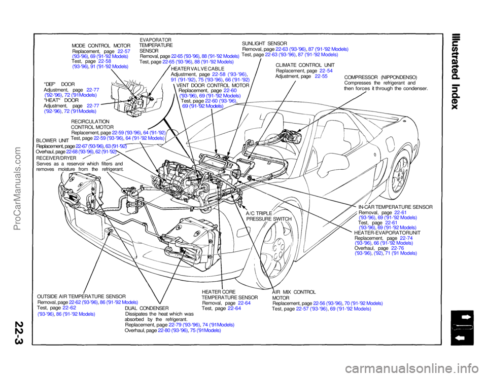
MODE CONTROL MOTOR
Replacement, page 22-57
('93-'96), 69 ('91-'92 Models)
Test, page 22-58
('93-'96), 91 ('91-'92 Models)
"DEF" DOOR
Adjustment, page 22-77
('92-'96), 72 ('91Models)
"HEAT" DOOR
Adjustment, page 22-77
('92-'96), 72 ('91Models)
RECIRCULATION
CONTROL MOTOR
Replacement, page 22-59 ('93-'96), 64 ('91-'92)
Test, page 22-59 ('93-'96), 64 ('91-'92 Models)
BLOWER UNIT
Replacement, page 22-67 ('93-'96), 63 ('91-'92)Overhaul, page 22-68 ('93-'96), 62 ('91-'92)
RECEIVER/DRYER
Serves as a reservoir which filters and
removes moisture from the refrigerant.
OUTSIDE AIR TEMPERATURE SENSOR
Removal, page 22-62 ('93-'96), 86 ('91-'92 Models)
Test, page 22-62
DUAL CONDENSER
Dissipates the heat which was
absorbed by the refrigerant.
Replacement, page 22-79 ('93-'96), 74 ('91Models)Overhaul, page 22-80 ('93-'96), 75 ('91Models)
HEATER CORE
TEMPERATURE SENSOR
Removal, page 22-64
Test, page 22-64
AIR MIX CONTROL
MOTOR
Replacement, page 22-56 ('93-'96), 70 ('91-'92 Models)
Test, page 22-57 ('93-'96), 69 ('91-'92 Models)
HEATER-EVAPORATORUNIT
Replacement, page 22-74('93-'96), 66 ('91-'92 Models)
Overhaul, page 22-76 ('93-'96), ('92), 71 ('91 Models) IN-CAR TEMPERATURE SENSOR
Removal, page 22-61('93-'96), 69 ('91-'92 Models)
Test, page 22-61 ('93-'96), 69 ('91-'92 Models)
COMPRESSOR (NIPPONDENSO)
Compresses the refrigerant and
then forces it through the condenser.
CLIMATE CONTROL UNIT
Replacement, page 22-54
Adjustment, page 22-55
SUNLIGHT SENSOR
Removal, page 22-63 ('93-'96), 87 ('91-'92 Models)Test, page 22-63 ('93-'96), 87 ('91-'92 Models)
EVAPORATOR
TEMPERATURE
SENSOR
Removal, page 22-65 ('93-'96), 88 ('91-'92 Models)
Test, page 22-65 ('93-'96), 88 ('91-'92 Models)
HEATER VALVE CABLE
Adjustment, page 22-58 ('93-'96),
91 ('91-'92), 75 ('93-'96), 66 ('91-'92)
VENT DOOR CONTROL MOTOR
Replacement, page 22-60
('93-'96)
, 69 ('91-'92 Models)
Test, page 22-60 ('93-'96),
69 ('91-'92 Models)
A/C TRIPLE
PRESSURE SWITCHProCarManuals.com
Page 684 of 1640
SRS components are located in this area. Review the SRS component locations, precautions, and procedures in the SRS
section 24 before performing repairs or service.
POWER TRANSISTORBLOWER MOTOR
RECIRCULATION
CONTROL
MOTOR
CONDENSER
FAN MOTOR UNDER-HOOD RELAY BOX A
(CONDENSER FAN RELAY, COMPRESSOR CLUTCH RELAY,
BLOWER MOTOR HIGH RELAY, BLOWER MOTOR RELAY)
UNDER-HOOD
FUSE/RELAY
BOX
HEATER CORE TEMPERATURE SENSOR
CLIMATE CONTROL UNIT VENT DOOR
CONTROL MOTOR
OUTSIDE AIR
TEMPERATURE SENSOR ENGINE COMPARTMENT
FUSE/RELAY BOX
A/C TRIPLE PRESSURE SWITCH
FAN CONTROL UNIT (Fan radiator and con-
denser fans inside car,
behind seats)
EVAPORATOR
TEMPERATURE
SENSOR
IN-CAR
TEMPERATURE
SENSOR
MODE CONTROL
MOTOR
AIR MIX CONTROL MOTOR
SUNLIGHT
SENSORProCarManuals.com
Page 685 of 1640
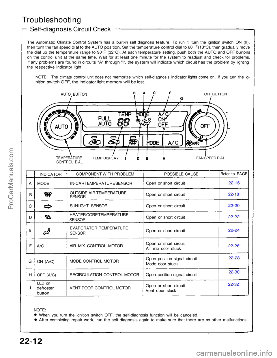
Troubleshooting
Self-diagnosis Circuit Check
The Automatic Climate Control System has a built-in self diagnosis feature. To run it, turn the ignition switch ON (II),
then turn the fan speed dial to the AUTO position. Set the temperature control dial to 60° F(18°C), then gradually move
0
th
e
dial up the temperature range to 90°F (32°C). At each temperatu\
re setting, push both the AUTO and OFF burtons
o
n
the control unit at the same time. Wait for at least one minute for the\
system to readjust and check for problems.
If any problems are found in circuits "A" through "I", the system will indicate which circuit has the problem by lighting
the respective indicator light.
NOTE: The climate control unit does not memorize which self-diagnosis indicator lights come on. If you turn the ig-
nition switch OFF, the indicator light memory will be lost.
AUTO BUTTON
OFF BUTTON
TEMPERATURE CONTROL DIAL
TEMP DISPLAY
FAN SPEED DIAL
NOTE:
When you turn the ignition switch OFF, the self-diagnosis function will be canceled. After completing repair work, run the self-diagnosis again to make sure that there are no other malfunctions.COMPONENT WITH PROBLEM
IN-CAR TEMPERATURE SENSOR
OUTSIDE AIR TEMPERATURE
SENSOR
SUNLIGHT SENSOR
HEATER CORE TEMPERATURE
SENSOR
EVAPORATOR TEMPERATURE
SENSOR
AIR MIX CONTROL MOTOR
MODE CONTROL MOTOR
RECIRCULATION CONTROL MOTOR
VENT DOOR CONTROL MOTOR
POSSIBLE CAUSE
Open or short circuit
Open or short circuit
Open or short circuit
Open or short circuit
Open or short circuit
Open or short circuit
Air mix door stuck
Open position signal circuit
Mode door stuck
Open position signal circuit
Open or short circuit
Vent door stuck
Refer to PAGE
22-16
22-1
8
22-20
22-22
22-24
22-2
6
22-28
22-30
22-32
INDICATOR
MODE
A/C
ON
(A/C)
OFF
(A/C)
LED on
defroster
button
A
B
C
D
E
F
G
H
I
ProCarManuals.com
Page 699 of 1640
Sunlight Sensor
Removal
With a small screwdriver, carefully pry the sunlight sen-
sor out of the dashboard and disconnect its connector.
Protect the dashboard; cover it with a shop towel before
you pry against it.
SUNLIGHT
SENSOR
Test
Measure the voltage between the terminals with the sen-
sor out of direct sunlight.
• With the connector connected (probe the back of it):
1.4 ± 0.2 V
• With the connector disconnected: 0.1 — 0.2 VProCarManuals.com