Page 836 of 1640
Lighting System
Retractor Motor Replacement
CAUTION:
• Halogen headlights can become very hot in use; do
not touch them or the attaching hardware immediately
after they have been turned off.
• Do not try to replace or clean headlights with the lights
on.
1. Remove the No. 42 (15 A) and No. 43 (15 A) fuses
from the under-hood fuse/relay box.
No. 43
(15A)
FUSE
No. 42
(15A)
FUSE
UNDER-HOOD FUSE/RELAY BOX
2. Turn the knob clockwise to raise the headlight.
CAP
KNOB
3. Remove the two caps, four screws, and cowl clips.
COWL CLIP
CAP
SCREW
4. Slide the headlight housing forward and up.
NOTE: Be careful not to damage the front bumper
or the headlight housing.
HEADLIGHT HOUSING
PROTECTIVE TAPE
5. Disconnect the 6-P connector from the headlight
unit.
6-P CONNECTOR
HEADLIGHT UNIT
6. Remove the four mounting bolts, then remove the
unit.
MOUNTING
BOLTSProCarManuals.com
Page 838 of 1640
Headlight Housing Adjustment
1. Remove the stop bolt caps.
2. Adjust stop bolts A and B.
STOP BOLT CAPS
STOP
BOLT A
STOP
BOLT B
STOP
BOLTC
STOP BOLT
LOCKNUT
3. Adjust stop bolt C in or out until the headlight hous-
ing fits flush with the front fender when the head-
light is down.
STOP BOLT C
HEADLIGHT HOUSING
(cont'd)ProCarManuals.com
Page 839 of 1640
Lighting System
Headlight Housing Adjustment
(cont'd)
4. Adjust the retractor motor toward
front
or rear until
the headlight housing fits flush with the front fender
when the headlight is down.
NOTE: Be careful not to damage the headlight
housing.
HEADLIGHT
HOUSING
RETRACTOR
MOTORProCarManuals.com
Page 840 of 1640
Lighting Syste m
Retracto r Moto r Tes t
1. Remov e th e retracto r motor .
2 . Tes t th e moto r b y connectin g batter y powe r t o th e
A termina l an d groun d t o th e D terminal .
Th e moto r shoul d ru n continuously .
3 . I f th e moto r doe s no t ru n o r fail s t o ru n smoothly ,
replace it .
NOTE : Th e illustratio n show s th e moto r i n th e con -
ditio n whe n th e headligh t i s full y raised .
RETRACTO RKNOB
View fro mtermina l sid e
BCTermina l
Position
At close d positio n
At ope n positio n
4. Disconnec t th e powe r supply , and chec k fo r con -
tinuit y betwee n th e terminal s accordin g t o th e ta -
bl e whil e turnin g th e retracto r kno b clockwise .
ProCarManuals.com
Page 841 of 1640
Headlight Relay Test
1. Remove the headlight relay from the under-hood
fuse/relay box.
2. Check continuity at the relay terminals.
• There should be continuity between the C and D
terminals.
• There should be continuity between the A and B
terminals when power and ground are connect-
ed to the C and D terminals.
• There should be no continuity between the A and
B terminals when power is disconnected.
Dimmer Relay Test
1. Remove the dimmer relay from the under-hood
fuse/relay box.
2. Check continuity at the relay terminals.
• There should be continuity between the F and E
terminals and between the B and C terminals.
• There should be continuity between the A and C
terminals when power and ground are connect-
ed to the E and F terminals.
• There should be no continuity between the A and
C terminals when power is disconnected.ProCarManuals.com
Page 842 of 1640

Lighting Syste m
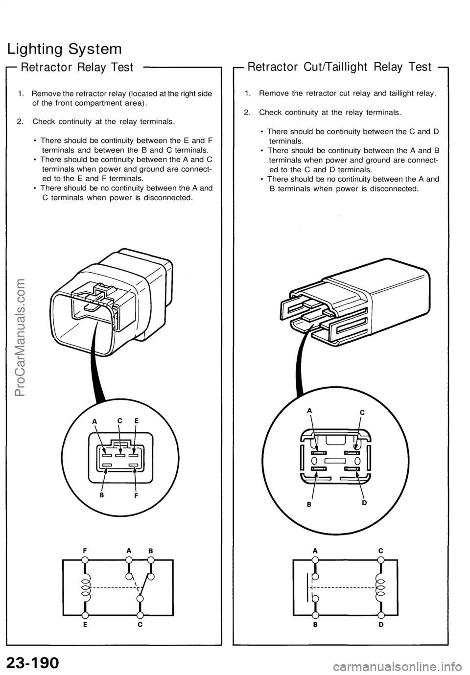
Retracto r Rela y Tes t
1. Remov e th e retracto r rela y (locate d a t th e righ t sid e
o f th e fron t compartmen t area) .
2 . Chec k continuit y a t th e rela y terminals .
• Ther e shoul d b e continuit y betwee n th e E an d F
terminal s an d betwee n th e B an d C terminals .
• Ther e shoul d b e continuit y betwee n th e A an d C
terminal s whe n powe r an d groun d ar e connect -
e d t o th e E an d F terminals .
• Ther e shoul d b e n o continuit y betwee n th e A an d
C terminal s whe n powe r i s disconnected .
Retractor Cut/Tailligh t Rela y Tes t
1. Remov e th e retracto r cu t rela y an d tailligh t relay .
2 . Chec k continuit y a t th e rela y terminals .
• Ther e shoul d b e continuit y betwee n th e C an d D
terminals .
• Ther e shoul d b e continuit y betwee n th e A an d B
terminal s whe n powe r an d groun d ar e connect -
e d t o th e C an d D terminals .
• Ther e shoul d b e n o continuit y betwee n th e A an d
B terminal s whe n powe r i s disconnected .
ProCarManuals.com
Page 843 of 1640
Headlights
Description
The light first forms basic pattern A after being interrupt-
ed by the interrupter plate and passed through the con-
vex lens. The interrupter plate determines the form.
The outer lens distributes the light into pattern B.
Screen
CONVEX LENS
INTERRUPTER PLATE
BULB
REFLECTOR
OUTER LENSProCarManuals.com
Page 844 of 1640
Headlights
Adjustment
Adjust the headlights to local requirements by turning the adjusters as shown.
NOTE: Be careful not to damage the front fender or the
headlight housing when adjusting.
HEADLIGHT HORIZONTAL
AIM ADJUSTER
HEADLIGHT VERTICAL
AIM ADJUSTER
PROTECTIVE TAPEProCarManuals.com