Page 706 of 1640

A/C Syste m Servic e
Performanc e Tes t
The performanc e tes t wil l hel p determin e i f th e ai r con -
ditionin g syste m is operatin g withi n specifications .
Only us e servic e equipmen t tha t i s U.L.-liste d an d is cer -
tifie d t o mee t th e requirement s o f SA E J221 0 t o remov e
HFC-134 a (R-134a ) fro m th e ai r conditionin g system .
CAUTION : Exposur e t o ai r conditione r refrigeran t
an d lubrican t vapo r o r mis t ca n irritat e eyes , nos e
an d throat . Avoi d breathin g th e ai r conditione r
refrigeran t an d lubrican t vapo r o r mist .
I f accidenta l syste m discharg e occurs , ventilat e wor k
are a befor e resumin g service .
R-134 a servic e equipmen t o r vehicl e ai r conditionin g sys -
te m shoul d no t b e pressur e teste d o r lea k teste d wit h
compresse d air .
Som e mixture s o f ai r an d R-134 a hav e
bee n show n to b e combustibl e a t elevate d pressure s
an d ca n resul t i n fir e o r explosio n causin g injur y o r
propert y damage . Neve r us e compresse d ai r t o pres -
sure tes t R-134 a servic e equipmen t o r vehicl e ai r
conditionin g systems .
Additiona l healt h an d safet y informatio n ma y b e obtaine d
fro m th e refrigeran t an d lubrican t manufacturers .
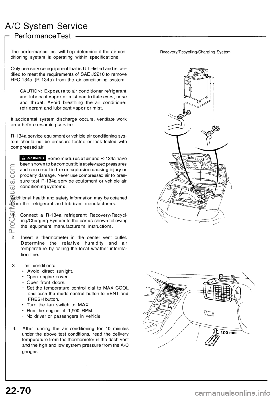
1 . Connec t a R-134 a refrigeran t Recovery/Recycl -
ing/Chargin g Syste m to th e ca r a s show n followin g
th e equipmen t manufacturer' s instructions .
2 . Inser t a thermomete r i n th e cente r ven t outlet .
Determin e th e relativ e humidit y an d ai r
temperatur e b y callin g th e loca l weathe r informa -
tion line .
3. Tes t conditions :
• Avoi d direc t sunlight .
• Ope n engin e cover .
• Ope n fron t doors .
• Se t th e temperatur e contro l dia l t o MA X COO L
an d pus h th e mod e contro l butto n t o VEN T an d
FRES H button .
• Tur n th e fa n switc h t o MAX .
• Ru n th e engin e a t 1,50 0 RPM .
• N o drive r o r passenger s i n vehicle .
4 . Afte r runnin g th e ai r conditionin g fo r 1 0 minute s
unde r th e abov e tes t conditions , rea d th e deliver y
temperatur e fro m th e thermomete r i n th e das h ven t
an d th e hig h an d low syste m pressur e fro m th e A/ C
gauges .
Recovery/Recycling/Chargin g Syste m
ProCarManuals.com
Page 732 of 1640
Relay and Control Unit Locations
Front Compartment
HORN RELAY
A/C COMPRESSOR CLUTCH
RELAY
RADIATOR FAN
LOW RELAY
RADIATOR FAN
HIGH RELAY
CONDENSER FAN RELAY
UNDER-HOOD RELAY BOX A
LEFT HEADLIGHT RETRACTOR
CUT RELAY
WINDSHIELD WIPER
LOW RELAY
WINDSHIELD WIPER
INTERMITTENT RELAY
POWER AMPLIFIER
RELAY
ABS
REAR FAIL-SAFE RELAY
ABS FRONT
FAIL-SAFE RELAY
HEADLIGHT RELAY
RIGHT HEADLIGHT RETRACTOR RELAY
Wire colors: BLU/GRN,
BRN/WHT, BLU/RED,
GRN/YEL, and BLK
LEFT HEADLIGHT RETRACTOR RELAY
Wire colors: BLU/BLK,
WHT/BLK, GRN/RED,
BLU,
and BLK
RIGHT HEADLIGHT RETRACTOR
CUT RELAY
BLOWER RELAY
BLOWER HIGH RELAY
WINDSHIELD WIPER
HIGH RELAY
WINDSHIELD
WASHER RELAY
UNDER-HOOD
RELAY BOX B
DIMMER RELAY
POWER WINDOW
RELAY
TAILLIGHT RELAY
ABS MOTOR RELAY
UNDER-HOOD FUSE/RELAY BOXProCarManuals.com
Page 733 of 1640
Relay and Control Unit Locations
Dashboard
TURN SIGNAL/HAZARD
RELAY
CLIMATE CONTROL UNIT
UNDER-DASH FUSE BOX
FOOT WELL LIGHT
DASHBOARD
LOWER COVER
INTEGRATED
CONTROL UNIT
SRS UNITProCarManuals.com
Page 734 of 1640
Dashboard, Door and Floor
DRIVER'S DOOR PANEL
ABS CONTROL UNIT
DAYTIME RUNNING
LIGHTS CONTROL
UNIT (Canada)
POWER WINDOW
CONTROL UNIT
STARTER CUT RELAY
Wire colors: BLK/WHT,
BLK/WHT, BLK/GRN,
and BLK/BLU
SECURITY CONTROL UNIT
CIGARETTE LIGHTER
RELAY
Wire colors: YEL/RED,
BLU/GRN, BRN/YEL, and BLK
FOOT WELL BASS SPEAKER
EPS CONTROL UNIT
(Behind foot well
bass speaker)
RIGHT FRONT FLOOR
PANEL
SRS UNIT
POWER DOOR LOCK
CONTROL UNITProCarManuals.com
Page 735 of 1640
Relay and Control Unit Locations
Rear Bulkhead
PGM-FI MAIN RELAY
THROTTLE VALVE CONTROL
MOTOR RELAY
Wire colors: BLK,
YEL/BLK, GRN/RED,
and WHT/BLU
TCS CONTROL UNIT
TRANSMISSION CONTROL
MODULE (TCM) (A/T)
PULSE UNIT (M/T)
DASH LIGHTS
BRIGHTNESS
CONTROL UNIT
FAN CONTROL
UNIT
ECMProCarManuals.com
Page 789 of 1640
Gauge Assembly
Bulb Locations
GAUGE LIGHTS (1.4W x 2)
SRS INDICATOR LIGHT (1.4 W)
RIGHT TURN SIGNAL INDICATOR LIGHT (1.4 W)
EPS INDICATOR LIGHT (1.4 W)
BRAKE SYSTEM LIGHT (1.4 W)
SEAT BELT REMINDER LIGHT (1.4 W)
TCS INDICATOR
LIGHT (1.96 W)
LOW FUEL INDICATOR
LIGHT (1.4 W)
GAUGE LIGHT
(1.4
W)
HIGH BEAM INDICATOR LIGHT (1.4 W)
LEFT TURN SIGNAL INDICATOR LIGHT (1.4 W)
ABS
INDICATOR LIGHT (1.4 W)
CHARGING SYSTEM LIGHT (1.4 W)
MALFUNCTION
INDICATOR
LAMP (MIL)
(1.4W)
LOW OIL PRESSURE
INDICATOR
LIGHT (1.4 W)
GAUGE LIGHT
(1.4
W)
GAUGE LIGHT
(3.0
W)
GAUGE LIGHT
(3.0
W)
GAUGE LIGHT
(3.0
W)
CRUISE INDICATOR LIGHT
(1.96
W)ProCarManuals.com
Page 790 of 1640

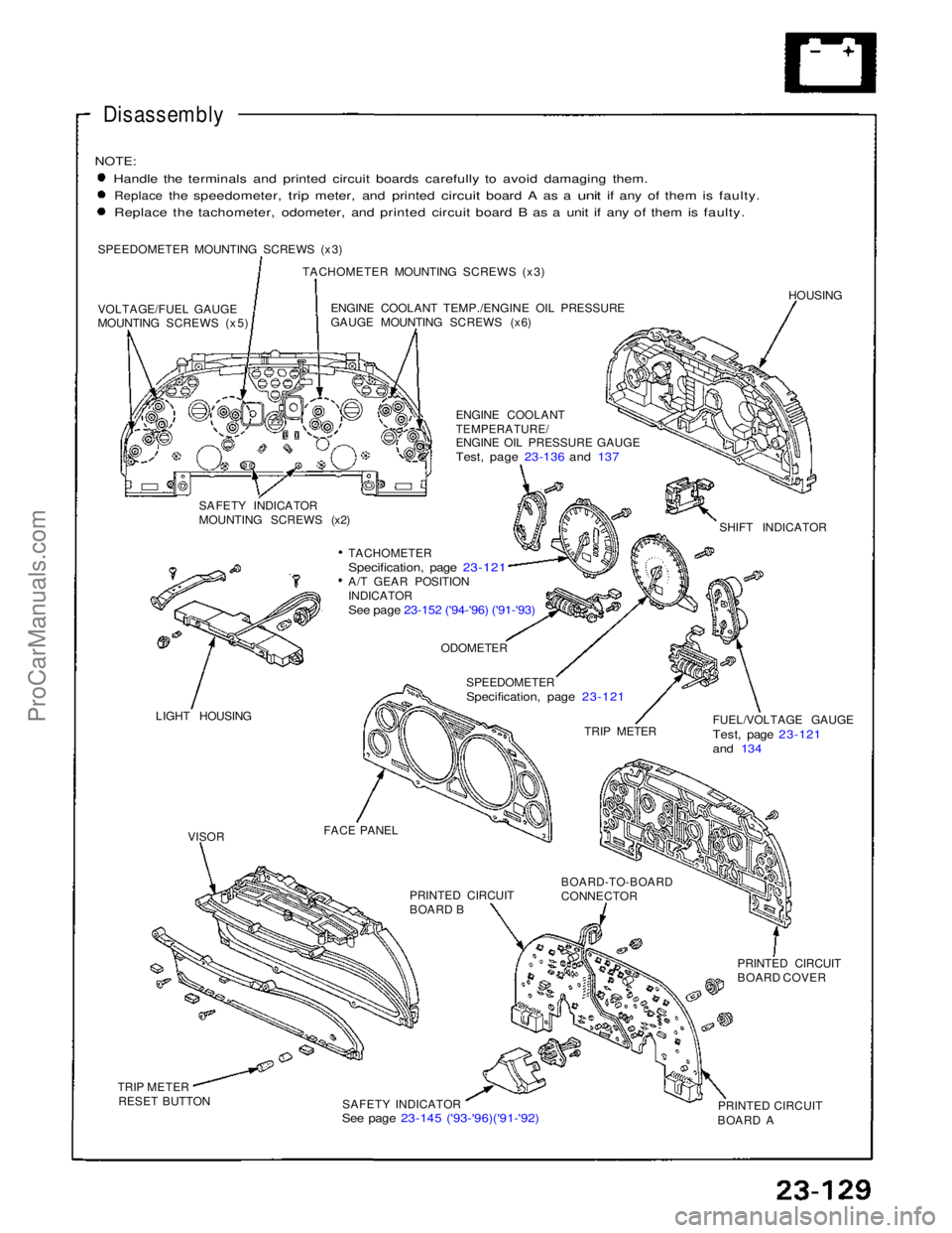
Disassembly
NOTE:
Handle the terminals and printed circuit boards carefully to avoid damaging them.
Replace
the
speedometer,
trip
meter,
and
printed
circuit
board
A as a
unit
if any of
them
is
faulty. Replace the tachometer, odometer, and printed circuit board B as a unit if any of them is faulty.
SPEEDOMETER MOUNTING SCREWS (x3) TACHOMETER MOUNTING SCREWS (x3)
VOLTAGE/FUEL GAUGE
MOUNTING SCREWS (x5) ENGINE COOLANT TEMP./ENGINE OIL PRESSURE
GAUGE MOUNTING SCREWS (x6)
HOUSING
ENGINE COOLANT
TEMPERATURE/
ENGINE OIL PRESSURE GAUGE
Test, page 23-136 and 137
SAFETY INDICATOR
MOUNTING SCREWS (x2) SHIFT INDICATOR
TACHOMETER
Specification, page 23-121
A/T GEAR POSITION
INDICATOR
See page 23-152 ('94-'96) ('91-'93)
LIGHT HOUSING
ODOMETER
SPEEDOMETER
Specification, page 23-121
TRIP METER FUEL/VOLTAGE GAUGE
Test, page 23-121
and 134
FACE PANEL PRINTED CIRCUIT
BOARD B
BOARD-TO-BOARD
CONNECTOR
PRINTED CIRCUIT
BOARD COVER
PRINTED CIRCUIT
BOARD A
SAFETY INDICATOR
See page 23-145 ('93-'96)('91-'92)
TRIP METER
RESET BUTTON
VISORProCarManuals.com
Page 799 of 1640

Brake Warnin g Syste m
Parking Brak e Switc h Tes t
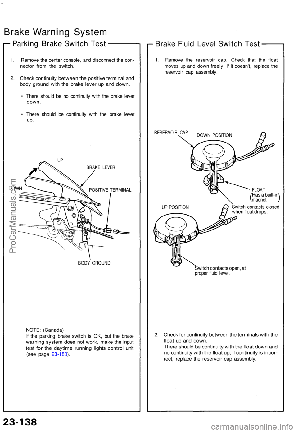
1. Remov e th e cente r console , an d disconnec t th e con -
necto r fro m th e switch .
2. Chec k continuit y betwee n th e positiv e termina l an d
bod y groun d wit h th e brak e leve r u p an d down .
• Ther e shoul d b e n o continuit y wit h th e brak e leve r
down .
• Ther e shoul d b e continuit y wit h th e brak e leve r
up.
DOW N
BRAK E LEVE R
POSITIV E TERMINA L
BODY GROUN D
NOTE: (Canada )
I f th e parkin g brak e switc h i s OK , bu t th e brak e
warnin g syste m doe s no t work , mak e th e inpu t
test fo r th e daytim e runnin g light s contro l uni t
(see pag e 23-180 ).
Brak e Flui d Leve l Switc h Tes t
1. Remov e th e reservoi r cap . Chec k tha t th e floa t
move s u p an d dow n freely ; i f i t doesn't , replac e th e
reservoi r ca p assembly .
RESERVOI R CA P
FLOAT
Has a built-i nmagne t
Switch contact s close dwhen floa t drops .
Switc h contact s open , a t
prope r flui d level .
2. Chec k fo r continuit y betwee n th e terminal s wit h th e
floa t u p an d down .
There shoul d b e continuit y wit h th e floa t dow n an d
no continuit y wit h th e floa t up ; i f continuit y is incor -
rect, replac e th e reservoi r ca p assembly .
UP POSITIO N
DOWN POSITIO N
UP
ProCarManuals.com