1991 ACURA NSX flat tire
[x] Cancel search: flat tirePage 11 of 1640
Towing
If th e ca r need s t o b e towed , cal l a professiona l towin g
service . Neve r to w th e ca r behin d anothe r ca r wit h jus t
a rop e o r chain . I t i s ver y dangerous .
Ther e ar e thre e widel y use d method s o f towin g a car :
Flat-be d Equipmen t — Th e operato r load s th e ca r o n th e
bac k o f a truck . Thi s i s th e onl y recommende d wa y o f
towin g th e NS X & NSX-T .
Whee l Lif t Equipment— The to w truc k drive r use s tw o
pivotin g arm s whic h g o unde r th e tire s (fron t o r rear ) an d
lif t the m of f th e ground . Th e othe r tw o wheel s remai n
o n th e ground . Thi s towin g metho d i s no t recommend -
ed . Becaus e o f th e NS X & NSX-T' s lo w groun d clearance ,
th e bod y ca n b e damage d goin g ove r larg e bump s o r u p
inclines .
Sling-typ e Equipment— The tow truc k use s meta l chain s
wit h hook s o n th e ends . Thes e hook s g o aroun d part s
of th e fram e or suspensio n and th e cable s lift tha t end
of th e ca r of f th e ground . Damag e t o th e car' s suspen -
sio n an d bod y i s almos t certai n if thi s metho d o f towin g
i s attempted .
I f th e NS X & NSX- T canno t b e towe d b y flat-bed , i t
shoul d b e towe d wit h th e rea r wheel s of f th e ground .
If , du e t o damage , th e ca r mus t b e towe d wit h th e rea r
wheel s o n th e ground , d o th e following :
Manual Transmissio n
• Releas e th e parkin g brak e
• Shif t th e transmissio n t o Neutra l
Automati c Transmissio n
• Releas e th e parkin g brak e
• Star t th e engin e
• Shif t t o position , the n t o positio n
• Tur n of f th e engin e
NOTICE :
• Imprope r towin g preparatio n wil l damag e th e trans -
mission . Follo w th e abov e procedur e exactly . Th e ca r
mus t b e towe d o n a fla t be d if th e engin e wil l no t star t
o r th e transmissio n wil l no t shift .
• I t i s bes t t o to w th e ca r n o farthe r tha n 5 0 mile s (8 0
km) , an d kee p th e spee d belo w 3 5 mp h (5 5 km/h) .
• Tryin g t o lif t o r to w th e ca r b y th e bumper s wil l caus e
seriou s damage . Th e bumper s ar e no t designe d to sup -
por t th e car' s weight .
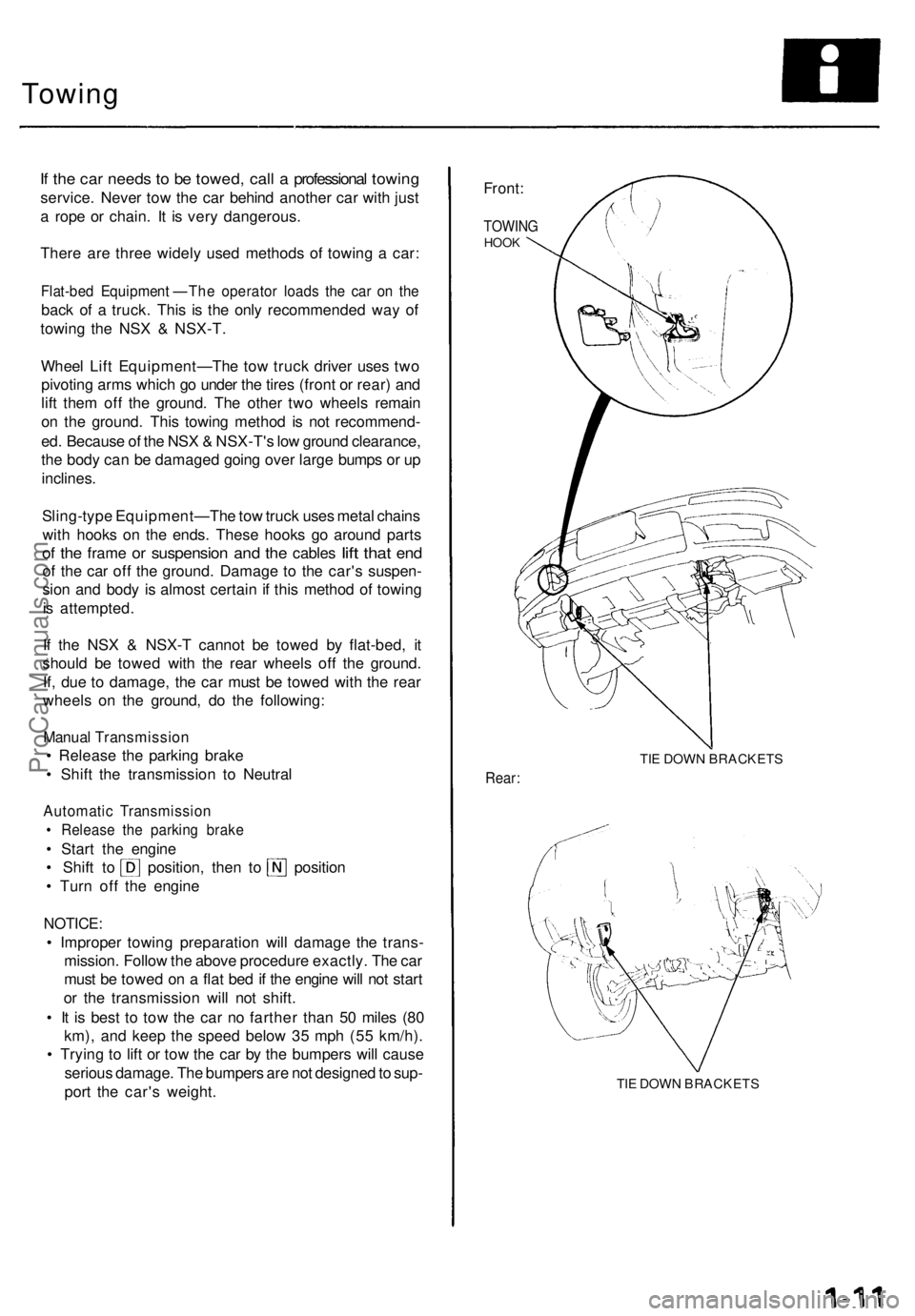
Front:
TOWIN GHOOK
TIE DOW N BRACKET S
Rear:
TIE DOW N BRACKET S
ProCarManuals.com
Page 44 of 1640
Towing
If th e ca r need s t o b e towed , cal l a professiona l towin g
service . Neve r to w th e ca r behin d anothe r ca r wit h jus t
a rop e o r chain . I t i s ver y dangerous .
Ther e ar e thre e widel y use d method s o f towin g a car :
Flat-be d Equipment—Th e operato r load s th e ca r o n th e
bac k o f a truck . This is th e onl y recommende d wa y o f
towin g th e NS X & NSX-T .
Whee l Lif t Equipment—Th e to w truc k drive r use s tw o
pivotin g arm s whic h g o unde r th e tire s (fron t o r rear ) an d
lif t the m of f th e ground . Th e othe r tw o wheel s remai n
o n th e ground . Thi s towin g metho d i s no t recommend -
ed . Becaus e o f th e NS X & NSX-T' s lo w groun d clearance ,
th e bod y ca n b e damage d goin g ove r larg e bump s o r u p
inclines .
Sling-typ e Equipment—Th e to w truc k use s meta l chain s
wit h hooks on th e ends . Thes e hook s g o aroun d part s
o f th e fram e o r suspensio n an d th e cable s lif t tha t en d
o f th e ca r of f th e ground . Damag e t o th e car' s suspen -
sio n an d bod y i s almos t certai n if thi s metho d o f towin g
i s attempted .
I f th e NS X & NSX- T canno t b e towe d b y flat-bed , i t
shoul d b e towe d wit h th e rea r wheel s of f th e ground .
If , du e t o damage , th e ca r mus t b e towe d wit h th e rea r
wheel s o n th e ground , d o th e following :
Manual Transmissio n
Release th e parkin g brak e
Shift th e transmissio n t o Neutra l
Automati c Transmissio n
Releas e th e parkin g brak e
Star t th e engin e
Shift t o position , the n t o positio n
Tur n of f th e engin e
NOTICE :
Improper towin g preparatio n wil l damag e th e trans -
mission . Follo w th e abov e procedur e exactly . Th e ca r
mus t b e towe d o n a fla t be d if th e engin e wil l no t star t
or th e transmissio n wil l no t shift .
It i s bes t t o to w th e ca r n o farthe r tha n 5 0 mile s (8 0
km) , an d kee p th e spee d belo w 3 5 mp h (5 5 km/h) .
Tryin g t o lif t o r to w th e ca r b y th e bumper s wil l caus e
seriou s damage . Th e bumper s ar e no t designe d to sup -
por t th e car' s weight .
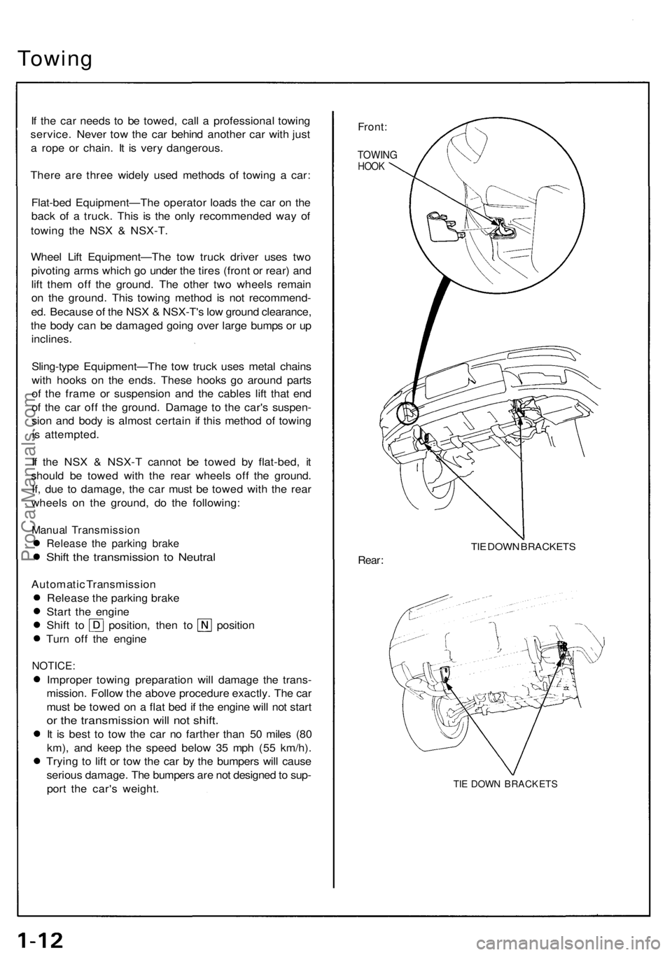
Front:
TOWIN GHOOK
TIE DOW N BRACKET S
Rear:
TIE DOW N BRACKET S
ProCarManuals.com
Page 451 of 1640
Wheel Alignment
Height
NSX/NSX-T four wheel alignment requires the use of equipment designed specifically for four wheel independent
suspensions and capable of immediate feedback.
NOTE: For proper inspection/adjustment of the wheel alignment, check and adjust the following before checking
the alignment.
• Check that the suspension is not modified.
• Check the tire size and tire pressure.
• Check the runout of the wheels and tires.
• Check the suspension ball joints. (Hold a wheel with your hands, then move the wheel up and down and right
and left to check for wobbling.)
• Check the height of each suspension (see below).
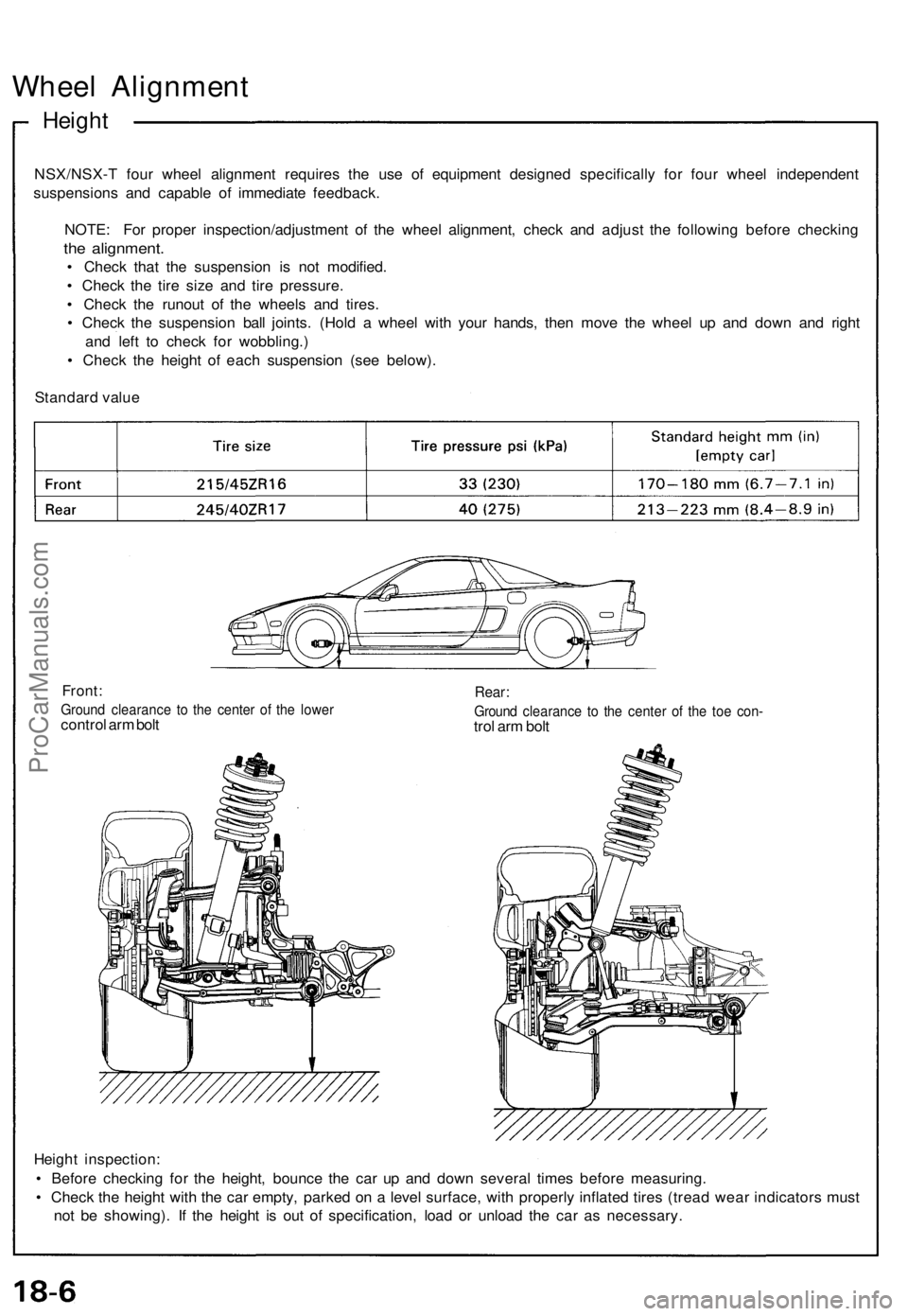
Standard value
Front:
Ground clearance to the center of the lower
control arm bolt
Rear:
Ground clearance to the center of the toe con-
trol arm bolt
Height inspection:
• Before checking for the height, bounce the car up and down several times before measuring.
• Check the height with the car empty, parked on a level surface, with properly inflated tires (tread wear indicators must
not be showing). If the height is out of specification, load or unload the car as necessary.ProCarManuals.com
Page 963 of 1640
Warning/Caution Label Locations
(cont'd)
J: PASSENGER'S INFLATOR CAUTION
DANGER
EXPLOSIVE/FLAMMABLE
CONTACT WITH ACID, WATER OR HEAVY MET-
ALS SUCH AS COPPER, LEAD OF MERCURY
HARMFUL AND IRRITATING GASES OR EXPLO-
SIVE COMPOUNDS.
STORAGE TEMPERATURES MUST NOT EXCEED
200°F
(93°C).
FOR
PROPER
HANDLING STOR-
AGE AND DISPOSAL PROCEDURES REFER TO
THE SERVICE MANUAL, SRS SUPPLEMENT.
POISON
CONTAINS POISONOUS SODIUM AZIDE AND
POTASSIUM NITRATE.
FIRST AID
IF CONTENTS ARE SWALLOWED, INDUCE
VOMITING FOR EYE CONTACT FLUSH EYES
WITH WATER FOR 15 MINUTES.
IF GASES (FROM ACID OR WATER CONTACT)
ARE INHALED, SEEK FRESH AIR.
IN EVERY CASE, GET PROMPT MEDICAL AT-
TENTION.
KEEP OUT OF REACH OF CHILDREN.
WARNING
TO PREVENT ACCIDENTAL DEPLOYMENT AND
POSSIBLE INJURY:
ALWAYS INSTALL THE PROTECTIVE SHORT
CONNECTOR WHEN THE HARNESS IS DIS-
CONNECTED.
UNDER NO CIRCUMSTANCES SHOULD DIAG-
NOSIS BE PERFORMED USING ELECTRICAL
TEST EQUIPMENT OR PROBING DEVICES.
NO SERVICEABLE PARTS INSIDE.
DO NOT DISASSEMBLE OR TAMPER.
STORE THE REMOVED AIRBAG ASSEMBLY
WITH THE PAD SURFACE UP.
FOR SPECIAL HANDLING OR STORAGE REFER
TO THE SERVICE MANUAL.
DISPOSE OF THE ENTIRE UNIT AS DIRECTED.
K: POWRE SOURCE CAUTION
DANGER
DO NOT REMOVE, IMPACT OR DISASSEMBLE.
L: PRETENSIONER ELR CAUTION
CAUTION
FOLLOW THE INSTRUCTIONS BELOW FOR
REMOVAL OF THE PRETENSIONER.
SHORT COUPLER (RED) IS TO BE INSTALLED
IMMEDIATELY WHENEVER COUPLER IS DIS-
ASSEMBLED.
ELECTRIC TESTER SPECIFIED BE USED FOR
CIRCUIT DIAGNOSIS.
THE ANCHOR BOLT IN THE SHOULDER AREA
IS TO BE REMOVED BEFORE THE PRETEN-
SIONER.
NO DISASSEMBLY OR IMPACT ALLOWED.
FOR HANDLING, STORAGE, AND DISPOSAL
METHOD, REFER TO THE SERVICE MANUAL.
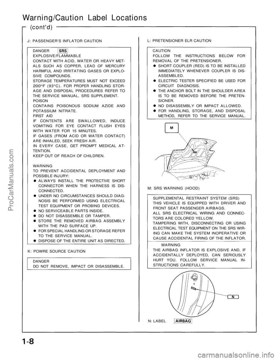
M: SRS WARNING (HOOD)
SUPPLEMENTAL RESTRAINT SYSTEM (SRS)
THIS VEHICLE IS EQUIPPED WITH DRIVER AND
FRONT SEAT PASSENGER AIRBAGS.
ALL SRS ELECTRICAL WIRING AND CONNEC-
TORS ARE COLORED YELLOW.
TAMPERING WITH, DISCONNECTING OR USING
ELECTRICAL TEST EQUIPMENT ON THE SRS WIR-
ING CAN MAKE THE SYSTEM INOPERATIVE OR
CAUSE ACCIDENTAL FIRING OF THE INFLATOR.
WARNING
THE AIRBAG INFLATOR IS EXPLOSIVE AND, IF
ACCIDENTALLY DEPLOYED, CAN SERIOUSLY
HURT YOU. FOLLOW SERVICE MANUAL IN-
STRUCTIONS CAREFULLY.
N: LABELProCarManuals.com
Page 970 of 1640
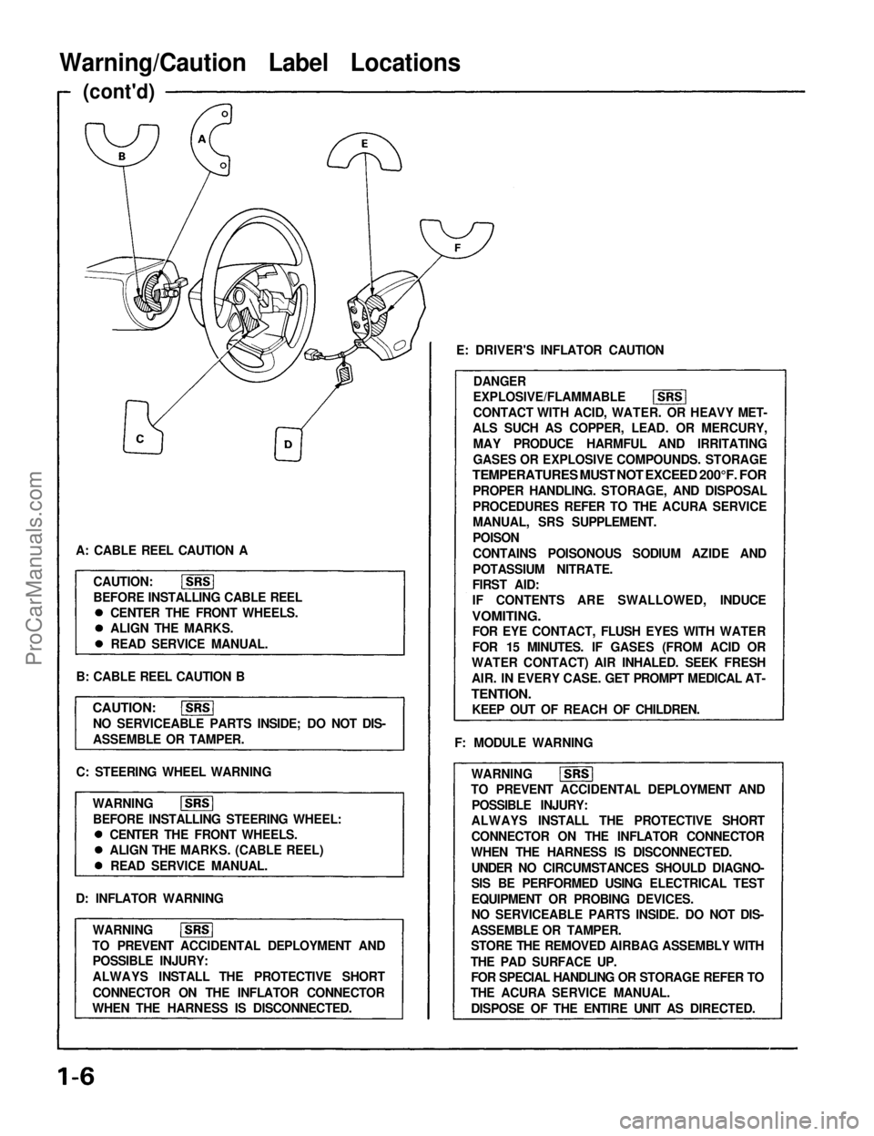
Warning/Caution Label Locations
(cont'd)
A: CABLE REEL CAUTION A CAUTION:
BEFORE INSTALLING CABLE REEL
B: CABLE REEL CAUTION B
CAUTION:
NO SERVICEABLE PARTS INSIDE; DO NOT DIS-
ASSEMBLE OR TAMPER.
C: STEERING WHEEL WARNING WARNINGBEFORE INSTALLING STEERING WHEEL:
D: INFLATOR WARNING WARNING
TO PREVENT ACCIDENTAL DEPLOYMENT AND POSSIBLE INJURY:
ALWAYS INSTALL THE PROTECTIVE SHORT
CONNECTOR ON THE INFLATOR CONNECTOR
WHEN THE HARNESS IS DISCONNECTED. E: DRIVER'S INFLATOR CAUTION
DANGER
EXPLOSIVE/FLAMMABLE
CONTACT WITH ACID, WATER. OR HEAVY MET-
ALS SUCH AS COPPER, LEAD. OR MERCURY,
MAY PRODUCE HARMFUL AND IRRITATING
GASES OR EXPLOSIVE COMPOUNDS. STORAGE
TEMPERATURES MUST NOT EXCEED 200°F. FOR
PROPER HANDLING. STORAGE, AND DISPOSAL
PROCEDURES REFER TO THE ACURA SERVICE
MANUAL, SRS SUPPLEMENT.
POISON
CONTAINS POISONOUS SODIUM AZIDE AND
POTASSIUM NITRATE.
FIRST AID:
IF CONTENTS ARE SWALLOWED, INDUCE
VOMITING.
FOR EYE CONTACT, FLUSH EYES WITH WATER
FOR 15 MINUTES. IF GASES (FROM ACID OR
WATER CONTACT) AIR INHALED. SEEK FRESH
AIR. IN EVERY CASE. GET PROMPT MEDICAL AT-
TENTION.
KEEP OUT OF REACH OF CHILDREN.
F: MODULE WARNING WARNING
TO PREVENT ACCIDENTAL DEPLOYMENT AND
POSSIBLE INJURY:
ALWAYS INSTALL THE PROTECTIVE SHORT
CONNECTOR ON THE INFLATOR CONNECTOR
WHEN THE HARNESS IS DISCONNECTED. UNDER NO CIRCUMSTANCES SHOULD DIAGNO-
SIS BE PERFORMED USING ELECTRICAL TEST
EQUIPMENT OR PROBING DEVICES.
NO SERVICEABLE PARTS INSIDE. DO NOT DIS-
ASSEMBLE OR TAMPER.
STORE THE REMOVED AIRBAG ASSEMBLY WITH
THE PAD SURFACE UP. FOR SPECIAL HANDLING OR STORAGE REFER TO
THE ACURA SERVICE MANUAL.
DISPOSE OF THE ENTIRE UNIT AS DIRECTED.
CENTER THE FRONT WHEELS.
ALIGN THE MARKS.
READ SERVICE MANUAL.
CENTER THE FRONT WHEELS.
ALIGN THE MARKS. (CABLE REEL) READ SERVICE MANUAL.ProCarManuals.com
Page 972 of 1640
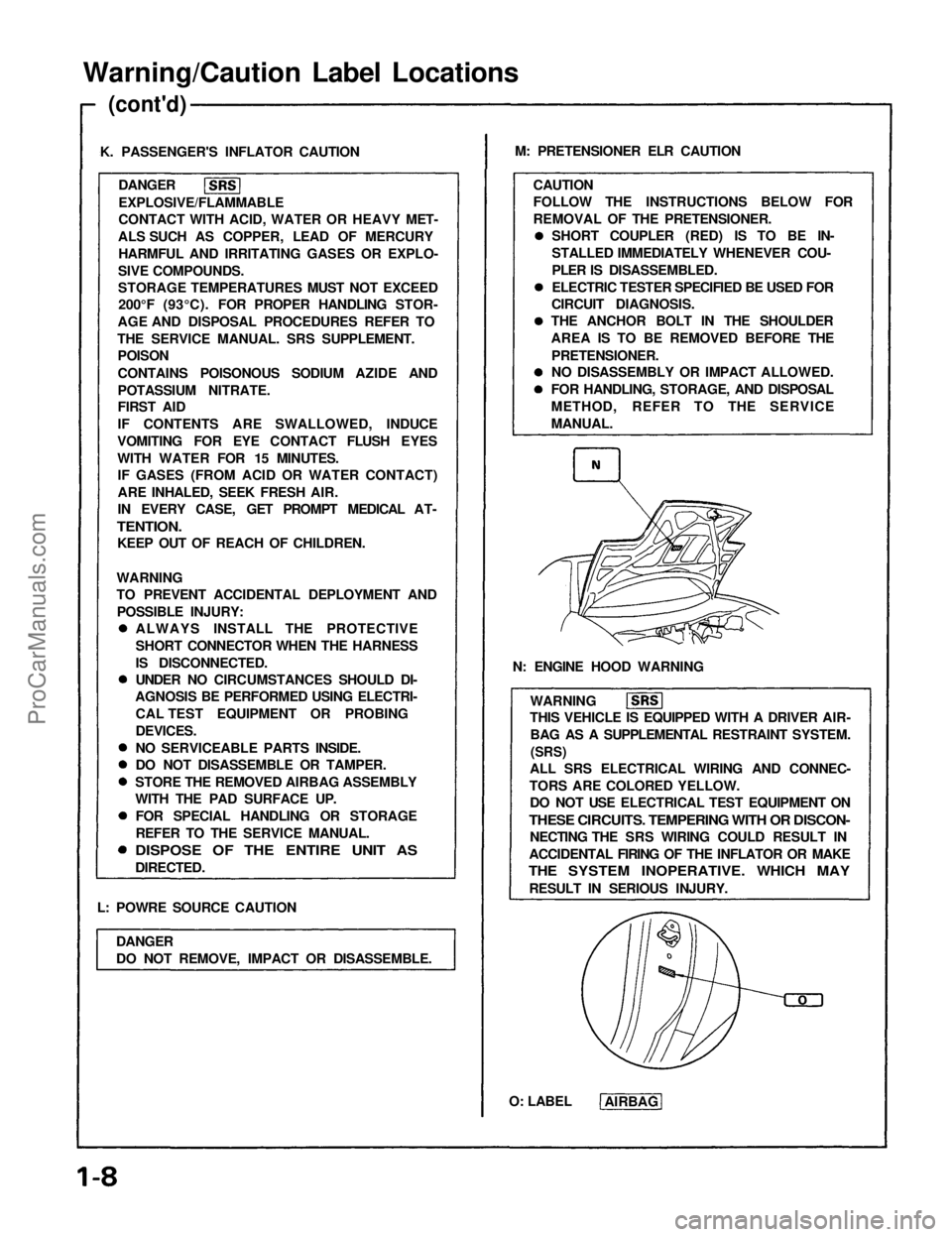
Warning/Caution Label Locations
(cont'd)
K. PASSENGER'S INFLATOR CAUTION DANGER
EXPLOSIVE/FLAMMABLE
CONTACT WITH ACID, WATER OR HEAVY MET-
ALS SUCH AS COPPER, LEAD OF MERCURY HARMFUL AND IRRITATING GASES OR EXPLO-
SIVE COMPOUNDS.
STORAGE TEMPERATURES MUST NOT EXCEED 200°F (93°C). FOR PROPER HANDLING STOR-
AGE AND DISPOSAL PROCEDURES REFER TO
THE SERVICE MANUAL. SRS SUPPLEMENT. POISON
CONTAINS POISONOUS SODIUM AZIDE AND
POTASSIUM NITRATE.
FIRST AID
IF CONTENTS ARE SWALLOWED, INDUCE
VOMITING FOR EYE CONTACT FLUSH EYES
WITH WATER FOR 15 MINUTES. IF GASES (FROM ACID OR WATER CONTACT)
ARE INHALED, SEEK FRESH AIR.
IN EVERY CASE, GET PROMPT MEDICAL AT-
TENTION.
KEEP OUT OF REACH OF CHILDREN.
L: POWRE SOURCE CAUTION DANGER
DO NOT REMOVE, IMPACT OR DISASSEMBLE. M: PRETENSIONER ELR CAUTION
CAUTION
FOLLOW THE INSTRUCTIONS BELOW FOR
REMOVAL OF THE PRETENSIONER.
N: ENGINE HOOD WARNING WARNING
THIS VEHICLE IS EQUIPPED WITH A DRIVER AIR-
BAG AS A SUPPLEMENTAL RESTRAINT SYSTEM.
(SRS)
ALL SRS ELECTRICAL WIRING AND CONNEC-
TORS ARE COLORED YELLOW. DO NOT USE ELECTRICAL TEST EQUIPMENT ON
THESE CIRCUITS. TEMPERING WITH OR DISCON-
NECTING THE SRS WIRING COULD RESULT IN
ACCIDENTAL FIRING OF THE INFLATOR OR MAKE
THE SYSTEM INOPERATIVE. WHICH MAY
RESULT IN SERIOUS INJURY.
O: LABEL AIRBAG
WARNING
TO PREVENT ACCIDENTAL DEPLOYMENT AND
POSSIBLE INJURY: ALWAYS INSTALL THE PROTECTIVE
SHORT CONNECTOR WHEN THE HARNESS
IS DISCONNECTED.
UNDER NO CIRCUMSTANCES SHOULD DI-
AGNOSIS BE PERFORMED USING ELECTRI-
CAL TEST EQUIPMENT OR PROBING
DEVICES.
NO SERVICEABLE PARTS INSIDE.
DO NOT DISASSEMBLE OR TAMPER.
STORE THE REMOVED AIRBAG ASSEMBLY
WITH THE PAD SURFACE UP. FOR SPECIAL HANDLING OR STORAGE
REFER TO THE SERVICE MANUAL.
DISPOSE OF THE ENTIRE UNIT AS
DIRECTED. SHORT COUPLER (RED) IS TO BE IN-
STALLED IMMEDIATELY WHENEVER COU-
PLER IS DISASSEMBLED.
ELECTRIC TESTER SPECIFIED BE USED FOR
CIRCUIT DIAGNOSIS.
THE ANCHOR BOLT IN THE SHOULDER
AREA IS TO BE REMOVED BEFORE THE
PRETENSIONER.
NO DISASSEMBLY OR IMPACT ALLOWED.
FOR HANDLING, STORAGE, AND DISPOSAL
METHOD, REFER TO THE SERVICE
MANUAL.ProCarManuals.com
Page 1308 of 1640
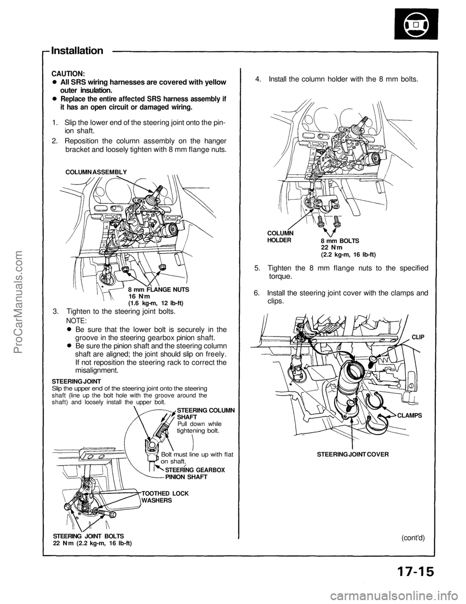
Installation
CAUTION:
All SRS wiring harnesses are covered with yellow
outer insulation.
Replace the entire affected SRS harness assembly if
it has an open circuit or damaged wiring.
1. Slip the lower end of the steering joint onto the pin- ion shaft.
2. Reposition the column assembly on the hanger bracket and loosely tighten with 8 mm flange nuts.
COLUMN ASSEMBLY
8 mm FLANGE NUTS
16 N.m
(1.6 kg-m, 12 lb-ft)
3. Tighten to the steering joint bolts.
NOTE:
Be sure that the lower bolt is securely in the
groove in the steering gearbox pinion shaft. Be sure the pinion shaft and the steering column
shaft are aligned; the joint should slip on freely.
If not reposition the steering rack to correct the
misalignment.
STEERING JOINT
Slip the upper end of the steering joint onto the steering
shaft (line up the bolt hole with the groove around the
shaft) and loosely install the upper bolt. STEERING COLUMN
SHAFTPull down while
tightening bolt.
Bolt must line up with flat
on shaft.
STEERING GEARBOX
PINION SHAFT
TOOTHED LOCK
WASHERS
STEERING JOINT BOLTS
22 N ·
m (2.2 kg-m, 16 Ib-ft) 4. Install the column holder with the 8 mm bolts.
COLUMN
HOLDER
8 mm BOLTS
22 N.m
(2.2 kg-m, 16 Ib-ft)
5. Tighten the 8 mm flange nuts to the specified
torque.
6. Install the steering joint cover with the clamps and clips.
CLIP
STEERING JOINT COVER
CLAMPS
(cont'd)ProCarManuals.com
Page 1378 of 1640
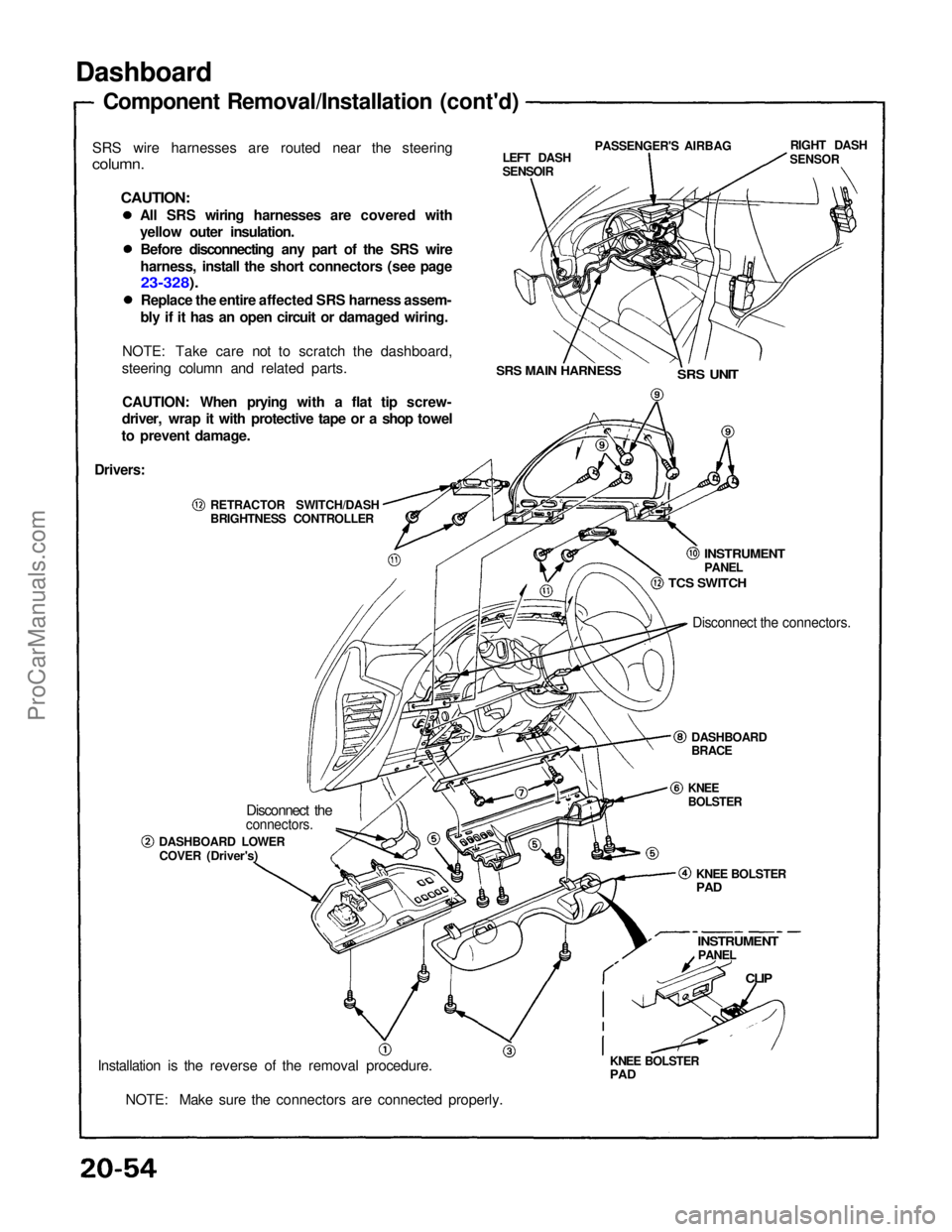
Dashboard
Component Removal/Installation (cont'd)
SRS wire harnesses are routed near the steering
column.
CAUTION:
All SRS wiring harnesses are covered with
yellow outer insulation.Before disconnecting any part of the SRS wire
harness, install the short connectors (see page
23-328).
Replace the entire affected SRS harness assem-
bly if it has an open circuit or damaged wiring.
NOTE: Take care not to scratch the dashboard,
steering column and related parts.
CAUTION: When prying with a flat tip screw-
driver, wrap it with protective tape or a shop towel
to prevent damage. LEFT DASH
SENSOIR
PASSENGER'S AIRBAG
RIGHT DASH
SENSOR
SRS MAIN HARNESS
SRS UNIT
Drivers:
RETRACTOR SWITCH/DASH
BRIGHTNESS CONTROLLER
INSTRUMENT
PANEL
TCS SWITCH
Disconnect the connectors.
DASHBOARD
BRACE
KNEE
BOLSTER
KNEE BOLSTER
PAD
INSTRUMENT
PANEL
CLIP
KNEE BOLSTER
PAD
Disconnect the
connectors.
DASHBOARD LOWER COVER (Driver's)
Installation is the reverse of the removal procedure. NOTE: Make sure the connectors are connected properly.ProCarManuals.com