1991 ACURA NSX timing belt
[x] Cancel search: timing beltPage 83 of 1640
Rocker Arms
Manual Inspection
1. Remove the ignition coil covers (see page 6-15 ('91-'93) or ('94-'96)
2. Remove the ignition coils (see page 6-15 ('91-'93)or ('94-'96).
3. Remove the cylinder head covers.
NOTE: Refer to pages 6-47 ('91-'93)
or ('94-'96) ,48 ('91-'93)
or ('94-'96) when installing the cylinder head cover.
4. Set the No. 1 piston at top dead center (TDC) (see
page 6-19 ('91-'93)
or ('94-'96).
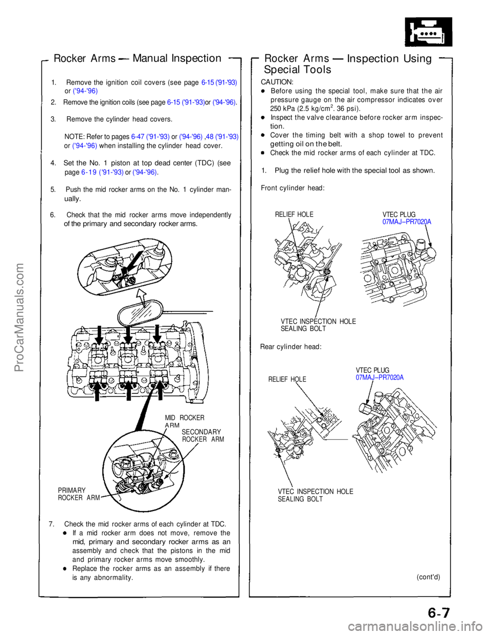
5. Push the mid rocker arms on the No. 1 cylinder man-
ually.
6. Check that the mid rocker arms move independently
of the primary and secondary rocker arms.
MID ROCKER
ARM
SECONDARY
ROCKER ARM
PRIMARY
ROCKER ARM
7. Check the mid rocker arms of each cylinder at TDC. If a mid rocker arm does not move, remove the
mid, primary and secondary rocker arms as an
assembly and check that the pistons in the mid
and primary rocker arms move smoothly.
Replace the rocker arms as an assembly if there
is any abnormality. Rocker Arms
Inspection Using
Special Tools
CAUTION:
Before using the special tool, make sure that the air
pressure gauge on the air compressor indicates over
250 kPa (2.5 kg/cm2. 36 psi). Inspect the valve clearance before rocker arm inspec-
tion.
Cover the timing belt with a shop towel to prevent
getting oil on the belt.
Check the mid rocker arms of each cylinder at TDC.
1. Plug the relief hole with the special tool as shown.
Front cylinder head:
RELIEF HOLE
VTEC PLUG
07MAJ–PR7020A
VTEC INSPECTION HOLE
SEALING BOLT
Rear cylinder head:
RELIEF HOLE
VTEC PLUG
07MAJ–PR7020A
VTEC INSPECTION HOLE
SEALING BOLT
(cont'd)ProCarManuals.com
Page 84 of 1640
Valve Clearance
Adjustment
NOTE:
Valves should be adjusted cold, when the cylinderhead temperature is less than 100°F (38°C).
Adjustment is the same for both intake and exhaust valves.
Adjust valve clearance at TDC of each cylinder.
Do not rotate the engine counterclockwise. The tim-
ing belt could jump a tooth on the camshaft pulleys.
1. Remove the cylinder head covers.
NOTE: Refer to pages 6-47 ('91-'93),or ('94-'96), 6-48
('91-'93), or ('94-'96) when installing the cylinder head cover.
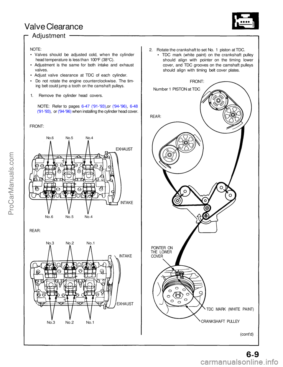
FRONT:
No.6 No.5 No.4
EXHAUST
INTAKE
No.6 No.5 No.4
REAR:
No.3 No.2 No.1
INTAKE
EXHAUST
No.3 No.2 No.1 (cont'd)
CRANKSHAFT PULLEY
TDC MARK (WHITE PAINT)
POINTER ON
THE LOWER
COVER
REAR:
Number 1 PISTON at TDC
FRONT:
2. Rotate the crankshaft to set No. 1 piston at TDC.
TDC mark (white paint) on the crankshaft pulley
should align with pointer on the timing lower
cover, and TDC grooves on the camshaft pulleysshould align with timing belt cover plates.ProCarManuals.com
Page 88 of 1640

Timing Belt
Illustrated Index
NOTE:
Refer to page 6-18 ('91-'93) or ('94-'96) for positioning crankshaft and pulley before installing the belt.
if it is to be reused, mark the direction of rotation on the belt before removing.
Do not use the middle cover and lower cover for storing removed items.
Clean the middle cover and lower cover before installing.
Replace the camshaft seals and crankshaft seals if there is oil leakage.
Refer to page 6-12 ('91-'93) or ('94-'96) before installing timing belt.
CYLINDER HEAD COVER
Refer to page 6-47 ('91-'93) or ('94-'96)
when installing
RUBBER SEALS
Replace when damaged
or deteriorated.
6 x 1.0 mm
12N·m (1.2 kg-m,
9 Ib-ft)
6 x 1.0 mm
12N·m (1.2 kg-m.
9 Ib-ft)
MIDDLE
COVER
RUBBER SEALS
Replace when damaged
or deteriorated.
LOWER COVER
6 x 1.0 mm
12 N·m
(1.2
kg-m,
9 Ib-ft)
CRANKSHAFT
PULLEY
Replacement,
page 6-12 ('91-'93) or ('94-'96)
PULLEY BOLT
16x 1.5 mm
250 N·m
(25.0 kg-m. 181 Ib-ft)
Replacement,
page 6-12 ('91-'93)
or ('94-'96)
Do not use an impact
wrench when installing.
HEAD COVER GASKET
Replace when leaking,
damaged or deteriorated.
Apply liquid gasket at
the eight corners of the
ecesses
CAP NUT
6 x 1.0 mm
10N m (1.0 kg-m,
7 Ib-ft)
WASHERS
Replace when damaged
or deteriorated.
RUBBER SEALS
Replace when damaged
or deteriorated.
ADJUSTING BOLT
10 x
1.25
mm
43N.m (4.3 kg-m.31 Ib-ft)
For adjustment only,
do not remove.
COLLARS
TIMING BELTInspection, page 6-14 ('91-'93) or ('94-'96)
Adjustment, page 6-14 ('91-'93) or ('94-'96)
Install with concave
surface facing out.
6 x 1.0 mm
12N·m (1.2 kg-m, 9 Ib-ft)ProCarManuals.com
Page 89 of 1640

Timing Belt
Inspection
1. Remove the ignition coil covers and harness clamps.
2. Disconnect the connectors, then remove the ignition
coils.
3. Remove the cylinder head covers,
4. Inspect the timing belt for cracks and coolant or oil soaking.
NOTE:
Replace the belt if coolant or oil soaked.
Remove any oil or solvent that gets on the belt.
Inspect this area
for wear.
Rotate pulley and
Inspect belt.
Tension Adjustment
CAUTION:
Always adjust timing belt tension with the engine cold
Do not rotate the crankshaft when the adjusting bolt
is loose (the timing belt will skid over the teeth of
the rear intake caimshaft pulley).
Adjust the belt tension only when the belt has been
removed and reinstalled or replaced.
NOTE:
Tensioner is spring-loaded to apply proper tension to
the belt automatically after making the following ad-
justment. Inspect the timing belt before adjusting the belt
tension.
Always rotate the crankshaft clockwise. Rotating it
counterclockwise may result in improper adjustment
of the belt tension or cause the belt to jump a tooth
on the camshaft pulleys.
Install the timing beIt with the No. 1 piston at TDC
(see pages 6-18 ('91-'93) or ('94-'96),19 ('91-'93)
or ('94-'96) Remove the slack in the sequence of , and
by turning each camshaft pulley slightly.
Loosen the timing belt adjusting bolt 180° (the slack
at should be eliminated).
Then, tighten the timing belt adjusting bolt.
Verify that No. 1 piston is at TDC (see page 6-19).
Rotate the crankshaft clockwise nine teeth on the
camshaft pulley (The blue mark on the crankshaft pul- ley should line up with the pointer on lower cover).
Loosen
the
timing
belt
adjusting
bolt.
Retighten the adjusting bolt, torque to 43 N·m (4.3
kg-m, 31 Ib-fl).
Direction
of rotation
POINTER ON
LOWER COVER
ADJUSTING BOLT
43N·m (4.3 kg-m,
31 Ib-ft)
BLUE MARK
TDC MARK
ProCarManuals.com
Page 90 of 1640
Removal
NOTE:
Before removing the belt, turn the crankshaft pulley
so the No. 8 piston is at top dead center (TDC) (see
page 6-19 ('91-'93) or ('94-'96)
Inspect the water pump after removing the timing
belt (see page 10-11).
If it is to be reused, mark the direction of rotation on
the belt.
1. Disconnect the battery negative terminal first, then the positive terminal,
2. Remove the right rear wheel/tire.
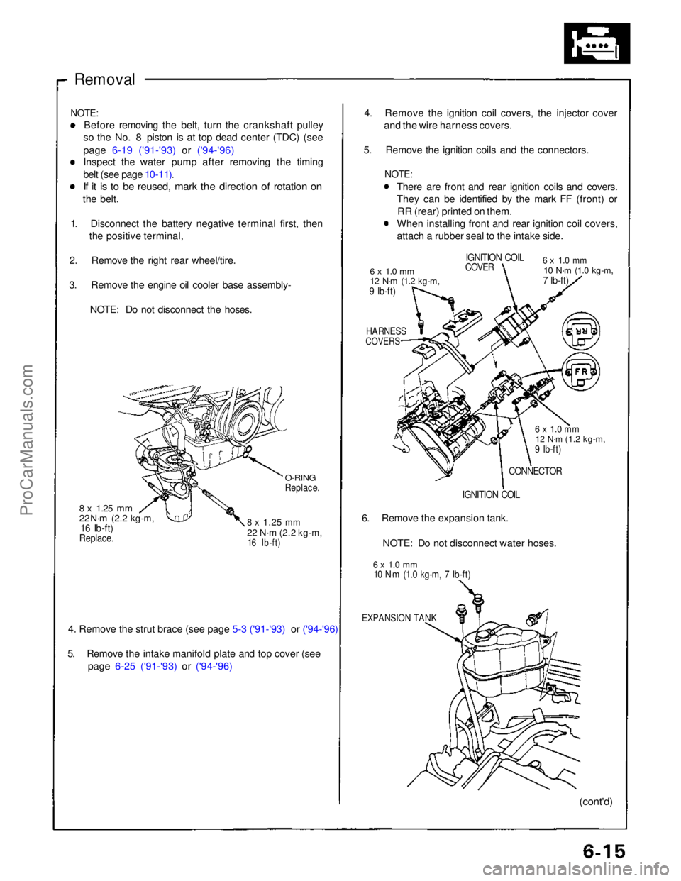
3. Remove the engine oil cooler base assembly- NOTE: Do not disconnect the hoses.
O-RING
Replace.
8 x
1.25
mm
22 N·m
(2.2 kg-m,
16 Ib-ft)
8 x
1.25
mm
22 N·m
(2.2 kg-m,
16 Ib-ft)
Replace.
4. Remove the strut brace (see page 5-3 ('91-'93) or ('94-'96)
5. Remove the intake manifold plate and top cover (see
page 6-25 ('91-'93) or ('94-'96)
4. Remove the ignition coil covers, the injector cover
and the wire harness covers.
5. Remove the ignition coils and the connectors.
NOTE:
There are front and rear ignition coils and covers.
They can be identified by the mark FF (front) orRR (rear) printed on them.
When installing front and rear ignition coil covers,
attach a rubber seal to the intake side.
6 x 1.0 mm
12 N·m
(1.2 kg-m,
9 Ib-ft)
IGNITION COIL
COVER
6 x 1.0 mm
10 N·m
(1.0 kg-m,
7 Ib-ft)
HARNESS
COVERS
6 x 1.0 mm
12 N·m
(1.2 kg-m,
9 Ib-ft)
CONNECTOR
IGNITION COIL
6. Remove the expansion tank.
NOTE: Do not disconnect water hoses.
6 x 1.0 mm
10 N·m (1.0 kg-m, 7 Ib-ft)
EXPANSION TANK
(cont'd)ProCarManuals.com
Page 91 of 1640
Timing Belt
Removal (cont'd)
7. Remove the breather hose and the air cleaner hous-
in
g
(see page 6-25 ('91-'93) or ('94-'96) )
8. Disconnect the alternator connector and the termi-
nal.
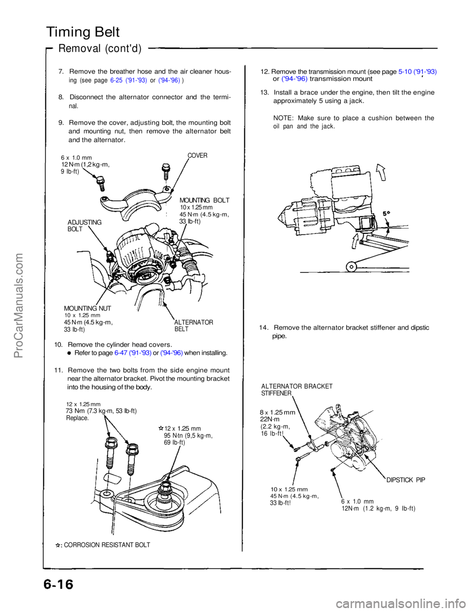
9. Remove the cover, adjusting bolt, the mounting bolt and mounting nut, then remove the alternator belt
and the alternator.
COVER
6 x 1.0 mm
12 N·m
(1,2 kg-m,
9 Ib-ft)
MOUNTING BOLT
10 x 1.25 mm
45 N·m
(4.5 kg-m,
33 Ib-ft)
ADJUSTING
BOLT
MOUNTING NUT
10 x
1.25
mm
45 N·m
(4.5 kg-m,
33 Ib-ft)
ALTERNATOR
BELT
10. Remove the cylinder head covers.
Refer to page 6-47 ('91-'93) or ('94-'96) when installing.
11. Remove the two bolts from the side engine mount
near the alternator bracket. Pivot the mounting bracket
into the housing of the body.
12 x 1.25 mm
73 N·m (7.3 kg-m, 53 Ib-ft)
Replace.
12 x
1.25
mm
95 N·tn (9,5 kg-m,
69 Ib-ft)
CORROSION RESISTANT BOLT
12. Remove the transmission mount (see page 5-10 ('91-'93)
or ('94-'96) transmission mount
13. Install a brace under the engine, then tilt the engine
approximately 5 using a jack.
NOTE: Make sure to place a cushion between the
oil pan and the jack.
14. Remove the alternator bracket stiffener and dipstic
pipe.
ALTERNATOR BRACKET
STIFFENER
8 x
1.25
mm
22N·m
(2.2 kg-m,
16 lb-ft!
10 x
1.25
mm
45 N·m
(4.5 kg-m,
33 Ib-ft!
6 x 1.0 mm
12N·m (1.2 kg-m, 9 Ib-ft)
DIPSTICK PIPProCarManuals.com
Page 92 of 1640
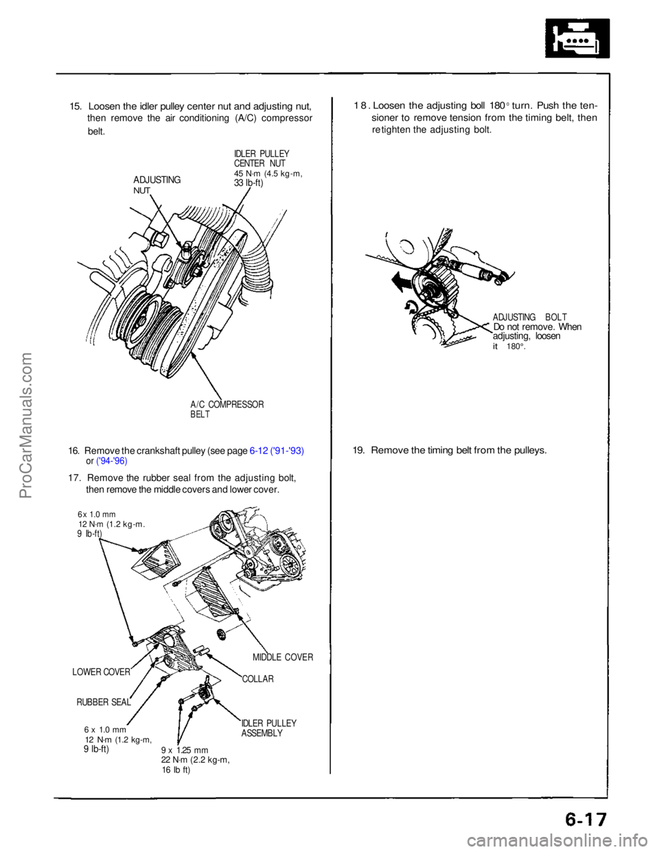
15. Loosen the idler pulley center nut and adjusting nut,
then remove the air conditioning (A/C) compressor
belt.
IDLER PULLEY
CENTER NUT
45 N·m
(4.5 kg-m,
33 lb-ft)
ADJUSTING
NUT
A/C COMPRESSOR
BELT
16. Remove the crankshaft pulley (see page 6-12 ('91-'93)
or ('94-'96)
17. Remove the rubber seal from the adjusting bolt,
then remove the middle covers and lower cover.
6 x 1.0 mm
12 N·m
(1.2 kg-m.
9 Ib-ft)
LOWER COVER RUBBER SEAL
6 x 1.0 mm
12 N·m
(1.2 kg-m,
9 lb-ft)
9 x
1.25
mm
22 N·m
(2.2 kg-m,
16 Ib ft)
IDLER PULLEY
ASSEMBLYCOLLAR
MIDDLE COVER
18. Loosen the adjusting boll 180
0
turn. Push the ten-
sioner to remove tension from the timing belt, then
re tighten the adjusting bolt.
ADJUSTING BOLT
Do not remove. When
adjusting, loosen
it
180°.
19. Remove the timing belt from the pulleys.ProCarManuals.com
Page 93 of 1640
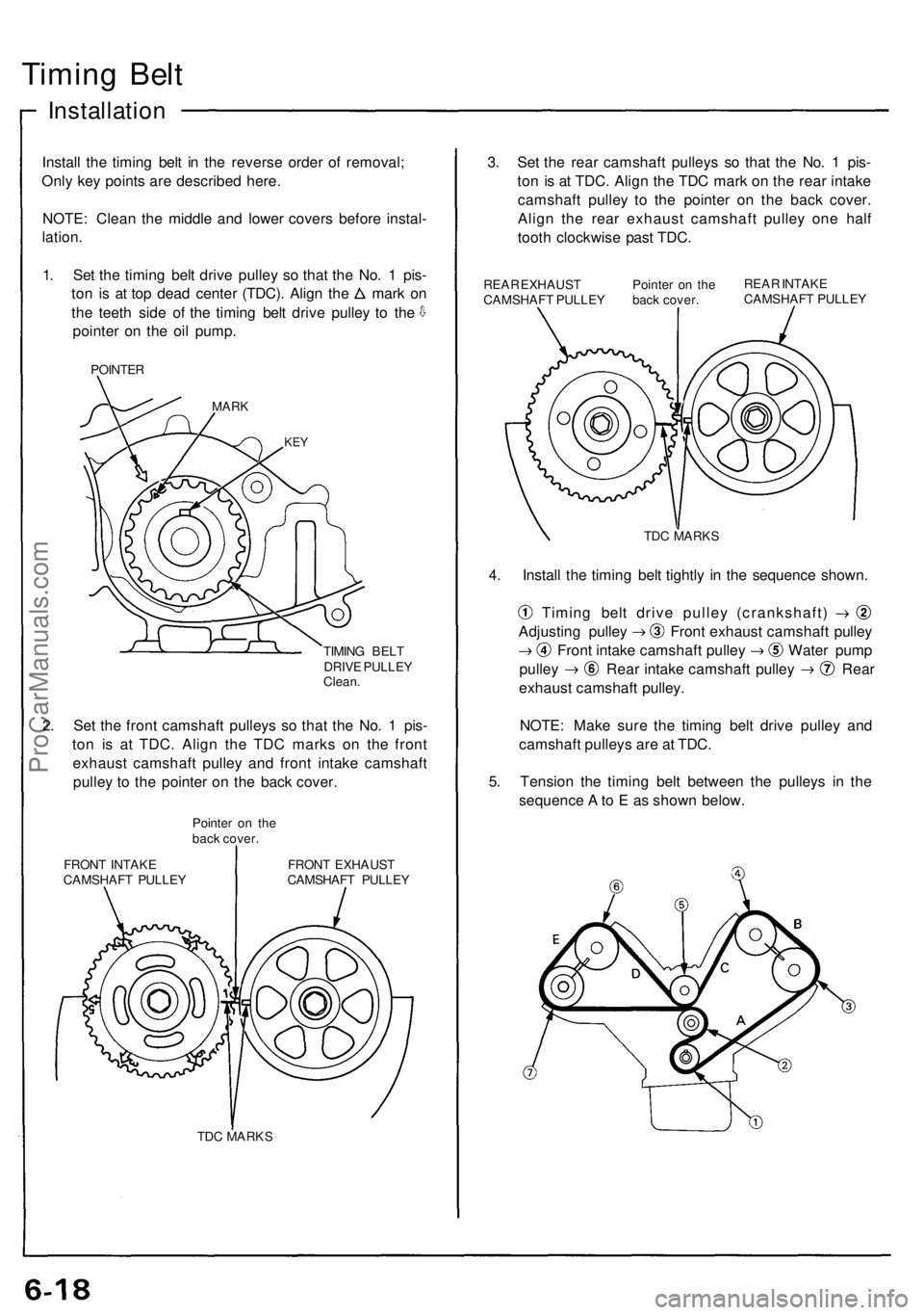
Timing Belt
Installation
Install the timing belt in the reverse order of removal;
Only key points are described here.
NOTE: Clean the middle and lower covers before instal-
lation.
1. Set the timing belt drive pulley so that the No. 1 pis-
ton is at top dead center (TDC). Align the mark on
the teeth side of the timing belt drive pulley to the
pointer on the oil pump.
POINTER
MARK
KEY
TIMING BELT
DRIVE PULLEY
Clean.
2. Set the front camshaft pulleys so that the No. 1 pis-
ton is at TDC. Align the TDC marks on the front
exhaust camshaft pulley and front intake camshaft
pulley to the pointer on the back cover.
Pointer on the
back cover.
FRONT INTAKE
CAMSHAFT PULLEY
FRONT EXHAUST
CAMSHAFT PULLEY
TDC MARKS
3. Set the rear camshaft pulleys so that the No. 1 pis-
ton is at TDC. Align the TDC mark on the rear intake
camshaft pulley to the pointer on the back cover.
Align the rear exhaust camshaft pulley one half
tooth clockwise past TDC.
REAR EXHAUST
CAMSHAFT PULLEY
Pointer on the
back cover.
REAR INTAKE
CAMSHAFT PULLEY
TDC MARKS
4. Install the timing belt tightly in the sequence shown.
Timing belt drive pulley (crankshaft)
Adjusting pulley Front exhaust camshaft pulley
Front intake camshaft pulley Water pump
pulley Rear intake camshaft pulley Rear
exhaust camshaft pulley.
NOTE: Make sure the timing belt drive pulley and
camshaft pulleys are at TDC.
5. Tension the timing belt between the pulleys in the
sequence A to E as shown below.ProCarManuals.com