1991 ACURA NSX low oil pressure
[x] Cancel search: low oil pressurePage 72 of 1640
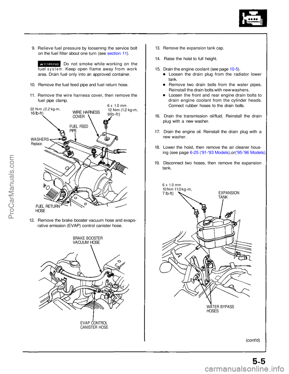
9. Relieve fuel pressure by loosening the service bolt
on the fuel filter about one turn (see section 11).
Do not smoke while working on the
fuel
system.
Keep open flame away from work
area. Drain fuel only into an approved container.
10. Remove the fuel feed pipe and fuel return hose.
11. Remove the wire harness cover, then remove the fuel pipe clamp.
22 N·m
(2.2 kg-m,
16 Ib-ft)
WIRE HARNESS
COVER
6 x 1.0 mm
12 N·m
(1.2 kg-m,
9 lb-ft)
FUEL FEED
PIPE
WASHERS
Replace.
FUEL RETURN
HOSE
12. Remove the brake booster vacuum hose and evapo- rative emission (EVAP) control canister hose.
BRAKE BOOSTER
VACUUM HOSE
EVAP CONTROL
CANISTER HOSE
13. Remove the expansion tank cap.
14. Raise the hoist to full height.
15. Drain the engine coolant (see page
10-5).
Loosen the drain plug from the radiator lower
tank. Remove two drain bolls from the water pipes.
Reinstall the drain bolts with new washers.
Loosen the front and rear engine drain bolts to
drain engine coolant from the cylinder heads.
Connect rubber hoses to the drain bolts.
16. Drain the transmission oil/fluid. Reinstall the drain plug with a new washer.
17. Drain the engine oil. Reinstall the drain plug with a
new washer.
18. Lower the hoist, then remove the air cleaner hous-
ing (see page 6-25 ('91-'93 Mode ls),or('95-'96 Models).
19. Disconnect two hoses, then remove the expansion
tank.
6 x 1.0 mm
10 N·m
11.0 kg-m,
7 lb-ft)
EXPANSION
TANK
WATER BYPASS
HOSES
(cont'd)ProCarManuals.com
Page 97 of 1640
![ACURA NSX 1991 Service Repair Manual
Cylinder Heads
Illustrated Index (cont'd)
CAUTION:
To
avoid
damage,
wait
until
the
engine
coolant
temperature
drops
below
100°F
(39-C]
before
removing
the
cylin-
der head.
N ACURA NSX 1991 Service Repair Manual
Cylinder Heads
Illustrated Index (cont'd)
CAUTION:
To
avoid
damage,
wait
until
the
engine
coolant
temperature
drops
below
100°F
(39-C]
before
removing
the
cylin-
der head.
N](/manual-img/32/56988/w960_56988-96.png)
Cylinder Heads
Illustrated Index (cont'd)
CAUTION:
To
avoid
damage,
wait
until
the
engine
coolant
temperature
drops
below
100°F
(39-C]
before
removing
the
cylin-
der head.
NOTE: Use new O-rings and gaskets when reassembling.
Prior to reassembling, clean all the parts in solvent, dry them, and apply lubricant to any contact parts.
REAR VARIABLE VALVE TIMING
AND VALVE LIFT ELECTRONIC CONTROL
SYSTEM (VTEC) SOLENOID VALVE
Troubleshooting, page 6-3 ('91-'93) or ('94-'96)
EXHAUST GAS
RECIRCULATI0N (EGR) VALVE
6 x 1 .0 mm
12 N·m
(1.2 kg-m.
9 Ib-ft)
8 x
1.25
mm
22 N·m
(2.2 kg-m,
16 Ib-ft)
ENGINE COOLANT
TEMPERATURE (ECT) SENSOR
18 N·m (1.8 kg-m, 13 Ib-ft)
8 x
1.25
mm
22 N·m (2.2 kg-m. 16 lb-ft)
FRONT VTEC SOLENOID VALVE
Troubleshooting. page 6-3
SEALING BOLTS
60 N·m
(6.0 kg-m,
43 lb-ft)
OIL PRESSURE
GAUSE SENDING
UNIT (section 23)
ROCKER
SHAFTS
WASHERS
Replace.
8 x
1.25
mm
22 N·m
(2.2 kg-m,16 Ib-ft)
DOWEL PIN
0-RING
Replace.
ECT SWITCH
28 N·m
12.8 kg-m.
20 lb-ft
O-RING
Replace.
O-RING
Replace.
ROCKER ARM ASSEMBLY[PRIMARY. MID, SECONDARY]
Inspection, page 6-32 ('91-'93) or ('94-'96)
ROCKER SHAFT
OIL CONTROL
ORIFICE
Remove with 5 mm
boit and clean.
FILTER
Replace.
GASKET
Replace.
O-RING
Replace.ProCarManuals.com
Page 230 of 1640
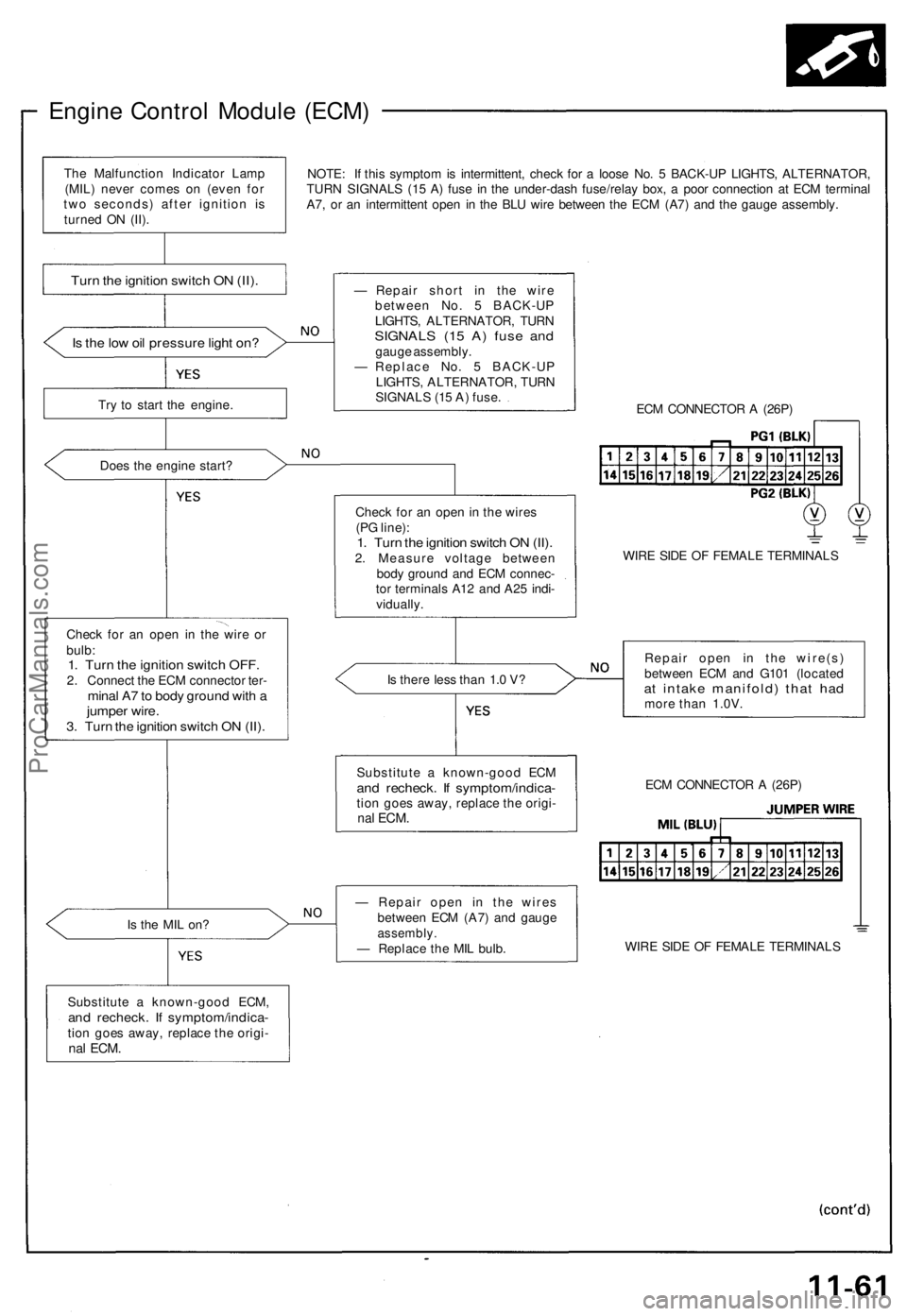
Engine Control Module (ECM)
NOTE: If this symptom is intermittent, check for a loose No. 5 BACK-UP LIGHTS, ALTERNATOR,
TURN SIGNALS (15 A) fuse in the under-dash fuse/relay box, a poor connection at ECM terminal
A7, or an intermittent open in the BLU wire between the ECM (A7) and the gauge assembly.
Is the low oil pressure light on?
Try to start the engine.
Does the engine start?
Check for an open in the wire or
bulb:
1. Turn the ignition switch OFF.
2. Connect the ECM connector ter-
minal A7 to body ground with a
jumper wire.
3. Turn the ignition switch ON (II).
Is the MIL on?
Substitute a known-good ECM,
and recheck. If symptom/indica-
tion goes away, replace the origi-
nal
ECM.
— Repair short in the wire
between No. 5 BACK-UP
LIGHTS, ALTERNATOR, TURN
SIGNALS (15 A) fuse and
gauge assembly.
— Replace No. 5 BACK-UP
LIGHTS, ALTERNATOR, TURN
SIGNALS (15 A) fuse.
ECM CONNECTOR A (26P)
Check for an open in the wires
(PG line):
1. Turn the ignition switch ON (II).
2. Measure voltage between
body ground and ECM connec-
tor terminals A12 and A25 indi-
vidually.
WIRE SIDE OF FEMALE TERMINALS
Is there less than 1.0 V?
Repair open in the wire(s)
between ECM and G101 (located
at intake manifold) that had
more than 1.0V.
— Repair open in the wires
between ECM (A7) and gauge
assembly.
— Replace the MIL bulb.
WIRE SIDE OF FEMALE TERMINALS
ECM CONNECTOR A (26P)
Substitute a known-good ECM
and recheck. If symptom/indica-
tion goes away, replace the origi-
nal
ECM.
Turn the ignition switch ON (II).
The Malfunction Indicator Lamp
(MIL) never comes on (even for
two seconds) after ignition is
turned ON (II).ProCarManuals.com
Page 705 of 1640
A/C Servic e Tip s an d Precaution s
The ai r conditionin g syste m use s HFC-134 a (R-134a ) refrigeran t an d polyalkyleneglyco l (PAG ) refrigeran t oi l (ND-OI L
8 : P/ N 38899-PR7-A01) , whic h ar e no t compatibl e wit h CFC-1 2 (R-12 ) refrigeran t an d minera l oil . D o no t us e R-1 2 refriger -
an t o r minera l oi l i n thi s system , an d d o no t attemp t t o us e R-1 2 servicin g equipment ; damag e t o th e ai r conditionin g
system o r you r servicin g equipmen t wil l result .
Only us e servic e equipmen t tha t i s U.L.-liste d an d i s certifie d t o mee t th e requirement s o f SA E J221 0 t o remov e R-134a;
fro m th e ai r conditione r system .
CAUTION : Exposur e to ai r conditione r refrigeran t an d lubrican t vapo r o r mis t ca n irritat e eyes , nos e an d throat , Avoi d
breathin g th e ai r conditione r refrigeran t an d lubrican t vapo r o r mist .
I f accidenta l syste m discharg e occurs , ventilat e wor k are a befor e resumin g service .
R-134 a servic e equipmen t o r vehicl e ai r conditione r system s shoul d no t b e pressur e teste d o r lea k teste d wit h compresse d
air.
Som e mixture s o f ai r an d R-134 a hav e bee n show n to b e combustibl e elevate d pressure s an d ca n resul t
i n fir e o r explosio n causin g injur y o r propert y damage . Neve r us e compresse d ai r t o pressur e tes t R-134 a servic e
equipmen t o r vehicl e ai r conditionin g systems .
Additiona l healt h an d safet y informatio n ma y b e obtaine d fro m th e refrigeran t an d lubrican t manufacturers .
1 . Alway s disconnec t th e negativ e cabl e fro m th e batter y wheneve r replacin g ai r conditionin g parts .
2 . Kee p moistur e an d dus t ou t o f th e system . Whe n disconnectin g an y lines , plu g o r cap the fitting s immediately ; don' t
remov e th e cap s o r plug s unti l jus t befor e yo u reconnec t eac h line .
3 . Befor e connectin g an y hos e o r line , appl y a fe w drop s o f refrigeran t oi l (ND-OI L 8 ) t o th e O-ring .
4. Whe n tightenin g o r loosenin g a fitting , us e a secon d wrenc h t o suppor t th e matchin g fitting .
5. Whe n recoverin g th e system , us e a R-134 a refrigeran t Recovery/Recycling/Chargin g System ; don' t releas e
refrigeran t int o th e atmosphere .
6 . Ad d refrigeran t oi l (ND-OI L 8 ) afte r replacin g th e followin g parts :
NOTE:
• D o no t retur n th e oi l t o th e containe r onc e dispense d an d neve r mi x wit h othe r refrigeran t oil s t o avoi d
contamination .
• Immediatel y afte r usin g th e oil , replac e th e ca p o n th e containe r an d sea l i t t o avoi d moistur e absorption .
• D o no t spil l th e refrigeran t oi l o n th e car ; i t ma y damag e th e paint ; i f th e refrigeran t oi l contact s th e paint , was h i t
of f immediately .
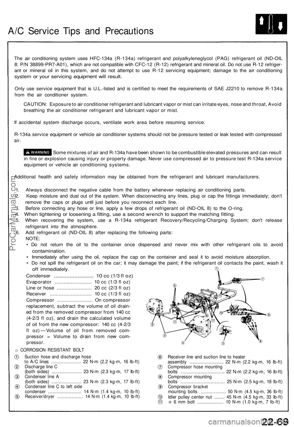
Condenser ........................ . 10 c c (1/ 3 fl oz )
Evaporato r ........................ . 1 0 c c (1/ 3 f l oz )
Lin e o r hos e ....................... . 2 0 c c (2/ 3 f l oz )
Receive r ........................... . 1 0 c c (1/ 3 f l oz )
Compresso r ....................... . O n compresso r
replacement , subtrac t th e volum e o f oi l drain -
e d fro m th e remove d compresso r fro m 14 0 c c
(4-2/ 3 f l oz) , an d drai n th e calculate d volum e
o f oi l fro m th e ne w compressor : 14 0 c c (4-2/ 3
f l oz ) — Volum e o f oi l fro m remove d com -
presso r = Volum e t o drai n fro m ne w com -
pressor .
CORROSIO N RESISTAN T BOL T
Suctio n hos e an d discharg e hos eto A/ C line s ..................... . 2 2 N- m (2. 2 kg-m , 1 6 Ib-ft )Discharg e lin e C(bot h sides ) ..................... . 2 3 N- m (2. 3 kg-m , 1 7 Ib-ft )Condense r lin e A(bot h sides ) ..................... . 2 3 N- m (2. 3 kg-m , 1 7 Ib-ft )Condense r lin e C to lef t sid econdense r ....................... . 1 4 N- m (1. 4 kg-m , 1 0 Ib-ft )Receiver/drye r ................. . 1 4 N- m (1. 4 kg-m , 1 0 Ib-ft )
Receive r lin e an d suctio n lin e t o heate rassembl y ........................ . 2 2 N- m (2. 2 kg-m , 1 6 Ib-ft )Compresso r hos e mountin gbolts .............................. . 2 2 N- m (2. 2 kg-m , 1 6 Ib-ft )Compresso r mountin gbolts .............................. . 2 5 N- m (2. 5 kg-m , 1 8 Ib-ft )Compresso r bracke tmountin g bolt s ................ . 5 0 N- m (4. 5 kg-m , 3 6 Ib-ft )Idler pulle y cente r nu t ....... . 4 5 N- m (4. 5 kg-m , 3 3 Ib-ft )6 m m bol t ................... . 1 0 N- m (1. 0 kg-m , 7 Ib-ft )
ProCarManuals.com
Page 708 of 1640
Recovery
Only use service equipment that is U.L.-listed and is cer-
tified to meet the requirements of SAE J2210 to remove
HFC-134a (R-134a) from the air conditioning system.
CAUTION: Exposure to air conditioner refrigerant
and lubricant vapor or mist can irritate eyes, nose
and throat. Avoid breathing the air conditioner
refrigerant and lubricant vapor or mist.
If accidental system discharge occurs, ventilate work
area before resuming service.
R-134a service equipment or vehicle air conditioning sys-
tem should not be pressure tested or leak tested with
compressed air.
Some mixtures of air and R-134a have
been shown to be combustible at elevated pressures
and can result in fire or explosion causing injury or
property damage. Never use compressed air to pres-
sure test R-134a service equipment or vehicle air
conditioning systems.
Additional health and safety information may be obtained
from the refrigerant and lubricant manufactures.
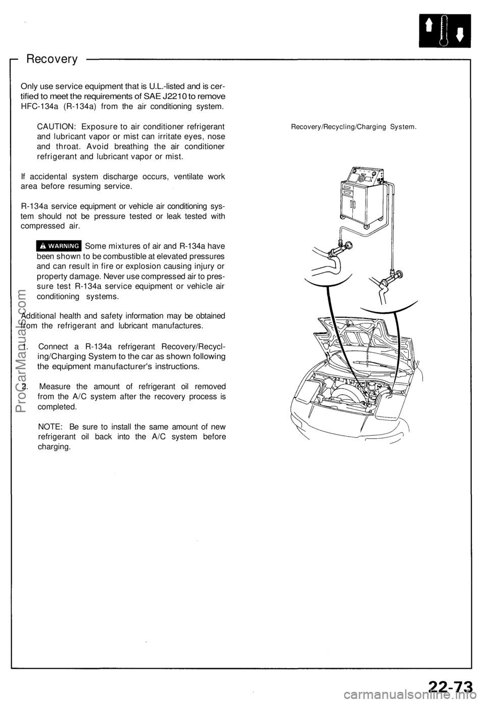
1. Connect a R-134a refrigerant Recovery/Recycl-
ing/Charging System to the car as shown following
the equipment manufacturer's instructions.
2. Measure the amount of refrigerant oil removed
from the A/C system after the recovery process is
completed.
NOTE: Be sure to install the same amount of new
refrigerant oil back into the A/C system before
charging.
Recovery/Recycling/Charging System.ProCarManuals.com
Page 789 of 1640
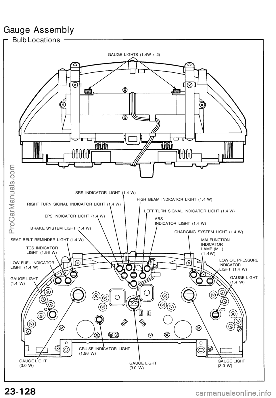
Gauge Assembly
Bulb Locations
GAUGE LIGHTS (1.4W x 2)
SRS INDICATOR LIGHT (1.4 W)
RIGHT TURN SIGNAL INDICATOR LIGHT (1.4 W)
EPS INDICATOR LIGHT (1.4 W)
BRAKE SYSTEM LIGHT (1.4 W)
SEAT BELT REMINDER LIGHT (1.4 W)
TCS INDICATOR
LIGHT (1.96 W)
LOW FUEL INDICATOR
LIGHT (1.4 W)
GAUGE LIGHT
(1.4
W)
HIGH BEAM INDICATOR LIGHT (1.4 W)
LEFT TURN SIGNAL INDICATOR LIGHT (1.4 W)
ABS
INDICATOR LIGHT (1.4 W)
CHARGING SYSTEM LIGHT (1.4 W)
MALFUNCTION
INDICATOR
LAMP (MIL)
(1.4W)
LOW OIL PRESSURE
INDICATOR
LIGHT (1.4 W)
GAUGE LIGHT
(1.4
W)
GAUGE LIGHT
(3.0
W)
GAUGE LIGHT
(3.0
W)
GAUGE LIGHT
(3.0
W)
CRUISE INDICATOR LIGHT
(1.96
W)ProCarManuals.com
Page 1015 of 1640
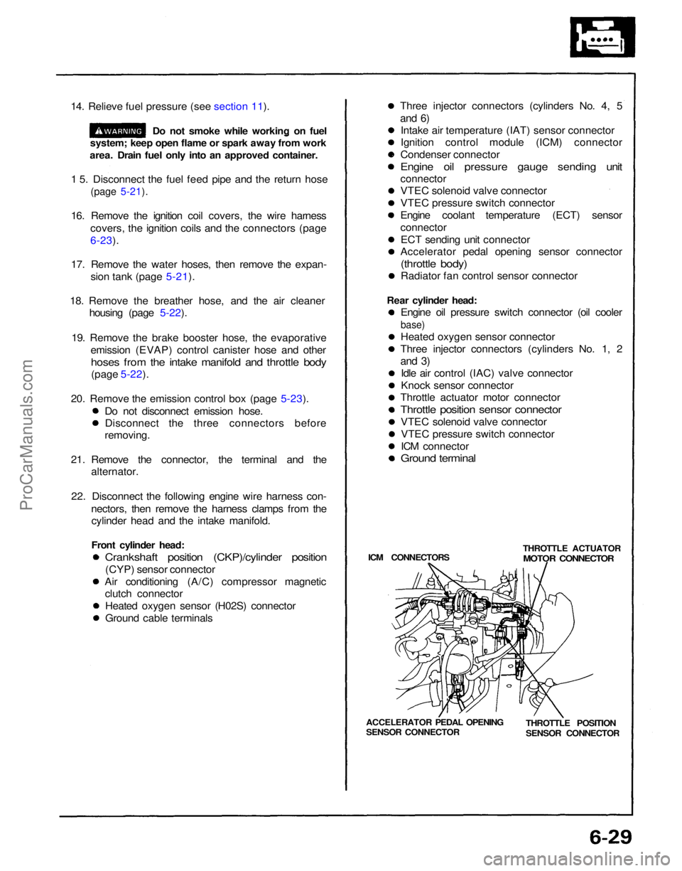
14. Relieve fuel pressure (see section 11).
Do not smoke while working on fuel
system; keep open flame or spark away from work
area. Drain fuel only into an approved container.
1 5. Disconnect the fuel feed pipe and the return hose
(page 5-21).
16. Remove the ignition coil covers, the wire harness covers, the ignition coils and the connectors (page
6-23).
17. Remove the water hoses, then remove the expan- sion tank (page 5-21).
18. Remove the breather hose, and the air cleaner housing (page 5-22).
19. Remove the brake booster hose, the evaporative emission (EVAP) control canister hose and other
hoses from the intake manifold and throttle body
(page 5-22).
20. Remove the emission control box (page 5-23). Do not disconnect emission hose.Disconnect the three connectors before
removing.
21. Remove the connector, the terminal and the alternator.
22. Disconnect the following engine wire harness con- nectors, then remove the harness clamps from thecylinder head and the intake manifold.
Front cylinder head:
Crankshaft position (CKP)/cylinder position
(CYP) sensor connector
Air conditioning (A/C) compressor magnetic clutch connector
Heated oxygen sensor (H02S) connector
Ground cable terminals Three injector connectors (cylinders No. 4, 5
and 6)
Intake air temperature (IAT) sensor connector
Ignition control module (ICM) connector
Condenser connector
Engine oil pressure gauge sending unit
connector
VTEC solenoid valve connector
VTEC pressure switch connector
Engine coolant temperature (ECT) sensor
connector
ECT sending unit connector
Accelerator pedal opening sensor connector
(throttle body)
Radiator fan control sensor connector
Rear cylinder head: Engine oil pressure switch connector (oil cooler
base)
Heated oxygen sensor connector
Three injector connectors (cylinders No. 1, 2
and 3)
Idle air control (IAC) valve connector
Knock sensor connector
Throttle actuator motor connector
Throttle position sensor connector
VTEC solenoid valve connectorVTEC pressure switch connector
ICM connector
Ground terminal
ICM CONNECTORS THROTTLE ACTUATOR
MOTOR CONNECTOR
THROTTLE POSITION
SENSOR CONNECTOR
ACCELERATOR PEDAL OPENING
SENSOR CONNECTORProCarManuals.com
Page 1087 of 1640
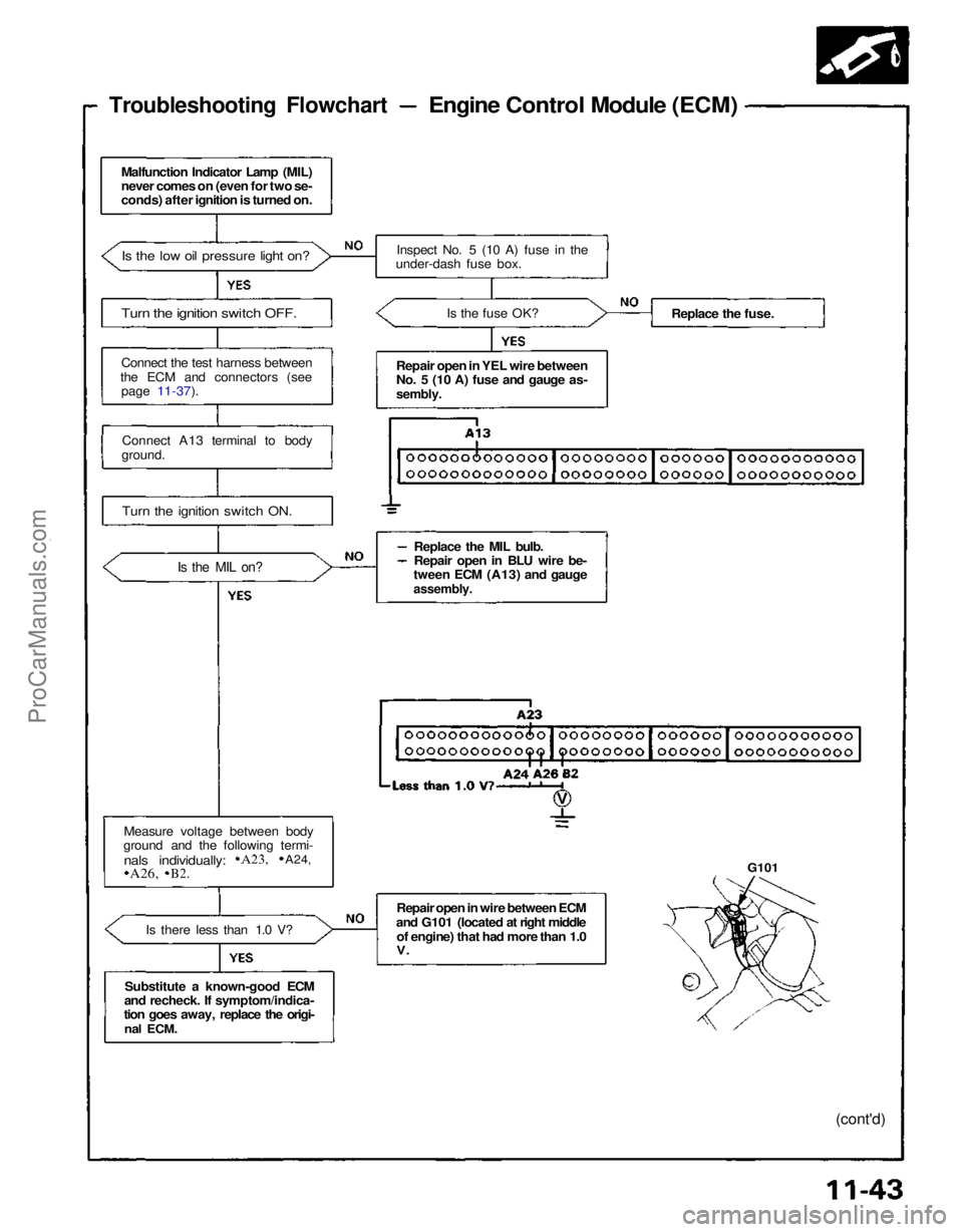
Troubleshooting Flowchart
Engine Control Module (ECM)
Malfunction Indicator Lamp (MIL)
never comes on (even for two se-
conds) after ignition is turned on.
Is the low oil pressure light on?
Turn the ignition switch OFF.
Connect the test harness between
the ECM and connectors (see page 11-37).
Connect A13 terminal to body
ground.
Turn the ignition switch ON.
Is the MIL on?
Measure voltage between body
ground and the following termi-
Is there less than 1.0 V?
Substitute a known-good ECM
and recheck. If symptom/indica-
tion goes away, replace the origi-
nal
ECM. Inspect No. 5 (10 A) fuse in the
under-dash fuse box.
Is the fuse OK?
Repair open in YEL wire between
No. 5 (10 A) fuse and gauge as-
sembly.
Replace the MIL bulb.
Repair open in BLU wire be-
tween ECM (A13) and gauge
assembly.
Repair open in wire between ECM
and G101 (located at right middle of engine) that had more than 1.0
V.
Replace the fuse.
G101
(cont'd)
nals individually:
A23,
A24,
A26,
B2.ProCarManuals.com