Page 692 of 1640
Air Mix Control Motor
Replacement
1. Disconnect the heater valve cable from the air mix control motor.
HEATER VALVE
CABLE
AIR MIX CONTROL
MOTOR
2. Remove the three screws and the air mix control
motor.
AIR MIX CONTROL
MOTOR
3. Install the air mix centrol motor in the reverse order of removal, then apply battery voltage (see page
22-57) and watch the door move.
Make sure that the air mix door moves smoothly
without binding.
Make sure the motor doesn't pull the air mix
door too far.
4. If necessary, to adjust the heater valve cable:
Set the air mix control motor at COOL position
(see page 22-57) with the cable disconnected
at the valve.
Hold the end of the cable housing against the
stop on the cable. Then snap the clamp down
ove
r
the housing.
After adjusting the cable, make sure that the air
mix control motor still moves smoothly without
binding.
STOP
CLAMP
HEATER VALVE
CABLE
AIR MIX CONTROLMOTOR
ProCarManuals.com
Page 693 of 1640
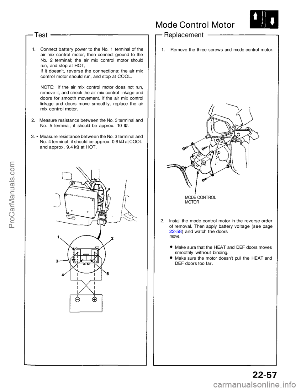
Test
1. Connect battery power to the No. 1 terminal of the air mix control motor, then connect ground to the
No. 2 terminal; the air mix control motor should
run, and stop at HOT,
If it doesn't, reverse the connections; the air mix
control motor should run, and stop at COOL.
NOTE: If the air mix control motor does not run,
remove it, and check the air mix control linkage and
doors for smooth movement. If the air mix control
linkage and doors move smoothly, replace the air
mix control motor.
2. Measure resistance between the No. 3 terminal and No. 5 terminal; it should be approx. 10 k. 3. • Measure resistance between the No. 3 terminal and
No. 4 terminal; if should be approx. 0.6 k
at COOL
and approx. 9.4 k at HOT.
Mode Control Motor
Replacement
1. Remove the three screws and mode control motor.
MODE CONTROL
MOTOR
2. Install the mode control motor in the reverse order of removal. Then apply battery voltage (see page
22-58) and watch the doors
move.
Make sura that the HEAT and DEF doors moves
smoothly without binding.
Make sure the motor doesn't pull the HEAT and
DEF doors too far.ProCarManuals.com
Page 703 of 1640
Blower Unit
Replacement
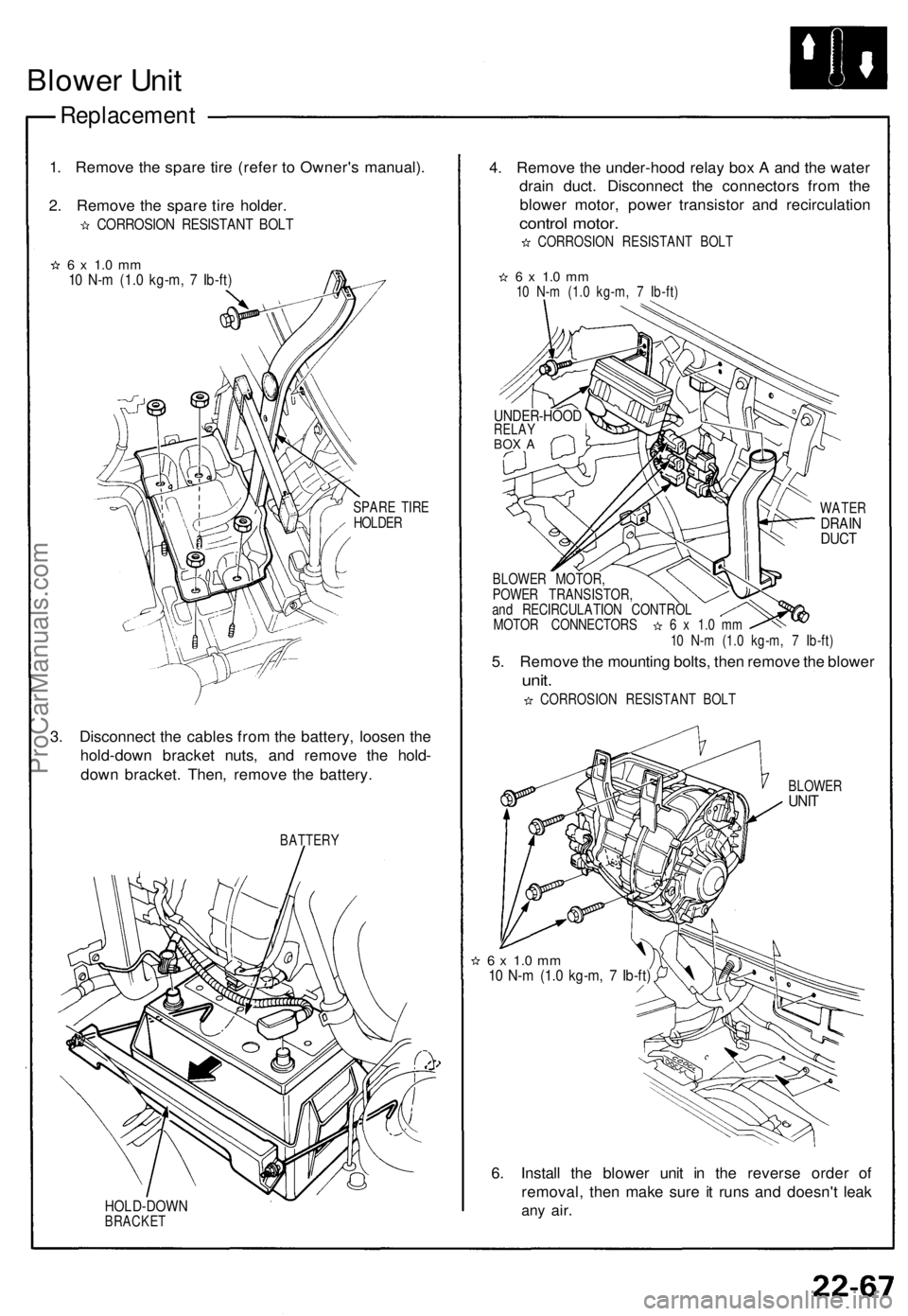
1. Remove the spare tire (refer to Owner's manual).
2. Remove the spare tire holder.
CORROSION RESISTANT BOLT
6 x 1.0 mm
10 N-m (1.0 kg-m, 7 Ib-ft)
SPARE TIRE
HOLDER
3. Disconnect the cables from the battery, loosen the
hold-down bracket nuts, and remove the hold-
down bracket. Then, remove the battery.
BATTERY
HOLD-DOWN
BRACKET
4. Remove the under-hood relay box A and the water
drain duct. Disconnect the connectors from the
blower motor, power transistor and recirculation
control motor.
CORROSION RESISTANT BOLT
6 x 1.0 mm
10 N-m (1.0 kg-m, 7 Ib-ft)
WATER
DRAIN
DUCT
BLOWER MOTOR,
POWER TRANSISTOR,
and RECIRCULATION CONTROL
MOTOR CONNECTORS 6 x 1.0 mm
10 N-m (1.0 kg-m, 7 Ib-ft)
5. Remove the mounting bolts, then remove the blower
unit.
CORROSION RESISTANT BOLT
BLOWER
UNIT
6 x 1.0 mm
10 N-m (1.0 kg-m, 7 Ib-ft)
6. Install the blower unit in the reverse order of
removal, then make sure it runs and doesn't leak
any
air.
UNDER-HOOD
RELAY
BOX AProCarManuals.com
Page 714 of 1640
Replacement
1. Disconnect the negative cable from the battery.
2. Remove the from bumper (see section 20).
3. Recover the refrigerant using a R-134a refrigerant Recover/Recycling/Charging System (see page
22-73).
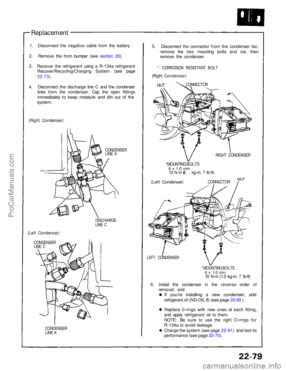
4. Disconnect the discharge line C and the condenser lines from the condenser. Cap the open fittings
immediately to keep moisture and dirt out of the
system.
(Right Condenser)
CONDENSER
LINE A
DISCHARGE
LINE C
(Left Condenser)
CONDENSER
LINE C
CONDENSER
LINE A
5. Disconnect the connector from the condenser fan,
remove the two mounting bolts and nut, then
remove the condenser.
*: CORROSION RESISTANT BOLT
(Right Condenser)
NUT
CONNECTOR
RIGHT CONDENSER
* MOUNTING BOLTS
6 x 1,0 mm
10 N·m (1.0 kg-m, 7 Ib-ft)
(Left Condenser)
CONNECTOR
NUT
LEFT CONDENSER * MOUNTING BOLTS
6 x 1.0 mm
10 N·m (1.0 kg-m. 7 Ib-ft)
6. Install the condenser in the reverse order of removal; and:
If you're installing a new condenser, add
refrigerant oil (ND-OIL 8) (see page 22-69 ).
Replace 0-rings with new ones at each fitting,
and apply refrigerant oil to them.
NOTE: Be sure to use the right O-rings for
R-134a to avoid leakage. Charge the system (see page 22-91) and test its
performance (see page 22-70).
ProCarManuals.com
Page 718 of 1640
Replacement
1. I f th e compresso r stil l works , ru n th e engin e a t idl e
for a fe w minute s wit h th e A/ C on , the n shu t th e
engin e of f an d disconnec t th e negativ e cabl e fro m
th e battery .
2 . Recove r th e refrigeran t usin g a R-134 a refrigeran t
Recovery/Recycling/Chargin g System . (se e pag e
22-73 ).
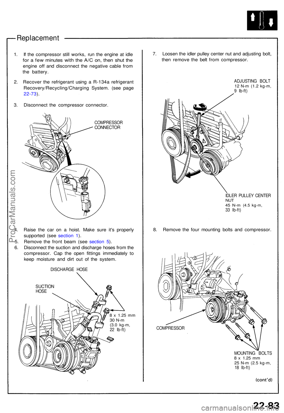
3 . Disconnec t th e compresso r connector .
COMPRESSO RCONNECTOR
4. Rais e th e ca r o n a hoist . Mak e sur e it' s properl y
supporte d (se e sectio n 1 ).
5 . Remov e th e fron t bea m (se e sectio n 5 ).
6 . Disconnec t th e suctio n an d discharg e hose s fro m th e
compressor . Ca p th e ope n fitting s immediatel y t o
kee p moistur e an d dir t ou t o f th e system .
DISCHARG E HOS E
SUCTIO NHOSE
8 x 1.2 5 mm30 N- m(3.0 kg-m ,22 Ib-ft )
7. Loose n th e idle r pulle y cente r nu t an d adjustin g bolt ,
the n remov e th e bel t fro m compressor .
ADJUSTING BOL T12 N- m (1. 2 kg-m ,9 Ib-ft )
IDLE R PULLE Y CENTE R
NUT45 N- m (4. 5 kg-m ,33 Ib-ft )
8. Remov e th e fou r mountin g bolt s an d compressor .
COMPRESSO R
MOUNTING BOLT S
8 x 1.2 5 mm25 N- m (2. 5 kg-m ,18 Ib-ft )
ProCarManuals.com
Page 751 of 1640
Starter Solenoid Test
1. Check the hold-in coil for continuity between the S
terminal and the armature housing (ground).
The coil is OK if there is continuity.
ARMATURE HOUSING
(GROUND)
PULL - IN COIL HOLD - IN COIL
2. Check the pull-in coil for continuity between the S
and M terminals.
The coil is OK if there is continuity.
Starter Replacement
1. Disconnect the battery negative cable.
2. Remove the engine wire harness from the harness
clip on the starter motor.
3. Disconnect the starter cable and the BLK/WHT
wire.
4. Remove the two bolts holding the starter, and
remove the starter.
UPPER MOUNTING BOLT
75 N-m (7.5 kg-m, 54 Ib-ft)
B-TERMINAL MOUNTING NUT
9 N-m (0.9 kg-m. 6.5 Ib-ft)
STARTER CABLE
LOWER MOUNTING BOLT
75 N-m (7.5 kg-m, 54 Ib-ft)
BLK/WHT WIREProCarManuals.com
Page 804 of 1640
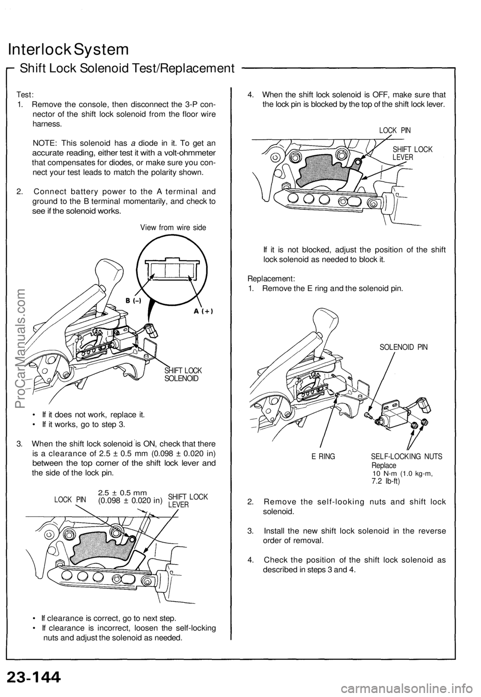
Interlock System
Shift Lock Solenoid Test/Replacement
Test:
1. Remove the console, then disconnect the 3-P con-
nector of the shift lock solenoid from the floor wire
harness.
NOTE: This solenoid has a diode in it. To get an
accurate reading, either test it with a volt-ohmmeter
that compensates for diodes, or make sure you con-
nect your test leads to match the polarity shown.
2. Connect battery power to the A terminal and
ground to the B terminal momentarily, and check to
see if the solenoid works.
View from wire side
SHIFT LOCK
SOLENOID
• If it does not work, replace it.
• If it works, go to step 3.
3. When the shift lock solenoid is ON, check that there
is a clearance of 2.5 ± 0.5 mm (0.098 ± 0.020 in)
between the top corner of the shift lock lever and
the side of the lock pin.
• If clearance is correct, go to next step.
• If clearance is incorrect, loosen the self-locking
nuts and adjust the solenoid as needed.
4. When the shift lock solenoid is OFF, make sure that
the lock pin is blocked by the top of the shift lock lever.
LOCK PIN
SHIFT LOCK
LEVER
If it is not blocked, adjust the position of the shift
lock solenoid as needed to block it.
Replacement:
1. Remove the E ring and the solenoid pin.
SOLENOID PIN
E RING SELF-LOCKING NUTS
Replace
10 N-m
(1.0 kg-m,
7.2 Ib-ft)
2. Remove the self-looking nuts and shift lock
solenoid.
3. Install the new shift lock solenoid in the reverse
order of removal.
4. Check the position of the shift lock solenoid as
described in steps 3 and 4.
LOCK PIN
2.5 ± 0.5 mm
(0.098 ± 0.020 in)
SHIFT LOCK
LEVERProCarManuals.com
Page 895 of 1640
Trunk Opener
Opener Switch Test
1. Remove the driver's door panel, then push the switch
out of the door panel as shown.
2. Check for continuity between the terminals.
• There should be continuity between the A and B
terminals when the switch is pushed.
• There should be no continuity when the switch
is released.
Solenoid Test/Replacement
1. Open the trunk lid, and remove the trunk side trim
panel.
2. Disconnect the 2-P connector from the solenoid
assembly, and test solenoid operation by connec-
ting battery power and ground to the A and B ter-
minals momentarily.
SOLENOID
ASSEMBLY
TRUNK LATCH
TRUNK OPENER
CABLE
BRACKET
BOLT
3. To remove the solenoid, remove the two bolts, then
disconnect the trunk opener cable from the
solenoid assembly.
OPENER CABLE
SOLENOID
ASSEMBLY
4. Install in the reverse order of removal.
BRACKET
View from
terminal side
DOOR
PANELProCarManuals.com