Page 945 of 1640
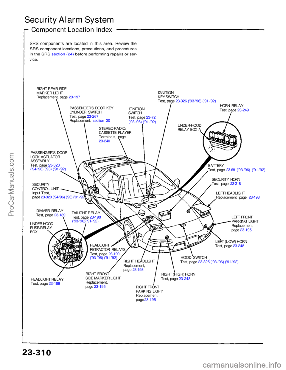
Security Alarm System
Component Location Index
SRS components are located in this area. Review the
SRS component locations, precautions, and procedures
i
n
the SRS section (24) before performing repairs or ser-
vice.
RIGHT REAR SIDE
MARKER LIGHT
Replacement, page 23-197 PASSENGER'S DOOR KEY
CYLINDER SWITCH
Test, page 23-267
Replacement, section 20
STEREO RADIO/
CASSETTE PLAYER
Terminals, page
23-240
IGNITION
SWITCH
Test, page 23-72
('93-'96) ('91-'92)
IGNITION
KEY SWITCH
Test, page 23-326 ('93-'96) ('91-'92)
UNDER-HOOD
RELAY BOX A
HORN RELAY
Test, page 23-249
BATTERY
Teat, page 23-68 ('93-'96) ('91-'92)
SECURITY HORN
Test, page 23-218 LEFT HEADLIGHT
Replacement page 23-193
LEFT FRONT
PARKING LIGHT
Replacement,
page 23-195
LEFT (LOW) HORN
Test, page 23-248
HOOD SWITCH
Test, page 23-325 ('93-'96) ('91-'92)
RIGHT (HIGH) HORN
Test, page 23-248
RIGHT FRONT
PARKING LIGHT
Replacement,
page 23-195
RIGHT HEADLIGHT
Replacement,
page 23-193
RIGHT FRONT
SIDE MARKER LIGHT
Replacement,
page 23-195 HEADLIGHT
RETRACTOR RELAYS
Test, page 23-190
('93-'96) ('91-'92)
HEADLIGHT RELAY
Test, page 23-189 TAILIGHT RELAY
Test, page 23-190
('93-'96)('91-'92)
UNDER-HOOD
FUSE/RELAY
BOX
DIMMER RELAY
Test, page 23-189
SECURITY
CONTROL UNIT
Input Test,
page 23-320 ('94-'96) ('93) ('91-'92)
PASSENGER'S DOOR
LOCK ACTUATOR
ASSEMBLY
Test, page 23-323
('94-'96) ('93) ('91-'92)ProCarManuals.com
Page 1118 of 1640
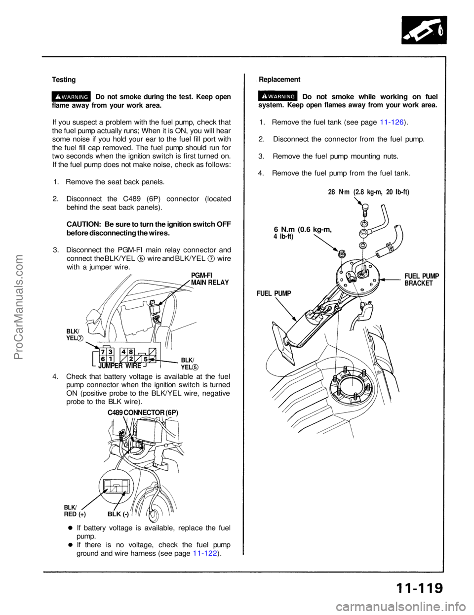
Testing
Do not smoke during the test. Keep open
If you suspect a problem with the fuel pump, check that
the fuel pump actually runs; When it is ON, you will hear some noise if you hold your ear to the fuel fill port with
the fuel fill cap removed. The fuel pump should run for
two seconds when the ignition switch is first turned on. If the fuel pump does not make noise, check as follows:
1. Remove the seat back panels.
2. Disconnect the C489 (6P) connector (located behind the seat back panels).
CAUTION: Be sure to turn the ignition switch OFF
before disconnecting the wires.
3. Disconnect the PGM-FI main relay connector and connect the BLK/YEL wire and BLK/YEL wire
with a jumper wire.
1. Remove the fuel tank (see page 11-126).
2. Disconnect the connector from the fuel pump.
3. Remove the fuel pump mounting nuts.
4. Remove the fuel pump from the fuel tank.
If battery voltage is available, replace the fuel
pump.
If there is no voltage, check the fuel pump
ground and wire harness (see page 11-122).
4. Check that battery voltage is available at the fuel
pump connector when the ignition switch is turned
ON (positive probe to the BLK/YEL wire, negative
probe to the BLK wire).
C489 CONNECTOR (6P)
BLK/
RED (+)
BLK (-)
JUMPER WIRE
flame away from your work area.
Replacement
Do not smoke while working on fuel
system. Keep open flames away from your work area.
28 N.
m (2.8 kg-m, 20 Ib-ft)
6 N.m
(0.6 kg-m,
4 Ib-ft)
FUEL PUMP
BRACKET
FUEL PUMP
PGM-FI
MAIN RELAY
BLK/
YEL
BLK/
YELProCarManuals.com
Page 1212 of 1640
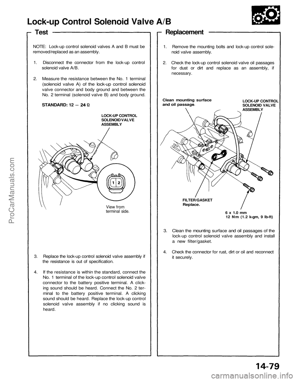
Lock-up Control Solenoid Valve A/B
Test
NOTE: Lock-up control solenoid valves A and B must be
removed/replaced as an assembly.
1. Disconnect the connector from the lock-up control solenoid valve A/B.
2. Measure the resistance between the No. 1 terminal
(solenoid valve A) of the lock-up control solenoid
valve connector and body ground and between the No. 2 terminal (solenoid valve B) and body ground.
View from
terminal side.
3. Replace the lock-up control solenoid valve assembly if the resistance is out of specification.
4. If the resistance is within the standard, connect the
No. 1 terminal of the lock-up control solenoid valve
connector to the battery positive terminal. A click-
ing sound should be heard. Connect the No. 2 ter-
minal to the battery positive terminal. A clicking
sound should be heard. Replace the lock-up controlsolenoid valve assembly if no clicking sound is
heard.
3. Clean the mounting surface and oil passages of the
lock-up control solenoid valve assembly and install
a new filter/gasket.
4. Check the connector for rust, dirt or oil and reconnect it securely.
6 x 1.0 mm
12 N.m (1.2 k-gm, 9 Ib-ft)
FILTER/GASKET
Replace.
LOCK-UP CONTROL
SOLENOID VALVE
ASSEMBLYClean mounting surface
and oil passages.
1. Remove the mounting bolts and lock-up control sole-
noid valve assembly.
2. Check the lock-up control solenoid valve oil passages for dust or dirt and replace as an assembly, if
necessary.
Replacement
STANDARD: 12
LOCK-UP CONTROL
SOLENOID VALVE
ASSEMBLYProCarManuals.com
Page 1213 of 1640
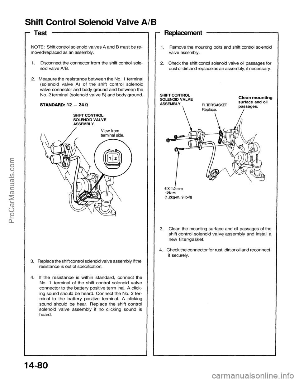
Shift Control Solenoid Valve A/B
Test
NOTE: Shift control solenoid valves A and B must be re-
moved/replaced as an assembly.
1. Disconnect the connector from the shift control sole-
noid valve A/B.
2. Measure the resistance between the No. 1 terminal (solenoid valve A) of the shift control solenoid
valve connector and body ground and between the No. 2 terminal (solenoid valve B) and body ground.
SHIFT CONTROL
SOLENOID VALVE
ASSEMBLY
View from
terminal side.
3. Replace the shift control solenoid valve assembly if the resistance is out of specification.
4. If the resistance is within standard, connect the No. 1 terminal of the shift control solenoid valve
connector to the battery positive term inal. A click-
ing sound should be heard. Connect the No. 2 ter-
minal to the battery positive terminal. A clicking
sound should be hear. Replace the shift control
solenoid valve assembly if no clicking sound is heard.
3. Clean the mounting surface and oil passages of the
shift control solenoid valve assembly and install a
new filter/gasket.
4. Check the connector for rust, dirt or oil and reconnect
it securely.
6 X 1.0 mm
12N .
m
(1.2kg-m, 9 Ib-ft)
FILTER/GASKET
Replace.
Clean mounting
surface and oil
passages.
SHIFT CONTROL
SOLENOID VALVE
ASSEMBLY
1. Remove the mounting bolts and shift control solenoid
valve assembly.
2. Check the shift contol solenoid valve oil passages for dust or dirt and replace as an assembly, if necessary.
ReplacementProCarManuals.com
Page 1214 of 1640
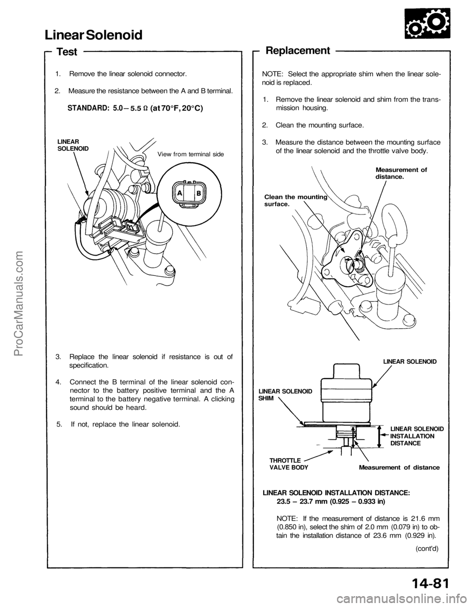
Linear Solenoid
Test
1. Remove the linear solenoid connector.
2. Measure the resistance between the A and B terminal.
LINEAR
SOLENOID
View from terminal side
3. Replace the linear solenoid if resistance is out of specification.
4. Connect the B terminal of the linear solenoid con- nector to the battery positive terminal and the A
terminal to the battery negative terminal. A clicking sound should be heard.
5. If not, replace the linear solenoid.
LINEAR SOLENOID INSTALLATION DISTANCE:
Measurement of distance
THROTTLE
VALVE BODY
LINEAR SOLENOID
SHIM
LINEAR SOLENOID
LINEAR SOLENOID
INSTALLATION
DISTANCE
Measurement of
distance.
Clean the mounting
surface.
NOTE: Select the appropriate shim when the linear sole-
noid is replaced.
1. Remove the linear solenoid and shim from the trans- mission housing.
2. Clean the mounting surface.
3. Measure the distance between the mounting surface of the linear solenoid and the throttle valve body.
Replacement
23.5 – 23.7 mm (0.925 – 0.933 in)
NOTE: If the measurement of distance is 21.6 mm (0.850 in), select the shim of 2.0 mm (0.079 in) to ob-
tain the installation distance of 23.6 mm (0.929 in).
(cont'd)
STANDARD: 5.0
5.5
(at 70°F, 20°C)ProCarManuals.com
Page 1593 of 1640
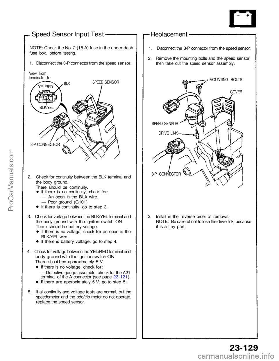
— Defective gauge assemble, check for the A21
Speed Sensor Input Test
NOTE
:
Check the No. 2 (15 A) fuse in the under-dash
fuse box, before testing.
1. Disconnect the 3-P connector from the speed sensor.
View from
terminal side
SPEED SENSOR
3-P CONNECTOR
2. Check for continuity between the BLK terminal and the body ground.
There should be continuity. If there is no continuity, check for:
— An open in the BLk wire.
— Poor ground (G101) If there is continuity, go to step 3.
3. Check for vortage between the BLK/YEL terminal and the body ground with the ignition switch ON.
There should be battery voltage. If there is no voltage, check for an open in the
BLK/YEL wire. If there is battery voltage, go to step 4.
4. Check for voltage between the YEL/RED terminal and
bod
y
ground with the ignition switch ON.
There should be approximately 5 V.
If there is no voltage, check for:
terminal of the A connector (see page 23-121). If there are approximately 5 V, go to step 5.
5. If all continuity and voltage tests are normal, but the speedometer and the odo/trip meter do not operate,
replace the speed sensor.
Replacement
1. Disconnect the 3-P connector from the speed sensor.
2. Remove the mounting bolts and the speed sensor,
then take out the speed sensor assembly.
DRIVE LINK
3-P CONNECTOR
3. Install in the reverse order of removal. NOTE: Be careful not to lose the drive link, because
it is a tiny part.
BLK
YEL/RED
BLK/YEL
SPEED SENSOR
COVER
MOUNTING BOLTSProCarManuals.com