Page 449 of 1640

System Description
Suspension Composition
Outline
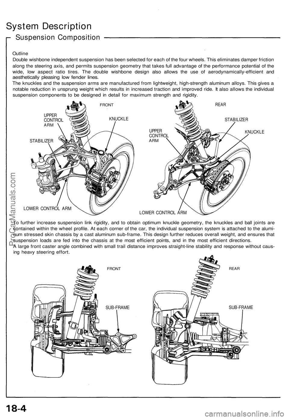
Double wishbone independent suspension has been selected for each of the four wheels. This eliminates damper friction
along the steering axis, and permits suspension geometry that takes full advantage of the performance potential of the
wide, low aspect ratio tires. The double wishbone design also allows the use of aerodynamically-efficient and
aesthetically pleasing low fender lines.
The knuckles and the suspension arms are manufactured from lightweight, high-strength aluminum alloys. This gives a
notable reduction in unsprung weight which results in increased traction and improved ride. It also allows the individual
suspension components to be designed in detail for maximum strength and rigidity.
FRONT
UPPER
CONTROL
ARM
KNUCKLE
STABILIZER
REAR
UPPER
CONTROL
ARM
STABILIZER
KNUCKLE
LOWER CONTROL ARM
LOWER CONTROL ARM
To further increase suspension link rigidity, and to obtain optimum knuckle geometry, the knuckles and ball joints are
contained within the wheel profile. At each corner of the car, the individual suspension system is attached to the alumi-
num stressed skin chassis by a cast aluminum sub-frame. This design further reduces overall weight, and ensures that
suspension loads are fed into the chassis at the most efficient points, and in the most efficient directions.
A large front caster angle combined with small trail distance improves straight-line stability and response without caus-
ing heavy steering effort.
FRONT
REAR
SUB-FRAME
SUB-FRAMEProCarManuals.com
Page 451 of 1640

Wheel Alignment
Height
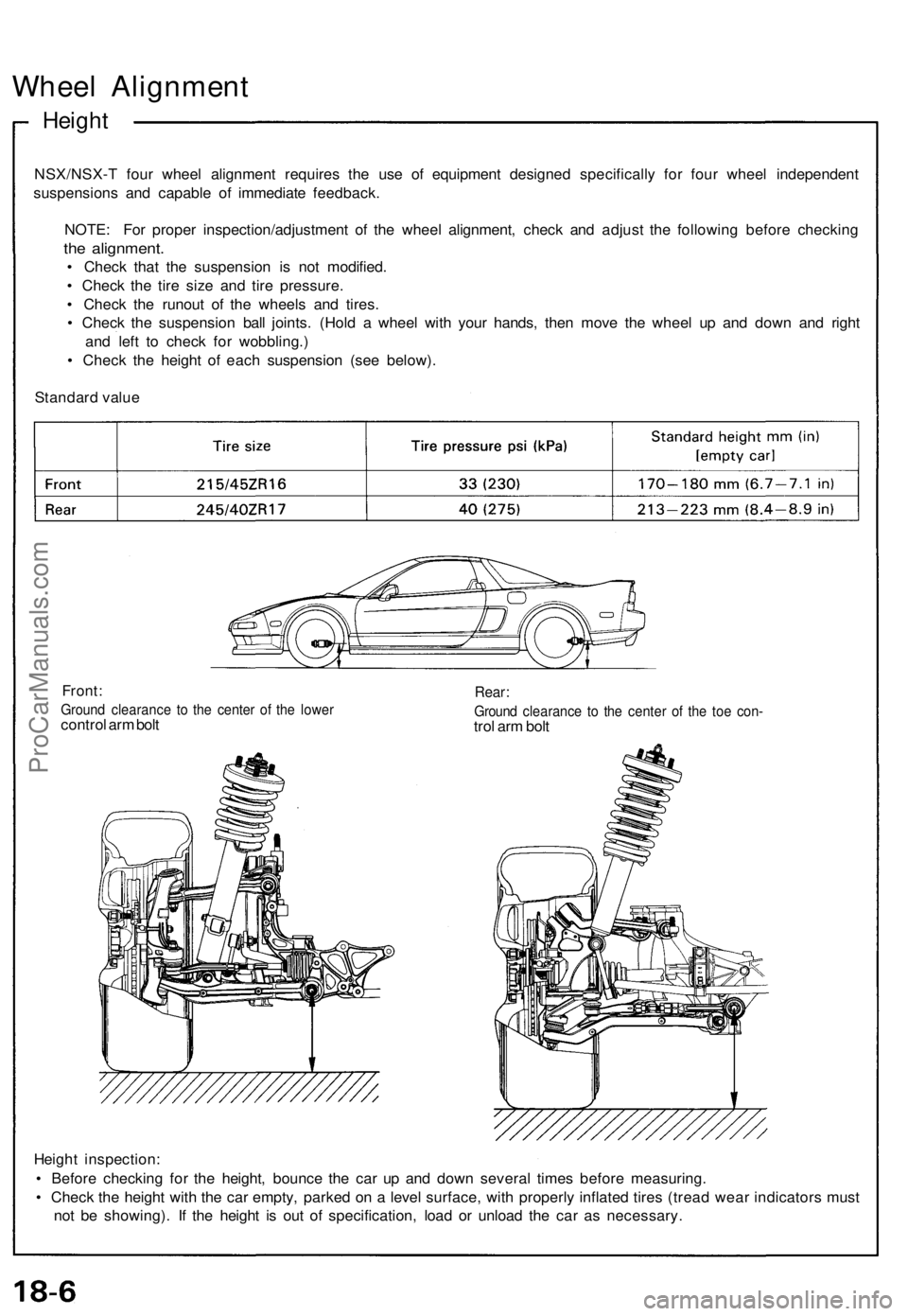
NSX/NSX-T four wheel alignment requires the use of equipment designed specifically for four wheel independent
suspensions and capable of immediate feedback.
NOTE: For proper inspection/adjustment of the wheel alignment, check and adjust the following before checking
the alignment.
• Check that the suspension is not modified.
• Check the tire size and tire pressure.
• Check the runout of the wheels and tires.
• Check the suspension ball joints. (Hold a wheel with your hands, then move the wheel up and down and right
and left to check for wobbling.)
• Check the height of each suspension (see below).
Standard value
Front:
Ground clearance to the center of the lower
control arm bolt
Rear:
Ground clearance to the center of the toe con-
trol arm bolt
Height inspection:
• Before checking for the height, bounce the car up and down several times before measuring.
• Check the height with the car empty, parked on a level surface, with properly inflated tires (tread wear indicators must
not be showing). If the height is out of specification, load or unload the car as necessary.ProCarManuals.com
Page 1362 of 1640

System Description
TCS Control unit
Acceleration Control:
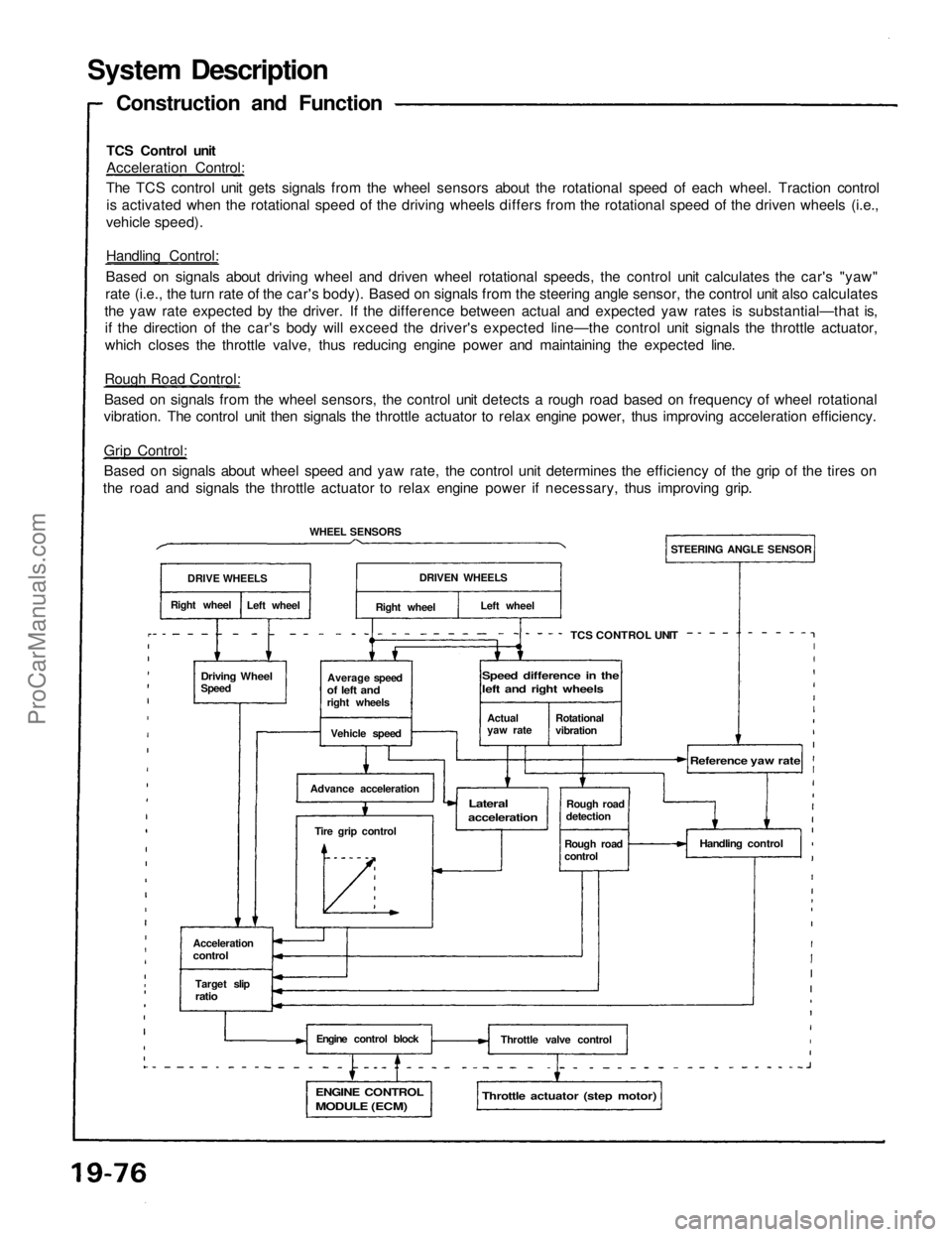
The TCS control unit gets signals from the wheel sensors about the rotational speed of each wheel. Traction control
is activated when the rotational speed of the driving wheels differs from the rotational speed of the driven wheels (i.e.,
vehicle speed).
Handling Control:
Based on signals about driving wheel and driven wheel rotational speeds, the control unit calculates the car's "yaw"
rate (i.e., the turn rate of the car's body). Based on signals from the steering angle sensor, the control unit also calculates
the yaw rate expected by the driver. If the difference between actual and expected yaw rates is substantial—that is,
if the direction of the car's body will exceed the driver's expected line—the control unit signals the throttle actuator,
which closes the throttle valve, thus reducing engine power and maintaining the expected line.
Rough Road Control:
Based on signals from the wheel sensors, the control unit detects a rough road based on frequency of wheel rotational
vibration. The control unit then signals the throttle actuator to relax engine power, thus improving acceleration efficiency.
Grip Control:
Based on signals about wheel speed and yaw rate, the control unit determines the efficiency of the grip of the tires on
the road and signals the throttle actuator to relax engine power if necessary, thus improving grip.
Construction and Function
DRIVE WHEELS
Right wheel
Left wheel
WHEEL SENSORS
Driving Wheel
Speed
Average speed
of left and
right wheels
Vehicle speed
Advance acceleration
Tire grip control
Acceleration
control
Target slip
ratio
Engine control block
ENGINE CONTROL
MODULE (ECM)
Throttle actuator (step motor)
Throttle valve control
Handling control
Rough road
detection
Rough road
control
Reference yaw rate
Lateral
acceleration
TCS CONTROL UNIT
STEERING ANGLE SENSOR
DRIVEN WHEELS
Right wheel
Left wheel
Actual
yaw rate
Rotational
vibration
Speed difference in the
left and right wheelsProCarManuals.com