1991 ACURA NSX wheel alignment
[x] Cancel search: wheel alignmentPage 80 of 1640
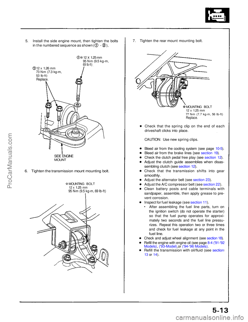
5. Install the side engine mount, then tighten the bolts
in the numbered sequence as shown ( - ),
12 x
1.26
mm
73 N·m
(7.3 kg-m,
53 Ib-ft)
Replace.
12 x
1.25
mm
95 N·m
(9.5 kg-m,
69 Ib-ft)
SIDE ENGINE
MOUNT
6. Tighten the transmission mount mounting bolt.
MOUNTING BOLT
12 x
1.25
mm
95 N·m (9.5 kg-m, 69 Ib-ft)
7. Tighten the rear mount mounting bolt.
MOUNTING BOLT
12 x
1.25
mm
77 N·m (7.7 kg-m, 56 Ib-ft)
Replace.
Check that the spring clip on the end of each
driveshaft clicks into place.
CAUTION: Use new spring clips.
Bleed air from the cooling system (see page 10-5).
Bleed air from the brake lines {see section 19).
Check the clutch pedal free play (see section 12).
Adjust the clutch guide assemblies when disas-
sembling clutch (see section 12).
Check that the transmission shifts into gear
smoothly.
Adjust the alternator belt (see section 23).
Adjust the A/C compressor belt (see section 22).
Clean battery posts and cable terminals with
sandpaper, assemble, then apply grease to pre-
vent corrosion.
Inspect for fuel leakage (see section 11). After assembling the fuel line parts, turn on
the ignition switch (do not operate the starter) so that the fuel pump operates for approxi-
mately two seconds and the fuel line pressu-
rizes. Repeat this operation two or three times
and check for fuel leakage at any point in the
fuel line.
Check and adjust wheel alignment (see section 18).
Refill the engine with engine oil (see page 8-4 ('91-'92
Models), ('93-Model),or ('94-'96 Models).
Refill the transmission with oil/fluid (see section
13 or
14).ProCarManuals.com
Page 424 of 1640
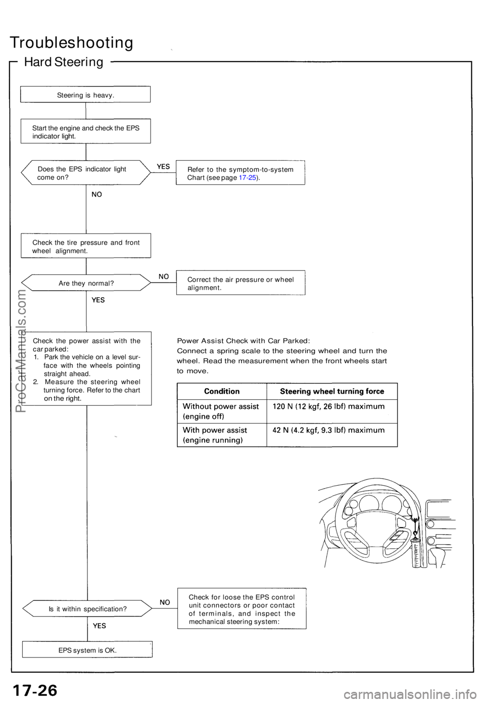
Troubleshooting
Hard Steerin g
Steering is heavy .
Star t th e engin e an d chec k th e EP S
indicato r light .
Does th e EP S indicato r ligh t
com e on ? Refe
r t o th e symptom-to-syste m
Char t (se e pag e 17-25 ).
Ar e the y normal ? Correc
t th e ai r pressur e o r whee l
alignment .
Chec k th e powe r assis t wit h th e
ca r parked :
1 . Par k th e vehicl e o n a leve l sur -
fac e wit h th e wheel s pointin g
straigh t ahead .
2 . Measur e th e steerin g whee l
turnin g force . Refe r t o th e char t
on th e right .
Powe r Assis t Chec k wit h Ca r Parked :
Connect a sprin g scal e t o th e steerin g whee l an d tur n th e
wheel . Rea d th e measuremen t whe n th e fron t wheel s star t
to move .
Is i t withi n specification ? Chec
k fo r loos e th e EP S contro l
uni t connector s o r poo r contac t
o f terminals , an d inspec t th e
mechanica l steerin g system :
EP S syste m is OK .
Chec
k th e tir e pressur e an d fron t
whee l alignment .
ProCarManuals.com
Page 429 of 1640
Installation
NOTE: Before installing the steering wheel, make sure
the front wheels are straight ahead.
CAUTION:
• Be sure to install the harness wires so that they are
not pinched or interfering with other car parts.
• Do not replace the original steering wheel with any
other design, since it will make it impossible to prop-
erly install the airbag. (Use only genuine Honda
replacement parts.)
• After reassembly, confirm that the wheels are still
straight ahead and that steering wheel spoke angle
is correct. If minor spoke angle adjustment is neces-
sary, adjust the tie-rods only. Do not remove and
reposition the steering wheel.
Confirm that the airbag assembly is securely
attached to the steering wheel; otherwise, severe per-
sonal injury could result during later airbag deploy-
ment.
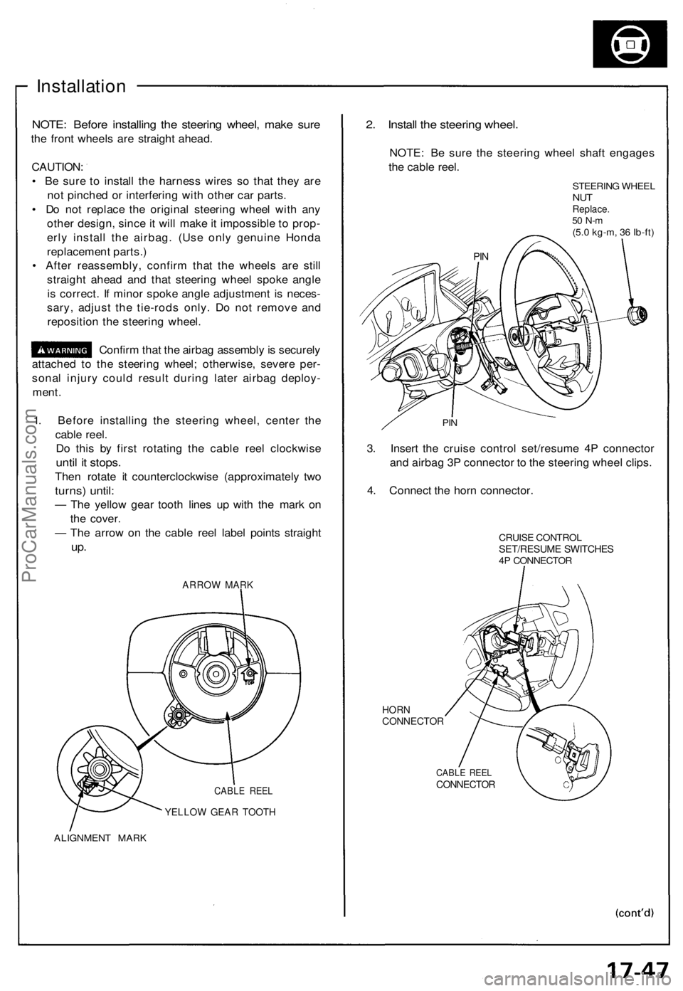
1. Before installing the steering wheel, center the
cable reel.
Do this by first rotating the cable reel clockwise
until it stops.
Then rotate it counterclockwise (approximately two
turns) until:
— The yellow gear tooth lines up with the mark on
the cover.
— The arrow on the cable reel label points straight
up.
ARROW MARK
CABLE REEL
YELLOW GEAR TOOTH
ALIGNMENT MARK
2. Install the steering wheel.
NOTE: Be sure the steering wheel shaft engages
the cable reel.
STEERING WHEEL
NUT
Replace.
50 N-m
(5.0 kg-m, 36 Ib-ft)
PIN
3. Insert the cruise control set/resume 4P connector
and airbag 3P connector to the steering wheel clips.
4. Connect the horn connector.
CRUISE CONTROL
SET/RESUME SWITCHES
4P CONNECTOR
HORN
CONNECTOR
CABLE REEL
CONNECTOR
PINProCarManuals.com
Page 430 of 1640
Steering Wheel
Installation
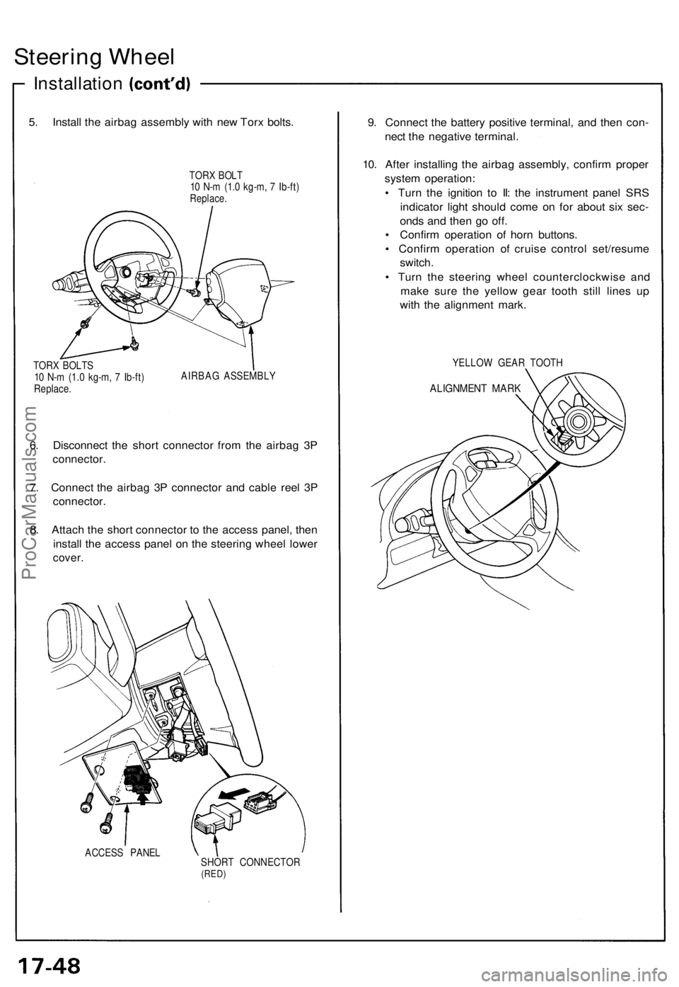
5. Install the airbag assembly with new Torx bolts.
TORX BOLT
10 N-m (1.0 kg-m, 7 Ib-ft)
Replace.
TORX BOLTS
10 N-m (1.0 kg-m, 7 Ib-ft)
Replace.
AIRBAG ASSEMBLY
6. Disconnect the short connector from the airbag 3P
connector.
7. Connect the airbag 3P connector and cable reel 3P
connector.
8. Attach the short connector to the access panel, then
install the access panel on the steering wheel lower
cover.
ACCESS PANEL
SHORT CONNECTOR
(RED)
9. Connect the battery positive terminal, and then con-
nect the negative terminal.
10. After installing the airbag assembly, confirm proper
system operation:
• Turn the ignition to II: the instrument panel SRS
indicator light should come on for about six sec-
onds and then go off.
• Confirm operation of horn buttons.
• Confirm operation of cruise control set/resume
switch.
• Turn the steering wheel counterclockwise and
make sure the yellow gear tooth still lines up
with the alignment mark.
YELLOW GEAR TOOTH
ALIGNMENT MARKProCarManuals.com
Page 451 of 1640
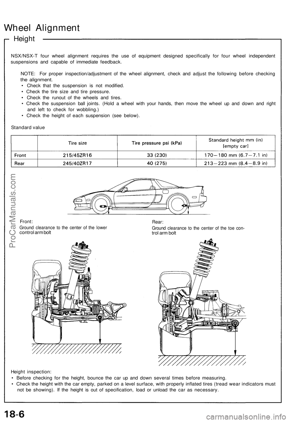
Wheel Alignment
Height
NSX/NSX-T four wheel alignment requires the use of equipment designed specifically for four wheel independent
suspensions and capable of immediate feedback.
NOTE: For proper inspection/adjustment of the wheel alignment, check and adjust the following before checking
the alignment.
• Check that the suspension is not modified.
• Check the tire size and tire pressure.
• Check the runout of the wheels and tires.
• Check the suspension ball joints. (Hold a wheel with your hands, then move the wheel up and down and right
and left to check for wobbling.)
• Check the height of each suspension (see below).
Standard value
Front:
Ground clearance to the center of the lower
control arm bolt
Rear:
Ground clearance to the center of the toe con-
trol arm bolt
Height inspection:
• Before checking for the height, bounce the car up and down several times before measuring.
• Check the height with the car empty, parked on a level surface, with properly inflated tires (tread wear indicators must
not be showing). If the height is out of specification, load or unload the car as necessary.ProCarManuals.com
Page 452 of 1640
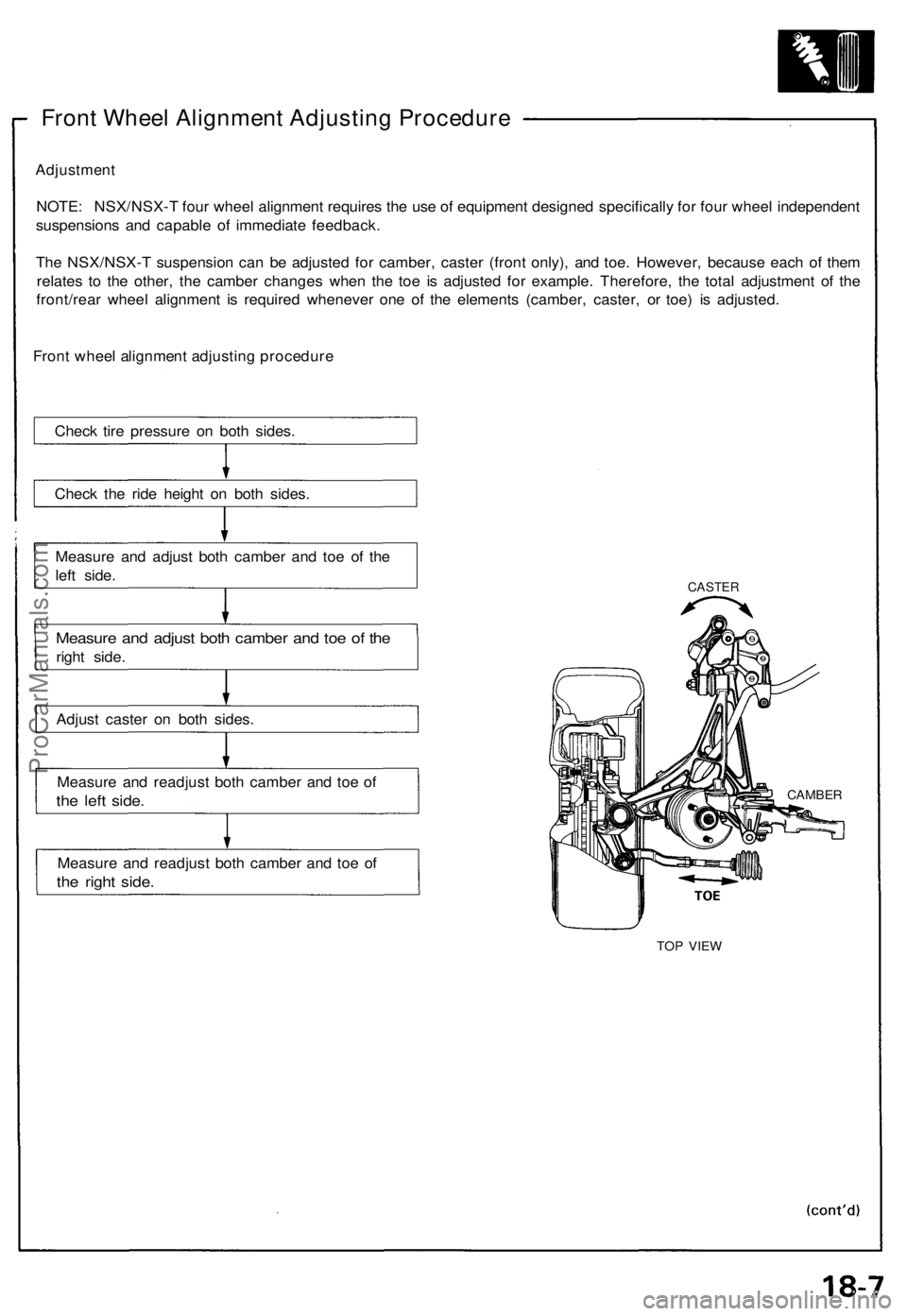
Front Wheel Alignment Adjusting Procedure
Adjustment
NOTE: NSX/NSX-T four wheel alignment requires the use of equipment designed specifically for four wheel independent
suspensions and capable of immediate feedback.
The NSX/NSX-T suspension can be adjusted for camber, caster (front only), and toe. However, because each of them
relates to the other, the camber changes when the toe is adjusted for example. Therefore, the total adjustment of the
front/rear wheel alignment is required whenever one of the elements (camber, caster, or toe) is adjusted.
Front wheel alignment adjusting procedure
Check tire pressure on both sides.
Check the ride height on both sides.
Measure and adjust both camber and toe of the
left side.
Measure and adjust both camber and toe of the
right side.
Adjust caster on both sides.
Measure and readjust both camber and toe of
the left side.
Measure and readjust both camber and toe of
the right side.
CASTER
TOP VIEW
CAMBERProCarManuals.com
Page 998 of 1640
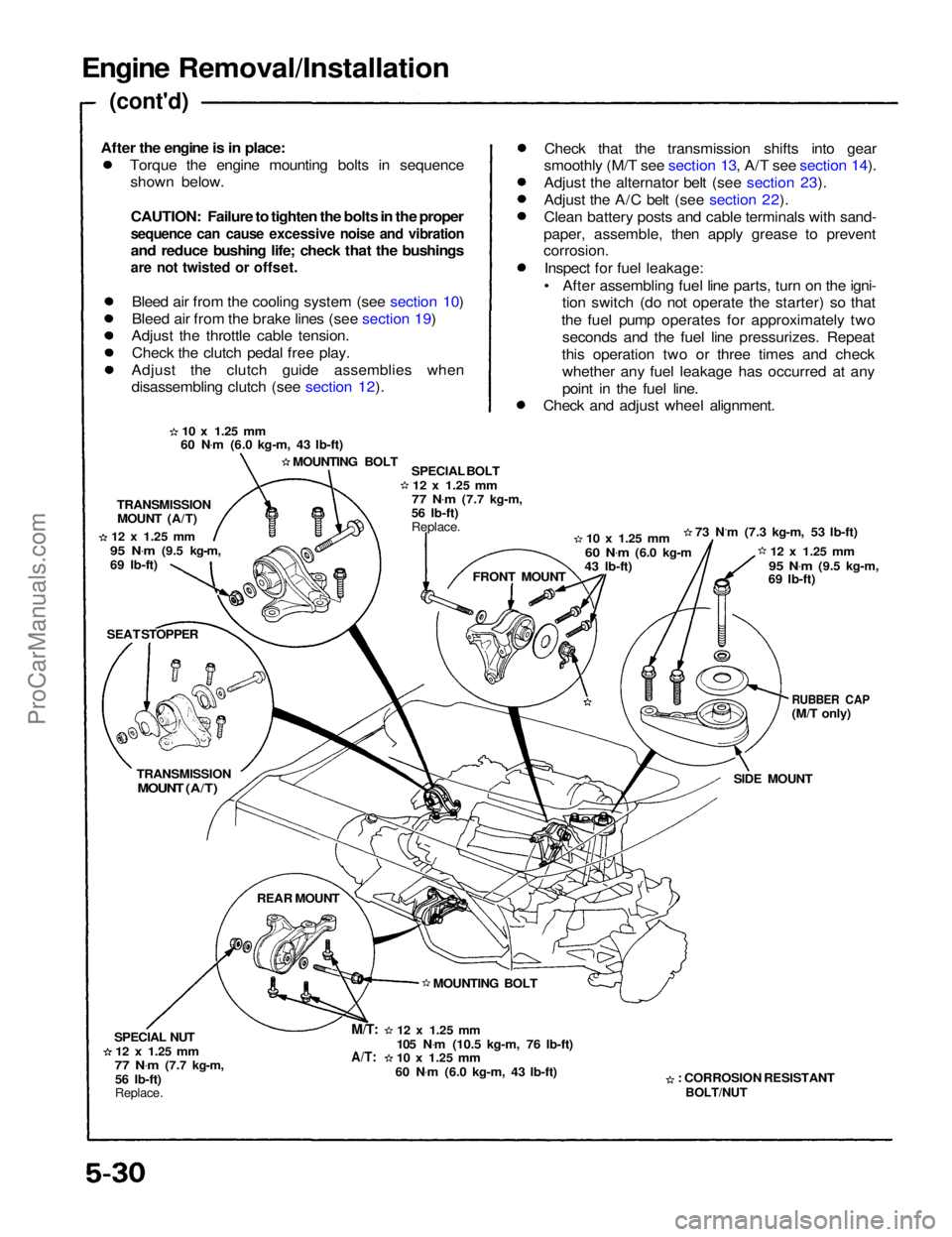
Engine Removal/Installation
(cont'd)
Torque the engine mounting bolts in sequenceshown below.
CAUTION: Failure to tighten the bolts in the proper
sequence can cause excessive noise and vibration
and reduce bushing life; check that the bushings
are not twisted or offset.
Bleed air from the cooling system (see section 10)
Bleed air from the brake lines (see section 19)
Adjust the throttle cable tension.
Check the clutch pedal free play.
Adjust the clutch guide assemblies when
disassembling clutch (see section 12). Check that the transmission shifts into gear
smoothly (M/T see section 13, A/T see section 14).
Adjust the alternator belt (see section 23).
Adjust the A/C belt (see section 22).
Clean battery posts and cable terminals with sand-
paper, assemble, then apply grease to prevent
corrosion.
Inspect for fuel leakage:
• After assembling fuel line parts, turn on the igni- tion switch (do not operate the starter) so that
the fuel pump operates for approximately two seconds and the fuel line pressurizes. Repeat
this operation two or three times and check whether any fuel leakage has occurred at any
point in the fuel line.
Check and adjust wheel alignment.
10 x
1.25
mm
60 N .
m (6.0 kg-m, 43 Ib-ft)
MOUNTING BOLT SPECIAL BOLT
12 x
1.25
mm
77 N .
m
(7.7 kg-m,
56 Ib-ft)
Replace.
10 x
1.25
mm
60 N .
m
(6.0 kg-m
43 Ib-ft) 73 N.m (7.3 kg-m, 53 Ib-ft)
12 x
1.25
mm
95 N .
m
(9.5 kg-m,
69 Ib-ft)
RUBBER CAP
(M/T only)
SIDE MOUNT
: CORROSION RESISTANT
BOLT/NUT
12 x
1.25
mm
105 N .
m (10.5 kg-m, 76 Ib-ft)
10 x
1.25
mm
60 N .
m (6.0 kg-m, 43 Ib-ft) MOUNTING BOLT FRONT MOUNT
TRANSMISSION
MOUNT (A/T)
12 x
1.25
mm
95 N .
m
(9.5 kg-m,
69 Ib-ft)
SEAT STOPPER
TRANSMISSION
MOUNT (A/T)
REAR MOUNT
SPECIAL NUT
12 x
1.25
mm
77 N .
m
(7.7 kg-m,
56 Ib-ft)
Replace.
M/T:
A/T:
After the engine is in place:ProCarManuals.com
Page 1148 of 1640
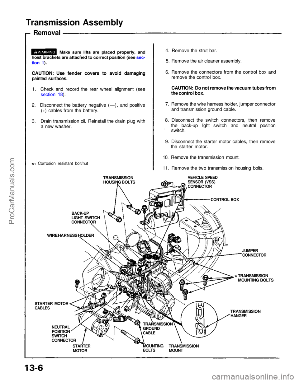
Transmission Assembly
Removal
CAUTION: Use fender covers to avoid damaging
painted surfaces.
1. Check and record the rear wheel alignment (see section 18).
2. Disconnect the battery negative (—), and positive (+) cables from the battery.
3. Drain transmission oil. Reinstall the drain plug with a new washer.
Corrosion resistant bolt/nut 4. Remove the strut bar.
5. Remove the air cleaner assembly.
6. Remove the connectors from the control box and remove the control box.
CAUTION: Do not remove the vacuum tubes from
the control box.
7. Remove the wire harness holder, jumper connector and transmission ground cable.
8. Disconnect the switch connectors, then remove the back-up light switch and neutral positionswitch.
9. Disconnect the starter motor cables, then remove the starter motor.
10. Remove the transmission mount.
11. Remove the two transmission housing bolts.
TRANSMISSION HOUSING BOLTS
BACK-UP
LIGHT SWITCH
CONNECTOR
WIRE HARNESS HOLDER
STARTER MOTOR
CABLES
NEUTRAL
POSITION
SWITCH
CONNECTOR
STARTER
MOTOR
TRANSMISSION
GROUND
CABLE
TRANSMISSION
MOUNT
MOUNTING
BOLTS
TRANSMISSION
HANGER
TRANSMISSION
MOUNTING BOLTS
JUMPER
CONNECTOR
VEHICLE SPEED
SENSOR (VSS)
CONNECTOR
CONTROL BOX
Make sure lifts are placed properly, and
hoist brackets are attached to correct position (see sec-
tion 1).ProCarManuals.com