Page 1303 of 1640

Steering Wheel
Installation
NOTE: Before installing the steering wheel, make sure
the front wheels are straight ahead.
CAUTION:
Be sure to install the harness wires so that they are
not pinched or interfering with other car parts.
Do not replace the original steering wheel with any
other design, since it will make it impossible to proper-
ly install the airbag. (Use only genuine HONDA
replacement parts.)
After reassembly, confirm that the wheels are still
straight ahead and that steering wheel spoke angle
is correct. If minor spoke angle adjustment is neces-
sary, adjust the tie-rods only. Do not remove and
reposition the steering wheel.
Confirm that the airbag assembly is secure-
ly attached to the steering wheel; otherwise, severe per-
sonal injury could result during later airbag deployment.
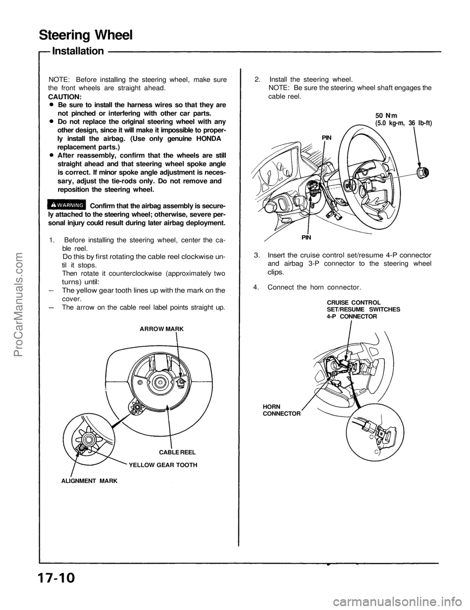
1. Before installing the steering wheel, center the ca-
ble reel.
Do this by first rotating the cable reel clockwise un-
til it stops.
Then rotate it counterclockwise (approximately two
turns) until:
ARROW MARK
CABLE REEL
YELLOW GEAR TOOTH
ALIGNMENT MARK
2. Install the steering wheel.
NOTE: Be sure the steering wheel shaft engages the
cable reel.
50 N.m
(5.0 kg-m, 36 Ib-ft)
PIN
PIN
3. Insert the cruise control set/resume 4-P connector
and airbag 3-P connector to the steering wheel
clips.
4. Connect the horn connector.
CRUISE CONTROL
SET/RESUME SWITCHES
4-P CONNECTOR
HORN
CONNECTOR
The yellow gear tooth lines up with the mark on the
cover.
The arrow on the cable reel label points straight up.ProCarManuals.com
Page 1304 of 1640
5.
Install
the
airbag assembly
with
new
TORX
®
bolts.
TORX ®
BOLT
10 N ·
m (1.0 kg-m, 7 Ib-ft)
Replace
TORX ®
BOLTS
10 N ·
m (1.0 kg-m, 7 Ib-ft)
Replace
AIRBAG ASSEMBLY
7. Disconnect the short connector from the airbag 3-P connector.
8. Connect the airbag 3-P connector and cable reel 3-P
connector.
9. Attach the short connector to the access panel, and install the access panel on the steering wheel
lower cover.
ACCESS PANEL SHORT CONNECTOR
(RED)
10. Connect the battery positive terminal and then con-
nect the negative terminal.
11. After installing the airbag assembly, confirm proper system operation:
Turn the ignition to II: the instrument panel SRSindicator light should come on for about 6
seconds and then go off.
Confirm operation of horn buttons.
Confirm operation of cruise control set/resume
switch.
Turn the steering wheel counterclockwise and
make sure the yellow gear tooth still lines up with
the alignment mark.
YELLOW GEAR TOOTH
ALIGNMENT MARKProCarManuals.com
Page 1311 of 1640
Component Location
Index
NOTE:
If an intact airbag assembly has been removed from a scrapped car or has been found defective or damaged during
transit, storage or service, it should be deployed (see section 23). Before removing the gearbox, remove the ignition key to lock the steering shaft from turning.
After installing the gearbox, check the wheel alignment and adjust if necessary.
STEERING WHEEL/AIRBAG ASSEMBLY
Removal, page 17-8
Disassembly, page 17-9
Installation, page 17-10
STEERING COLUMN
Removal, page 17-12
Inspection, page 17-14 Installation, page 17-15
STEERING GEARBOX
Removal/Installation, page 17-19 Disassembly, page 17-22
Inspection, page 17-21
Reassembly, page 17-25ProCarManuals.com
Page 1313 of 1640

Manual Steering
Gearbox Removal/Installation (Cont'd)
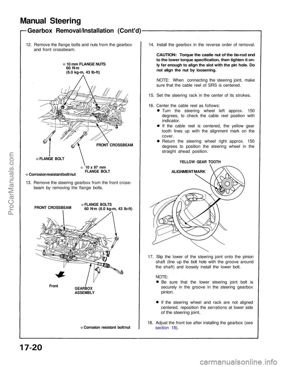
12. Remove the flange bolts and nuts from the gearbox and front crossbeam.
10 mm FLANGE NUTS
60 N ·
m
(6.0 kg-m, 43 Ib-ft)
FRONT CROSSBEAM
10 x 97 mm
FLANGE BOLT
FLANGE BOLT
Corrosion resistant bolt/nut
13. Remove the steering gearbox from the front cross- beam by removing the flange bolts.
FLANGE BOLTS
60 N.
m (6.0 kg-m, 43 Ib-ft)
FRONT CROSSBEAM
Front
GEARBOX
ASSEMBLY
Corrosion resistant bolt/nut
14. Install the gearbox in the reverse order of removal.
CAUTION: Torque the castle nut of the tie-rod end
to the lower torque specification, then tighten it on-
ly far enough to align the slot with the pin hole. Do
not align the nut by loosening.
NOTE: When connecting the steering joint, make
sure that the cable reel of SRS is centered.
15. Set the steering rack in the center of its strokes.
16. Center the cable reel as follows: Turn the steering wheel left approx. 150
degrees, to check the cable reel position with
indicator.
If the cable reel is centered, the yellow gear
tooth lines up with the alignment mark on the
cover.
Return the steering wheel right approx. 150
degrees to position the steering wheel in the
straight ahead position.
YELLOW GEAR TOOTH
ALIGNMENT MARK
17. Slip the lower of the steering joint onto the pinion shaft (line up the bolt hole with the groove around
the shaft) and loosely install the lower bolt.
NOTE:
Be sure that the lower steering joint bolt is
securely in the groove in the steering gearbox
pinion.
If the steering wheel and rack are not aligned
centered, reposition the serrations at lower side
of the steering joint.
18. Adjust the front toe after installing the gearbox (see section 18).ProCarManuals.com
Page 1322 of 1640
29. Install the new boot bands on the boot and bend both
sets of locking tabs.
30. Lightly tap on the doubled portions to reduce their
height.
NOTE: After assembling, slide the rack right and left
to be certain that the boots are not deformed or
twisted.
31. If the tie-rod ends were removed, install the tie- rods on the right and left rack ends and screw them
in until the threaded section is 11 mm (0.4 in) in
length.
BOOT BAND
11 mm
(0.4
in)
TIE-ROD END
LOCKNUT
Hand tighten.
32. Install the gearbox on the front crossbeam (see page 17-20).
33. Check the wheel alignment and adjust if necessary (see section 18).ProCarManuals.com
Page 1339 of 1640
Component Location
Index
NOTE:
EPS CONTROL UNITReplacement, page 17-74
POWER UNIT
Replacement, page 17-73
STEERING WHEEL/
AIRBAG ASSEMBLYRemoval, page 17-8
Disassembly, page 17-9
Installation, page 17-10
STEERING COLUMN
Removal, page 17-12
Inspection, page 17-14
Installation, page 17-15
STEERING GEARBOX Removal/Installation, page 17-64
Illustrated Index, page 17-68
Pinion Preload Inspection, page 17-69
Rack Guide Screw Adjustment, page 17-69
If an intact airbag assembly has been removed from a scrapped car or has been found defective or damaged during
transit, storage or service, it should be deployed (see section 23).
Before removing the gearbox, remove the ignition key to lock the steering shaft.
After installing the gearbox, check the wheel alignment and adjust if necessary.ProCarManuals.com
Page 1343 of 1640

21. Install the gearbox in the reverse order of removal.
NOTE: When connecting the steering joint, make
sure that the cable reel of airbag system is
centered.
22. Set the steering rack in the center of its stroke.
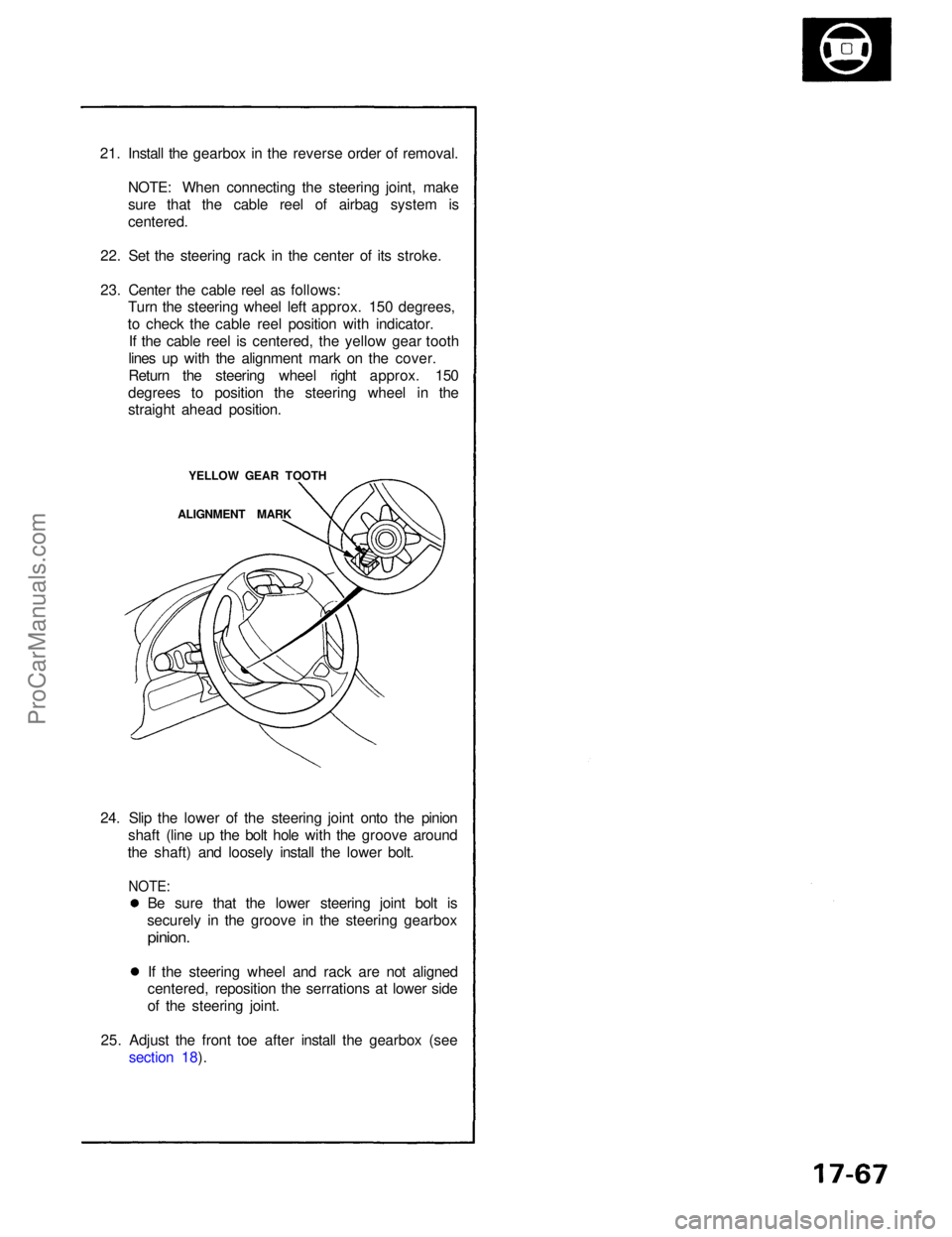
23. Center the cable reel as follows: Turn the steering wheel left approx. 150 degrees,
to check the cable reel position with indicator. If the cable reel is centered, the yellow gear tooth
lines up with the alignment mark on the cover.
Return the steering wheel right approx. 150
degrees to position the steering wheel in the
straight ahead position.
YELLOW GEAR TOOTH
ALIGNMENT MARK
24. Slip the lower of the steering joint onto the pinion shaft (line up the bolt hole with the groove around
the shaft) and loosely install the lower bolt.
NOTE:
Be sure that the lower steering joint bolt is
securely in the groove in the steering gearbox
pinion.
If the steering wheel and rack are not aligned
centered, reposition the serrations at lower side
of the steering joint.
25. Adjust the front toe after install the gearbox (see section 18).ProCarManuals.com
Page 1347 of 1640

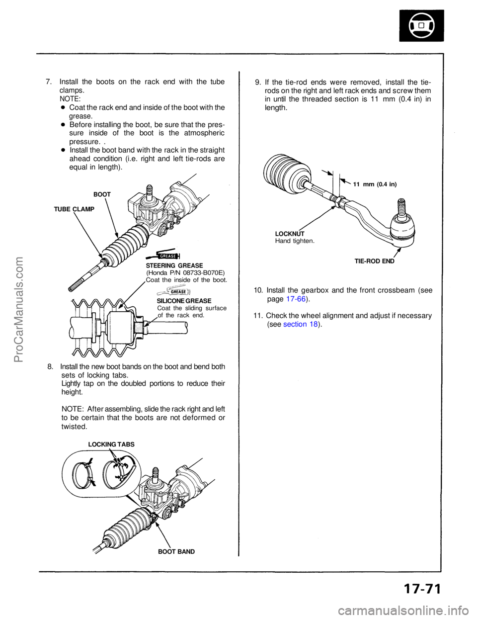
7. Install the boots on the rack end with the tube
clamps.
NOTE:
BOOT
TUBE CLAMP
STEERING GREASE
(Honda P/N 08733-B070E)
Coat the inside of the boot.
SILICONE GREASECoat the sliding surface of the rack end.
8. Install the new boot bands on the boot and bend both sets of locking tabs.
Lightly tap on the doubled portions to reduce their
height.
NOTE: After assembling, slide the rack right and left
to be certain that the boots are not deformed or
twisted. 9. If the tie-rod ends were removed, install the tie-
rods on the right and left rack ends and screw them
in until the threaded section is 11 mm (0.4 in) in
length.
10. Install the gearbox and the front crossbeam (see page 17-66).
11. Check the wheel alignment and adjust if necessary (see section 18).
BOOT BAND
LOCKING TABS
11 mm
(0.4
in)
LOCKNUT
Hand tighten.
TIE-ROD END
Coat the rack end and inside of the boot with the
grease.
Before installing the boot, be sure that the pres-
sure inside of the boot is the atmospheric
pressure. .
Install the boot band with the rack in the straight
ahead condition (i.e. right and left tie-rods are
equal in length).ProCarManuals.com