1991 ACURA NSX weight
[x] Cancel search: weightPage 11 of 1640
Towing
If th e ca r need s t o b e towed , cal l a professiona l towin g
service . Neve r to w th e ca r behin d anothe r ca r wit h jus t
a rop e o r chain . I t i s ver y dangerous .
Ther e ar e thre e widel y use d method s o f towin g a car :
Flat-be d Equipmen t — Th e operato r load s th e ca r o n th e
bac k o f a truck . Thi s i s th e onl y recommende d wa y o f
towin g th e NS X & NSX-T .
Whee l Lif t Equipment— The to w truc k drive r use s tw o
pivotin g arm s whic h g o unde r th e tire s (fron t o r rear ) an d
lif t the m of f th e ground . Th e othe r tw o wheel s remai n
o n th e ground . Thi s towin g metho d i s no t recommend -
ed . Becaus e o f th e NS X & NSX-T' s lo w groun d clearance ,
th e bod y ca n b e damage d goin g ove r larg e bump s o r u p
inclines .
Sling-typ e Equipment— The tow truc k use s meta l chain s
wit h hook s o n th e ends . Thes e hook s g o aroun d part s
of th e fram e or suspensio n and th e cable s lift tha t end
of th e ca r of f th e ground . Damag e t o th e car' s suspen -
sio n an d bod y i s almos t certai n if thi s metho d o f towin g
i s attempted .
I f th e NS X & NSX- T canno t b e towe d b y flat-bed , i t
shoul d b e towe d wit h th e rea r wheel s of f th e ground .
If , du e t o damage , th e ca r mus t b e towe d wit h th e rea r
wheel s o n th e ground , d o th e following :
Manual Transmissio n
• Releas e th e parkin g brak e
• Shif t th e transmissio n t o Neutra l
Automati c Transmissio n
• Releas e th e parkin g brak e
• Star t th e engin e
• Shif t t o position , the n t o positio n
• Tur n of f th e engin e
NOTICE :
• Imprope r towin g preparatio n wil l damag e th e trans -
mission . Follo w th e abov e procedur e exactly . Th e ca r
mus t b e towe d o n a fla t be d if th e engin e wil l no t star t
o r th e transmissio n wil l no t shift .
• I t i s bes t t o to w th e ca r n o farthe r tha n 5 0 mile s (8 0
km) , an d kee p th e spee d belo w 3 5 mp h (5 5 km/h) .
• Tryin g t o lif t o r to w th e ca r b y th e bumper s wil l caus e
seriou s damage . Th e bumper s ar e no t designe d to sup -
por t th e car' s weight .
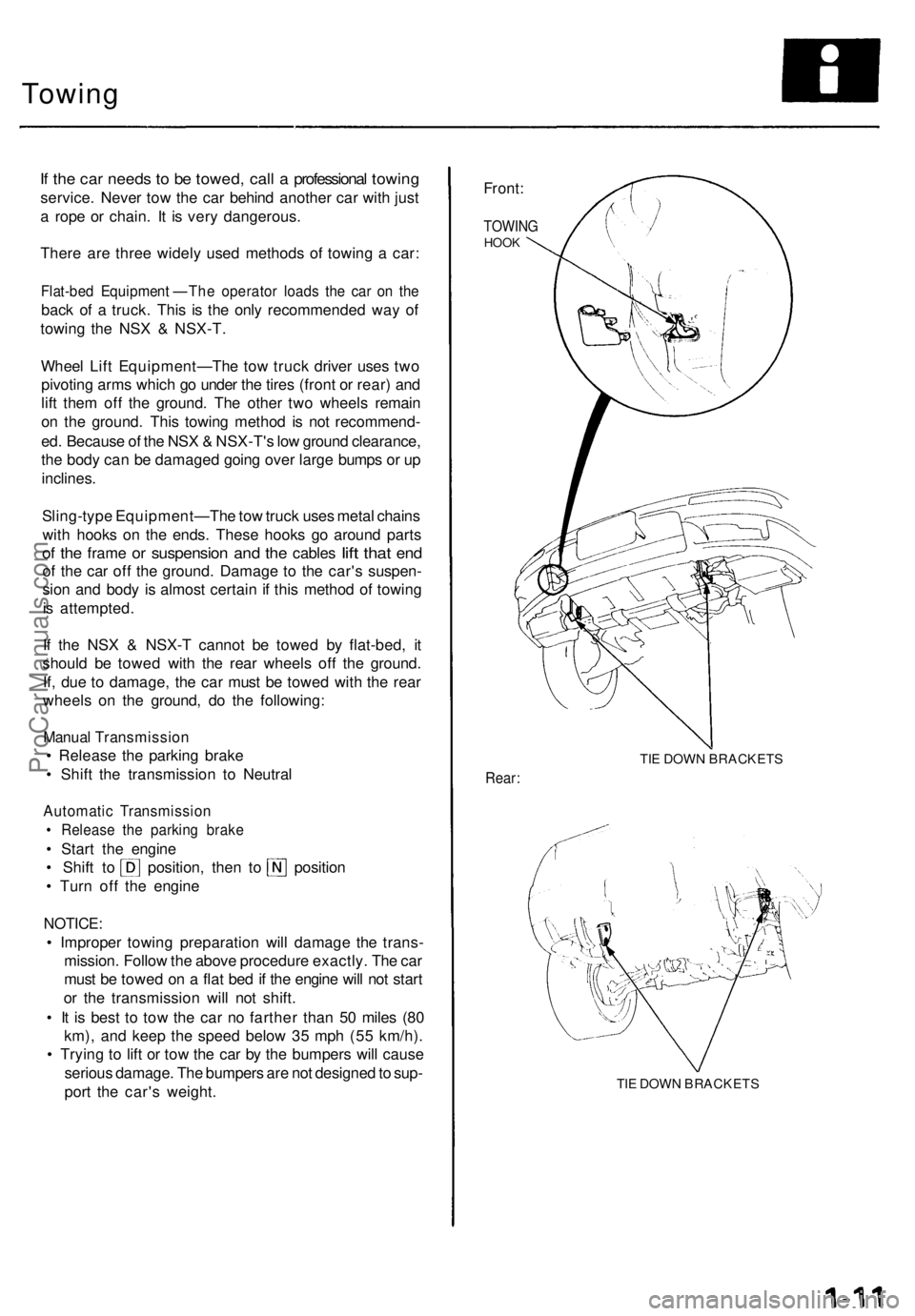
Front:
TOWIN GHOOK
TIE DOW N BRACKET S
Rear:
TIE DOW N BRACKET S
ProCarManuals.com
Page 44 of 1640
Towing
If th e ca r need s t o b e towed , cal l a professiona l towin g
service . Neve r to w th e ca r behin d anothe r ca r wit h jus t
a rop e o r chain . I t i s ver y dangerous .
Ther e ar e thre e widel y use d method s o f towin g a car :
Flat-be d Equipment—Th e operato r load s th e ca r o n th e
bac k o f a truck . This is th e onl y recommende d wa y o f
towin g th e NS X & NSX-T .
Whee l Lif t Equipment—Th e to w truc k drive r use s tw o
pivotin g arm s whic h g o unde r th e tire s (fron t o r rear ) an d
lif t the m of f th e ground . Th e othe r tw o wheel s remai n
o n th e ground . Thi s towin g metho d i s no t recommend -
ed . Becaus e o f th e NS X & NSX-T' s lo w groun d clearance ,
th e bod y ca n b e damage d goin g ove r larg e bump s o r u p
inclines .
Sling-typ e Equipment—Th e to w truc k use s meta l chain s
wit h hooks on th e ends . Thes e hook s g o aroun d part s
o f th e fram e o r suspensio n an d th e cable s lif t tha t en d
o f th e ca r of f th e ground . Damag e t o th e car' s suspen -
sio n an d bod y i s almos t certai n if thi s metho d o f towin g
i s attempted .
I f th e NS X & NSX- T canno t b e towe d b y flat-bed , i t
shoul d b e towe d wit h th e rea r wheel s of f th e ground .
If , du e t o damage , th e ca r mus t b e towe d wit h th e rea r
wheel s o n th e ground , d o th e following :
Manual Transmissio n
Release th e parkin g brak e
Shift th e transmissio n t o Neutra l
Automati c Transmissio n
Releas e th e parkin g brak e
Star t th e engin e
Shift t o position , the n t o positio n
Tur n of f th e engin e
NOTICE :
Improper towin g preparatio n wil l damag e th e trans -
mission . Follo w th e abov e procedur e exactly . Th e ca r
mus t b e towe d o n a fla t be d if th e engin e wil l no t star t
or th e transmissio n wil l no t shift .
It i s bes t t o to w th e ca r n o farthe r tha n 5 0 mile s (8 0
km) , an d kee p th e spee d belo w 3 5 mp h (5 5 km/h) .
Tryin g t o lif t o r to w th e ca r b y th e bumper s wil l caus e
seriou s damage . Th e bumper s ar e no t designe d to sup -
por t th e car' s weight .
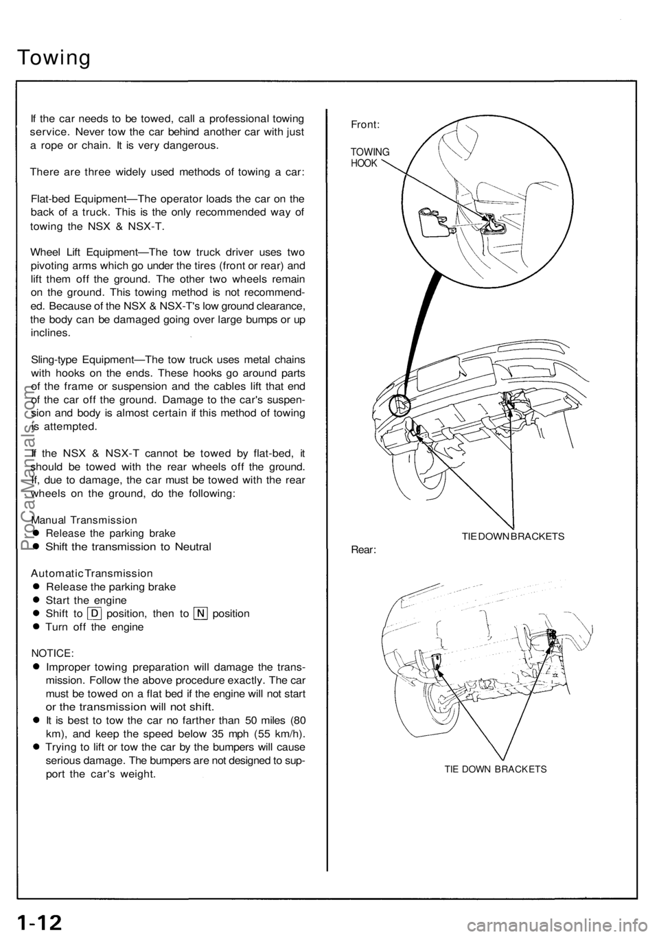
Front:
TOWIN GHOOK
TIE DOW N BRACKET S
Rear:
TIE DOW N BRACKET S
ProCarManuals.com
Page 131 of 1640
Main Bearing s
Clearanc e
1. T o chec k mai n bearing-to-journa l oi l clearance ,
remov e th e mai n cap s an d bearin g halves .
2 . Clea n eac h mai n journa l an d bearin g hal f wit h a
clea n sho p towel.
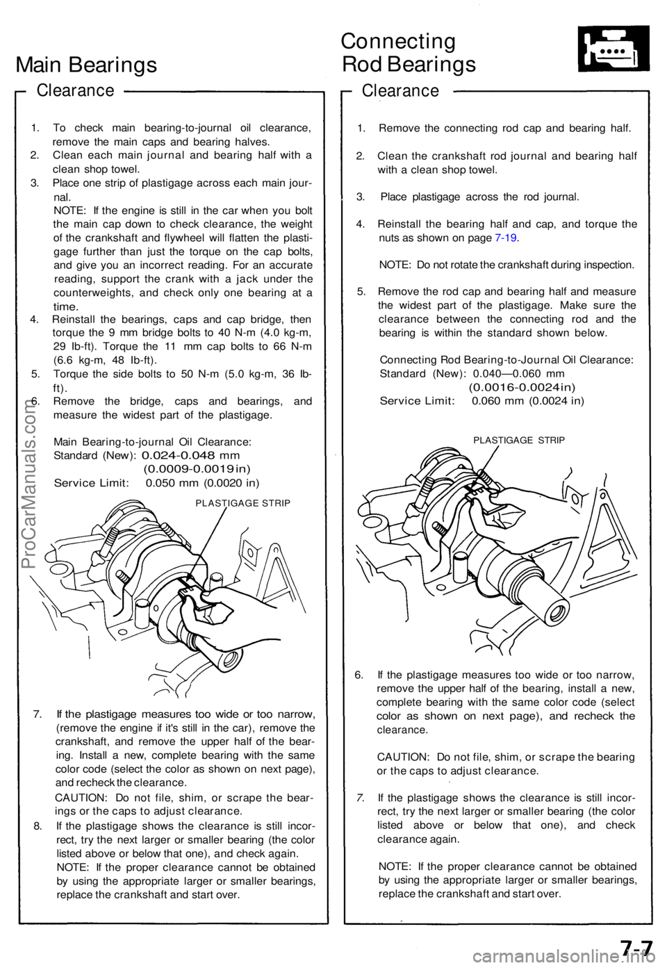
3 . Plac e on e stri p o f plastigag e acros s eac h mai n jour -
nal.
NOTE : I f th e engine is stil l i n th e ca r whe n yo u bol t
th e mai n ca p dow n t o chec k clearance , th e weigh t
o f th e crankshaf t an d flywhee l wil l flatte n th e plasti -
gag e furthe r tha n jus t th e torqu e o n th e ca p bolts ,
an d giv e yo u a n incorrec t reading . Fo r a n accurat e
reading , suppor t th e cran k wit h a jac k unde r th e
counterweights , an d chec k onl y on e bearin g a t a
time .
4. Reinstal l th e bearings , cap s an d ca p bridge , the n
torqu e th e 9 m m bridg e bolt s t o 4 0 N- m (4. 0 kg-m ,
2 9 Ib-ft) . Torqu e th e 1 1 m m ca p bolt s t o 6 6 N- m
(6. 6 kg-m , 4 8 Ib-ft) .
5 . Torqu e th e sid e bolt s t o 5 0 N- m (5. 0 kg-m , 3 6 Ib -
ft).
6. Remov e th e bridge , cap s an d bearings , an d
measur e th e wides t par t o f th e plastigage .
Mai n Bearing-to-journa l Oi l Clearance :
Standar d
(New): 0.024-0.04 8 mm
(0.0009-0.001 9 in )
Servic e Limit : 0.05 0 m m (0.002 0 in )
PLASTIGAG E STRI P
7. I f th e plastigag e measure s to o wid e o r to o narrow ,
(remove th e engine if it' s stil l i n th e car) , remov e th e
crankshaft , an d remov e th e uppe r hal f o f th e bear -
ing . Instal l a new , complet e bearin g wit h th e sam e
colo r cod e (selec t th e colo r a s show n o n nex t page) ,
an d rechec k th e clearance .
CAUTION : D o no t file , shim , o r scrap e th e bear -
ing s o r th e cap s t o adjus t clearance .
8 . I f th e plastigag e show s th e clearanc e i s stil l incor -
rect , tr y th e nex t large r o r smalle r bearin g (th e colo r
liste d abov e o r belo w tha t one) , an d chec k again .
NOTE : I f th e prope r clearanc e canno t b e obtaine d
b y usin g th e appropriat e large r o r smalle r bearings ,
replac e th e crankshaf t an d star t over .
Connectin g
Rod Bearing s
Clearanc e
1. Remov e th e connectin g ro d ca p an d bearin g half .
2 . Clea n th e crankshaf t ro d journa l an d bearin g hal f
wit h a clea n sho p towel .
3 . Plac e plastigag e acros s th e ro d journal .
4 . Reinstal l th e bearin g hal f an d cap , an d torqu e th e
nut s a s show n o n pag e 7-19 .
NOTE : D o no t rotat e th e crankshaft during inspection .
5 . Remov e th e ro d ca p an d bearin g hal f an d measur e
th e wides t par t o f th e plastigage . Mak e sur e th e
clearanc e betwee n th e connectin g ro d an d th e
bearin g i s withi n th e standar d show n below .
Connectin g Ro d Bearing-to-Journa l Oi l Clearance :
Standar d (New) : 0.040—0.06 0 m m
(0.0016-0.002 4 in )
Servic e Limit : 0.06 0 m m (0.002 4 in )
PLASTIGAG E STRI P
6. I f th e plastigag e measure s to o wid e o r to o narrow ,
remov e th e uppe r hal f of the bearing , instal l a new ,
complet e bearin g wit h th e sam e colo r cod e (selec t
color a s show n o n nex t page) , an d rechec k th e
clearance .
CAUTION: D o no t file , shim , o r scrap e th e bearin g
o r th e cap s t o adjus t clearance .
7. I f th e plastigag e show s th e clearanc e i s stil l incor -
rect , tr y th e nex t large r o r smalle r bearin g (th e colo r
liste d abov e o r belo w tha t one) , an d chec k
clearanc e again .
NOTE : I f th e prope r clearanc e canno t b e obtaine d
b y usin g th e appropriat e large r o r smalle r bearings ,
replac e th e crankshaf t an d star t over .
ProCarManuals.com
Page 307 of 1640
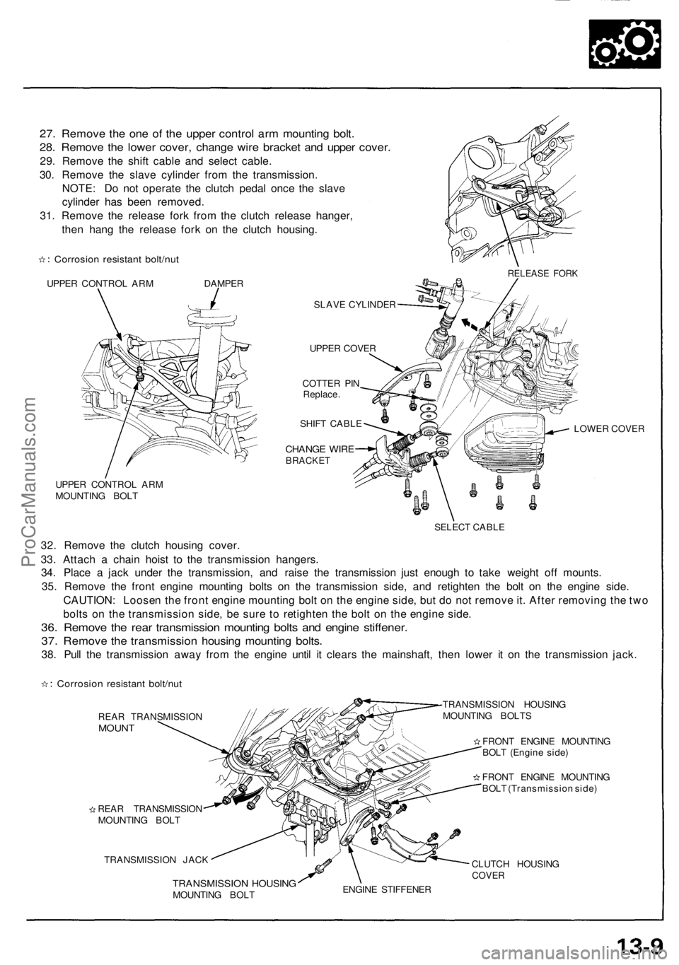
27. Remove the one of the upper control arm mounting bolt.
28. Remove the lower cover, change wire bracket and upper cover.
29. Remove the shift cable and select cable.
30. Remove the slave cylinder from the transmission.
NOTE: Do not operate the clutch pedal once the slave
cylinder has been removed.
31. Remove the release fork from the clutch release hanger,
then hang the release fork on the clutch housing.
Corrosion resistant bolt/nut
UPPER CONTROL ARM DAMPER
SLAVE CYLINDER
UPPER COVER
COTTER PIN
Replace.
SHIFT CABLE
CHANGE WIRE
BRACKET
UPPER CONTROL ARM
MOUNTING BOLT
LOWER COVER
SELECT CABLE
32. Remove the clutch housing cover.
33. Attach a chain hoist to the transmission hangers.
34. Place a jack under the transmission, and raise the transmission just enough to take weight off mounts.
35. Remove the front engine mounting bolts on the transmission side, and retighten the bolt on the engine side.
CAUTION: Loosen the front engine mounting bolt on the engine side, but do not remove it. After removing the two
bolts on the transmission side, be sure to retighten the bolt on the engine side.
36. Remove the rear transmission mounting bolts and engine stiffener.
37. Remove the transmission housing mounting bolts.
38. Pull the transmission away from the engine until it clears the mainshaft, then lower it on the transmission jack.
Corrosion resistant bolt/nut
REAR TRANSMISSION
MOUNT
REAR TRANSMISSION
MOUNTING BOLT
TRANSMISSION JACK
TRANSMISSION HOUSING
MOUNTING BOLTS
FRONT ENGINE MOUNTING
BOLT (Engine side)
FRONT ENGINE MOUNTING
BOLT (Transmission side)
TRANSMISSION HOUSING
MOUNTING BOLT
CLUTCH HOUSING
COVER
ENGINE STIFFENER
RELEASE FORKProCarManuals.com
Page 407 of 1640
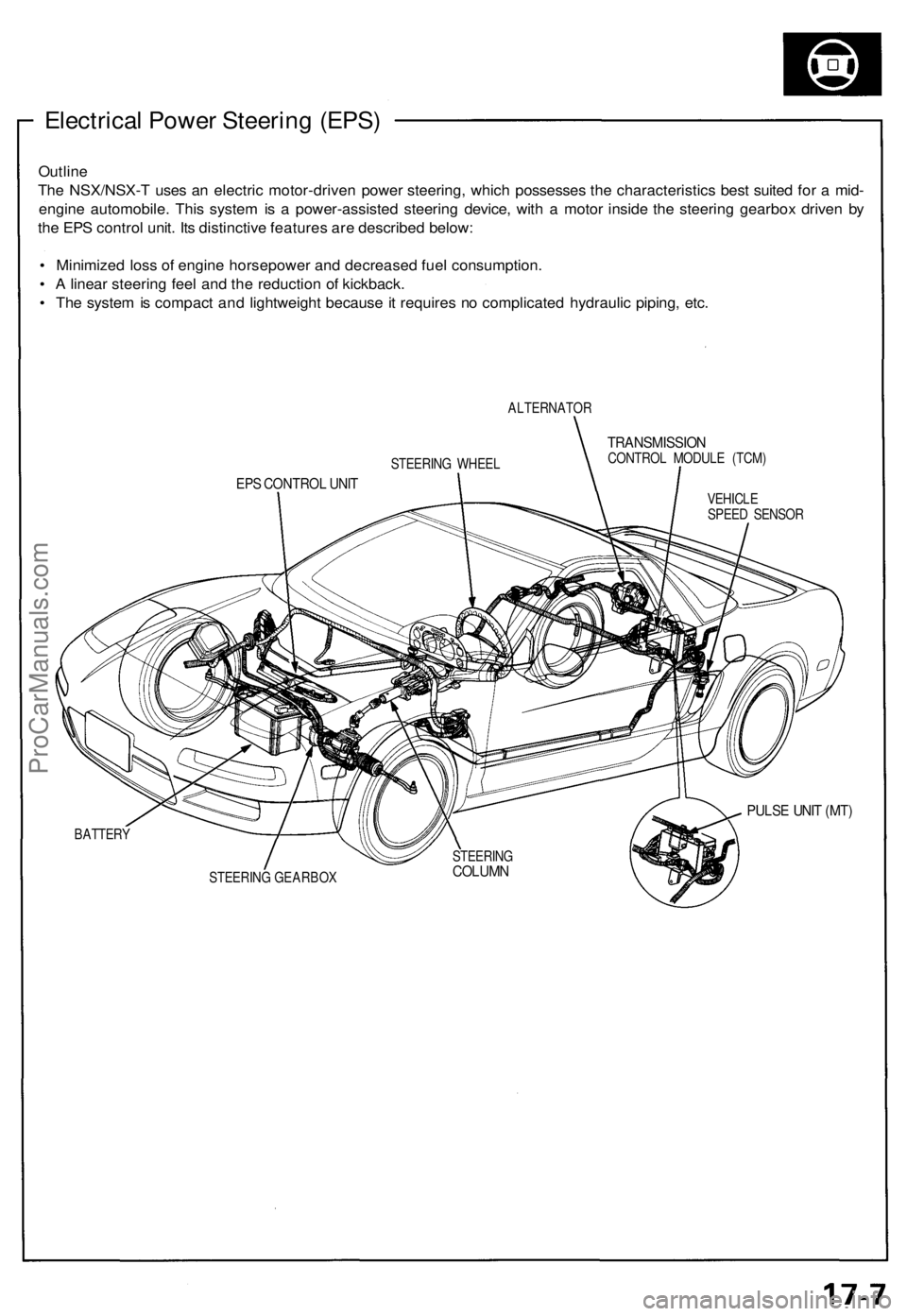
Electrical Power Steering (EPS)
Outline
The NSX/NSX-T uses an electric motor-driven power steering, which possesses the characteristics best suited for a mid-
engine automobile. This system is a power-assisted steering device, with a motor inside the steering gearbox driven by
the EPS control unit. Its distinctive features are described below:
• Minimized loss of engine horsepower and decreased fuel consumption.
• A linear steering feel and the reduction of kickback.
• The system is compact and lightweight because it requires no complicated hydraulic piping, etc.
ALTERNATOR
TRANSMISSION
CONTROL MODULE (TCM)
EPS CONTROL UNIT
VEHICLE
SPEED SENSOR
PULSE UNIT (MT)
BATTERY
STEERING GEARBOX
STEERING WHEEL
STEERING
COLUMNProCarManuals.com
Page 449 of 1640
System Description
Suspension Composition
Outline
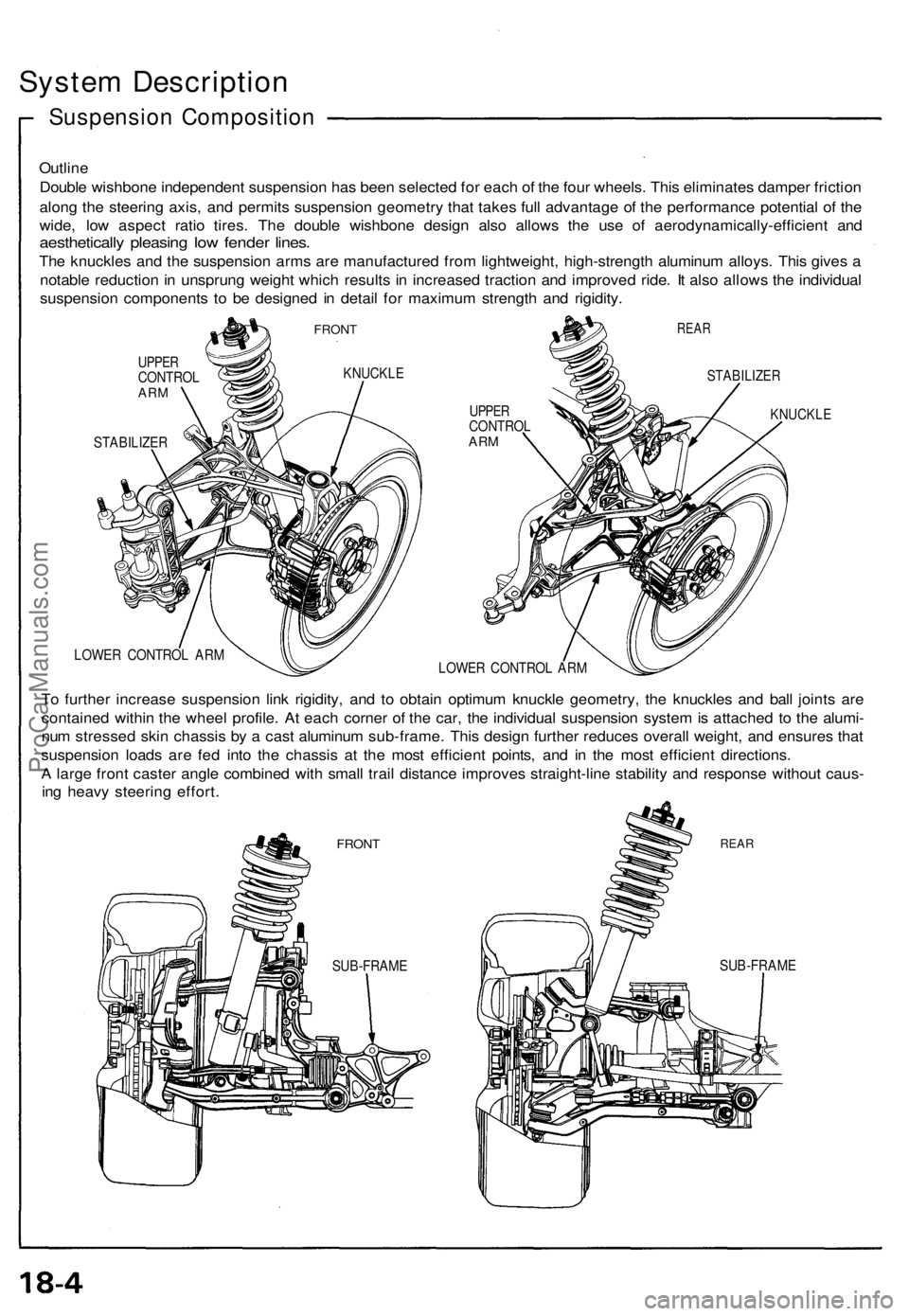
Double wishbone independent suspension has been selected for each of the four wheels. This eliminates damper friction
along the steering axis, and permits suspension geometry that takes full advantage of the performance potential of the
wide, low aspect ratio tires. The double wishbone design also allows the use of aerodynamically-efficient and
aesthetically pleasing low fender lines.
The knuckles and the suspension arms are manufactured from lightweight, high-strength aluminum alloys. This gives a
notable reduction in unsprung weight which results in increased traction and improved ride. It also allows the individual
suspension components to be designed in detail for maximum strength and rigidity.
FRONT
UPPER
CONTROL
ARM
KNUCKLE
STABILIZER
REAR
UPPER
CONTROL
ARM
STABILIZER
KNUCKLE
LOWER CONTROL ARM
LOWER CONTROL ARM
To further increase suspension link rigidity, and to obtain optimum knuckle geometry, the knuckles and ball joints are
contained within the wheel profile. At each corner of the car, the individual suspension system is attached to the alumi-
num stressed skin chassis by a cast aluminum sub-frame. This design further reduces overall weight, and ensures that
suspension loads are fed into the chassis at the most efficient points, and in the most efficient directions.
A large front caster angle combined with small trail distance improves straight-line stability and response without caus-
ing heavy steering effort.
FRONT
REAR
SUB-FRAME
SUB-FRAMEProCarManuals.com
Page 460 of 1640
Hub Replacemen t
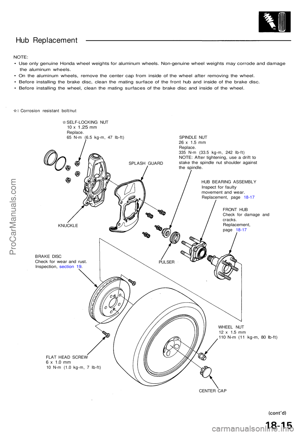
NOTE:
• Us e onl y genuin e Hond a whee l weight s fo r aluminu m wheels . Non-genuin e whee l weight s ma y corrod e an d damag e
th e aluminu m wheels .
• O n th e aluminu m wheels , remov e th e cente r ca p fro m insid e o f th e whee l afte r removin g th e wheel .
• Befor e installin g th e brak e disc , clea n th e matin g surfac e o f th e fron t hu b an d insid e o f th e brak e disc .
• Befor e installin g th e wheel , clea n th e matin g surface s of the brak e dis c an d insid e o f th e wheel .
Corrosio n resistan t bolt/nu t
SELF-LOCKIN G NU T
10 x 1.2 5 mmReplace .
6 5 N- m (6. 5 kg-m , 4 7 Ib-ft ) SPINDL E NU T
26 x 1. 5 m mReplace .
33 5 N- m (33. 5 kg-m , 24 2 Ib-ft )
NOTE : Afte r tightening , us e a drif t t ostak e th e spindl e nu t shoulde r agains tthe spindle .
HUB BEARIN G ASSEMBL YInspect fo r fault ymovemen t an d wear .Replacement , pag e 18-1 7
BRAK E DIS C
Chec k fo r wea r an d rust .Inspection , sectio n 19 .
FRON T HU B
Chec k fo r damag e an d
cracks .
Replacement ,page 18-1 7
WHEE L NU T
12 x 1. 5 m m110 N- m (1 1 kg-m , 8 0 Ib-ft )
FLAT HEA D SCRE W6 x 1. 0 m m10 N- m (1. 0 kg-m , 7 Ib-ft )
CENTER CA P
KNUCKL
E
PULSER
SPLAS H GUAR D
ProCarManuals.com
Page 476 of 1640
Hub Replacemen t
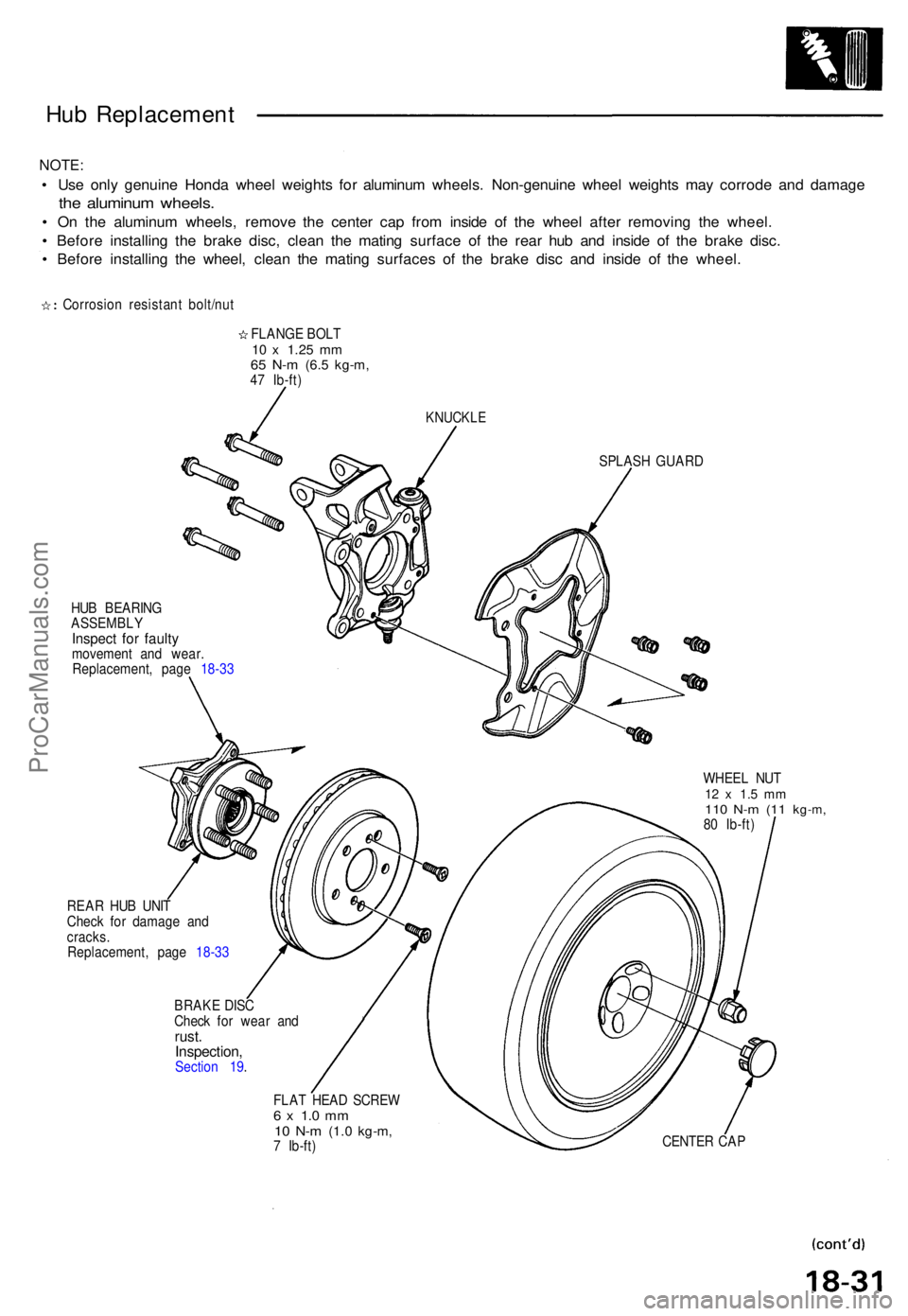
NOTE:
• Us e onl y genuin e Hond a whee l weight s fo r aluminu m wheels . Non-genuin e whee l weight s ma y corrod e an d damag e
the aluminu m wheels .
• O n th e aluminu m wheels , remov e th e cente r cap from insid e o f th e whee l afte r removin g th e wheel .
• Befor e installin g th e brak e disc , clea n th e matin g surfac e o f th e rea r hu b an d insid e o f th e brak e disc .
• Befor e installin g th e wheel , clea n th e matin g surface s o f th e brak e dis c an d insid e o f th e wheel .
Corrosio n resistan t bolt/nu t
FLANG E BOL T
10 x 1.2 5 mm65 N- m (6. 5 kg-m ,47 Ib-ft )
KNUCKL E
SPLASH GUAR D
HU B BEARIN G
ASSEMBL YInspect fo r fault ymovemen t an d wear .
Replacement , pag e 18-3 3
WHEEL NU T
12 x 1. 5 m m110 N- m (1 1 kg-m ,80 Ib-ft )
REA R HU B UNI T
Chec k fo r damag e an d
cracks .
Replacement , pag e 18-3 3
BRAK E DIS C
Chec k fo r wea r an d
rust .Inspection ,Section 19 .
FLAT HEA D SCRE W
6 x 1. 0 m m10 N- m (1. 0 kg-m ,7 Ib-ft ) CENTE
R CA P
ProCarManuals.com