Page 5 of 1640
Warning/Caution Labe l Location s
SRS CAUTIO N LABELS : Refe r t o pag e 1- 6
FROZE NBATTER Y CAUTIO N
AI R CONDITIONIN G
R-134 a CAUTIO N
(U.S.A. only )
ENGIN E COOLAN TCAUTION • PRECAUTIO N
ABS CAUTIO N
ABS an d BRAK EFLUID CAUTIO N
RETRACTABL EHEADLIGHT CAUTIO N
EMISSION CONTRO L
INFORMATIO N an d
VACUU M HOS E
ROUTIN G DIAGRA M
BATTERYCAUTION
RADIATO R BLEE DPLUG CAUTIO N
EXPANSIO NTANK CA PCAUTIO N
SPAR K PLU G
CAUTIO N
TIRE INFORMATIO N
ProCarManuals.com
Page 426 of 1640

Steering Whee l
Remova l
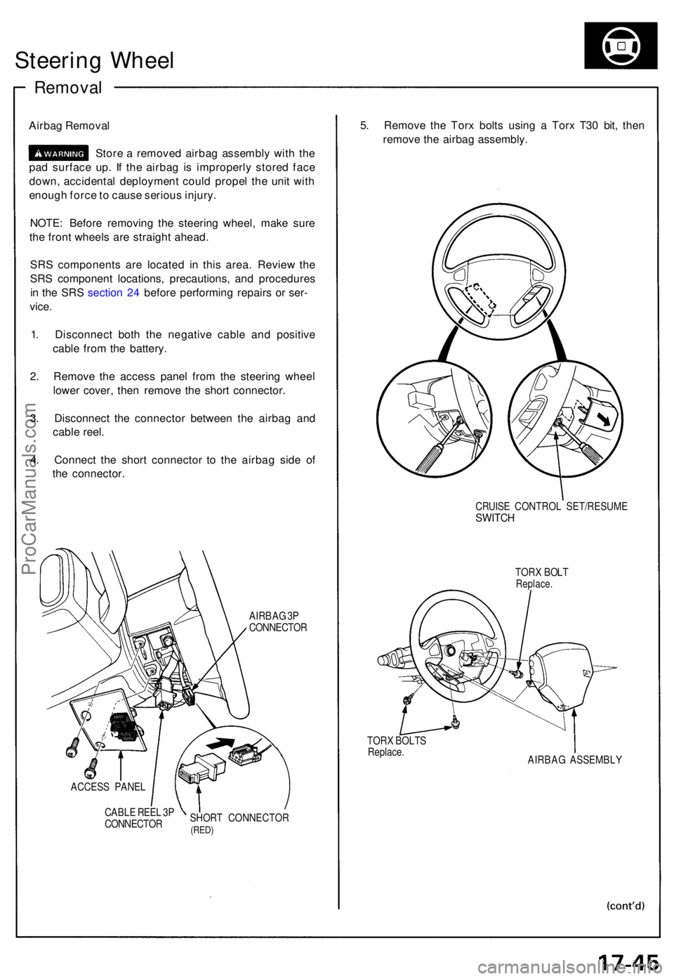
Airbag Remova l
Stor e a remove d airba g assembl y wit h th e
pa d surfac e up . I f th e airba g i s improperl y store d fac e
down , accidenta l deploymen t coul d prope l th e uni t wit h
enoug h forc e to caus e seriou s injury .
NOTE : Befor e removin g th e steerin g wheel , mak e sur e
th e fron t wheel s ar e straigh t ahead .
SR S component s ar e locate d i n thi s area . Revie w th e
SR S componen t locations , precautions , an d procedure s
i n th e SR S sectio n 24 befor e performin g repair s o r ser -
vice .
1 . Disconnec t bot h th e negativ e cabl e an d positiv e
cabl e fro m th e battery .
2 . Remov e th e acces s pane l fro m th e steerin g whee l
lowe r cover , the n remov e th e shor t connector .
3 . Disconnec t th e connecto r betwee n th e airba g an d
cabl e reel .
4 . Connec t th e shor t connecto r t o th e airba g sid e o f
th e connector .
AIRBAG 3P
CONNECTO R
ACCES S PANE L
CABL E REE L 3 P
CONNECTO RSHOR
T CONNECTO R
(RED)
5. Remov e th e Tor x bolt s usin g a Tor x T3 0 bit , the n
remov e th e airba g assembly .
TORX BOLT SReplace .
CRUISE CONTRO L SET/RESUM ESWITCH
TORX BOL TReplace .
AIRBAG ASSEMBL Y
ProCarManuals.com
Page 431 of 1640

Steering Colum n
Remova l
SRS component s ar e locate d i n thi s area . Revie w th e
SR S componen t locations , precautions , an d procedure s
i n th e SR S sectio n 24 befor e performin g repair s o r ser -
vice .
1 . Disconnec t bot h th e negativ e cabl e an d positiv e
cabl e fro m th e battery .
2 . Remov e th e airba g assembl y an d steerin g whee l
fro m th e colum n (se e pag e 17-45 ).
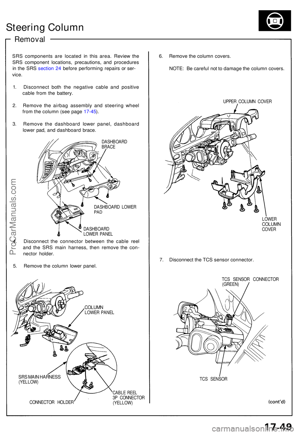
3 . Remov e th e dashboar d lowe r panel , dashboar d
lowe r pad , an d dashboar d brace .
DASHBOAR DBRACE
DASHBOAR D LOWE RPAD
DASHBOAR D
LOWE R PANE L
4. Disconnec t th e connecto r betwee n th e cabl e ree l
an d th e SR S mai n harness , the n remov e th e con -
necto r holder .
5 . Remov e th e colum n lowe r panel .
COLUM NLOWER PANE L
SRS MAI N HARNES S(YELLOW )
CONNECTO R HOLDE R
CABLE REE L3P CONNECTO R(YELLOW)
6. Remov e th e colum n covers .
NOTE : B e carefu l no t t o damag e th e colum n covers .
UPPER COLUM N COVE R
LOWERCOLUM NCOVER
7. Disconnec t th e TC S senso r connector .
TCS SENSO R CONNECTO R
(GREEN )
TC S SENSO R
ProCarManuals.com
Page 437 of 1640

Steering Gearbox
Removal/Installation
NOTE: Before removing the steering gearbox, make
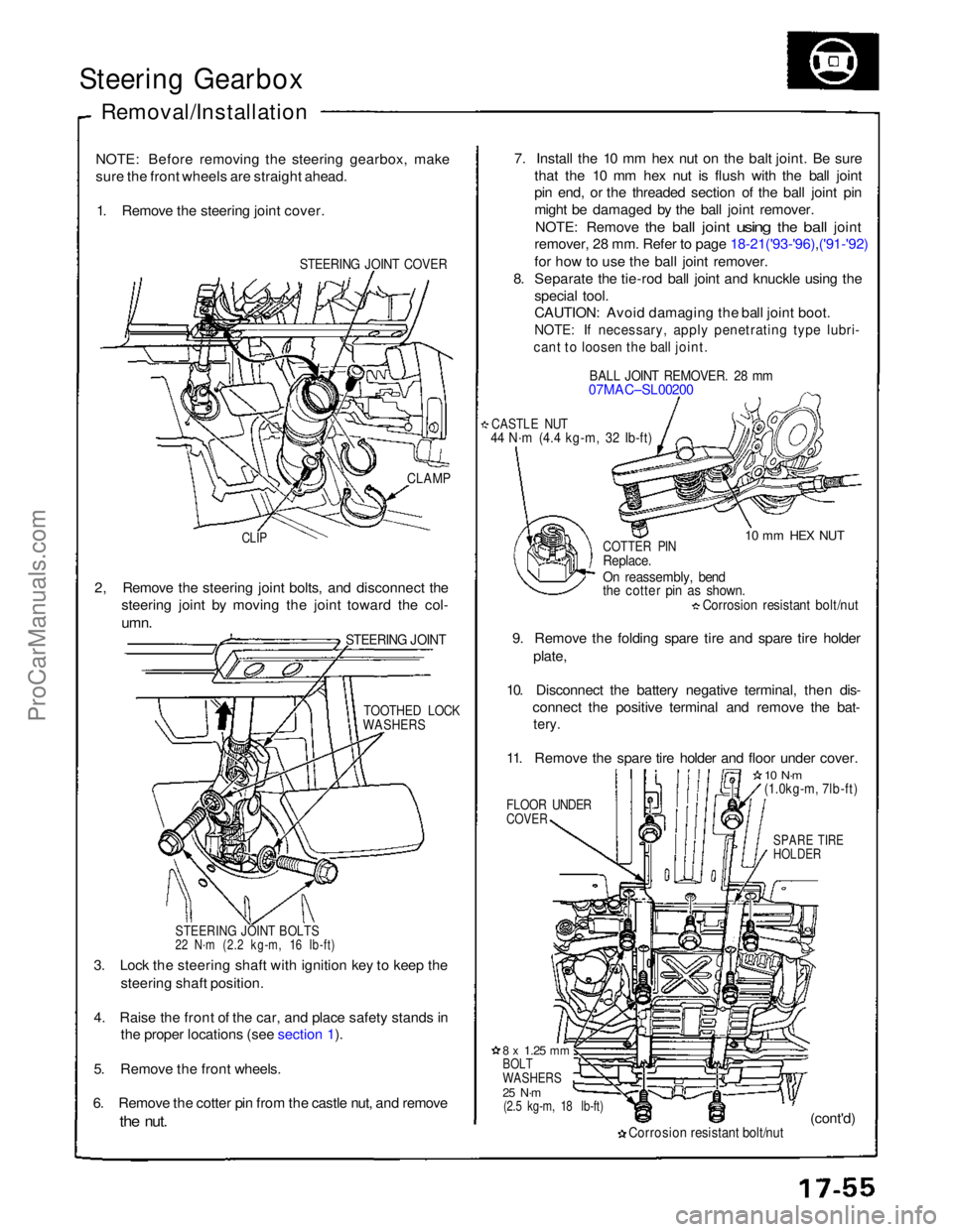
sure the front wheels are straight ahead. 1. Remove the steering joint cover.
STEERING JOINT COVER
7. Install the 10 mm hex nut on the balt joint. Be sure
that the 10 mm hex nut is flush with the ball joint
pin end, or the threaded section of the ball joint pin
might be damaged by the ball joint remover.
NOTE: Remove
the
ball
joint
using
the
ball
joint
remover, 28 mm. Refer to page 18-21('93-'96),('91-'92)
for how to use the ball joint remover.
8. Separate the tie-rod ball joint and knuckle using the
special tool.
CAUTION: Avoid damaging the ball joint boot.
NOTE: If necessary, apply penetrating type lubri-
cant to loosen the ball joint.
BALL JOINT REMOVER. 28 mm
07MAC–SL00200
CASTLE NUT
44 N·m (4.4 kg-m, 32 Ib-ft)
10 mm HEX NUT
CLAMP
CLIP
COTTER PIN
Replace.
On reassembly, bend
the cotter pin as shown.
Corrosion resistant bolt/nut
9. Remove the folding spare tire and spare tire holder plate,
10. Disconnect the battery negative terminal, then dis- connect the positive terminal and remove the bat-
tery.
11. Remove the spare tire holder and floor under cover.
FLOOR UNDER
COVER
10 N·m
(1.0kg-m, 7lb-ft)
SPARE TIRE
HOLDER
2, Remove the steering joint bolts, and disconnect the
steering joint by moving the joint toward the col-
umn.
STEERING JOINT
TOOTHED LOCK
WASHERS
STEERING JOINT BOLTS
22 N·m (2.2 kg-m, 16 Ib-ft)
3. Lock the steering shaft with ignition key to keep the steering shaft position.
4. Raise the front of the car, and place safety stands in the proper locations (see section 1).
5. Remove the front wheels.
6. Remove the cotter pin from the castle nut, and remove
the
nut.
8 x
1.25
mm
BOLT
WASHERS
25 N·m
(2.5 kg-m, 18 lb-ft)
Corrosion resistant bolt/nut
(cont'd)ProCarManuals.com
Page 741 of 1640
Under-dash Fus e Bo x
Removal/Installatio n
SRS component s ar e locate d in thi s area . Revie w th e SR S
componen t locations , precautions , an d procedure s in th e
SR S sectio n 24 befor e performin g repair s o r service .
Removal :
1. Disconnec t bot h th e negativ e cabl e an d positiv e
cabl e fro m th e battery .
2 . Carefull y remov e th e sid e sil l pa d (pul l i t up , rea r
en d first) .
3 . Remov e th e fus e bo x door .
FUSE BO XDOO R
SIDE SIL L PA D
SIDE SIL L TRI M
4. Remov e th e thre e screws , the n remov e th e sid e sil l
trim .
5. Remov e th e under-das h fus e bo x mountin g bolts . 6
. Disconnec t th e under-das h fus e bo x connectors .
NOTE : Th e SR S mai n harnes s connecto r i s doubl e
locked . T o remov e it , firs t lif t th e connecto r lid ,
the n pres s th e connecto r ta b dow n an d pul l th e
connecto r out .
TAB
SR S MAI N HARNES S
7. Tak e ou t th e under-das h fus e box .
ProCarManuals.com
Page 945 of 1640

Security Alarm System
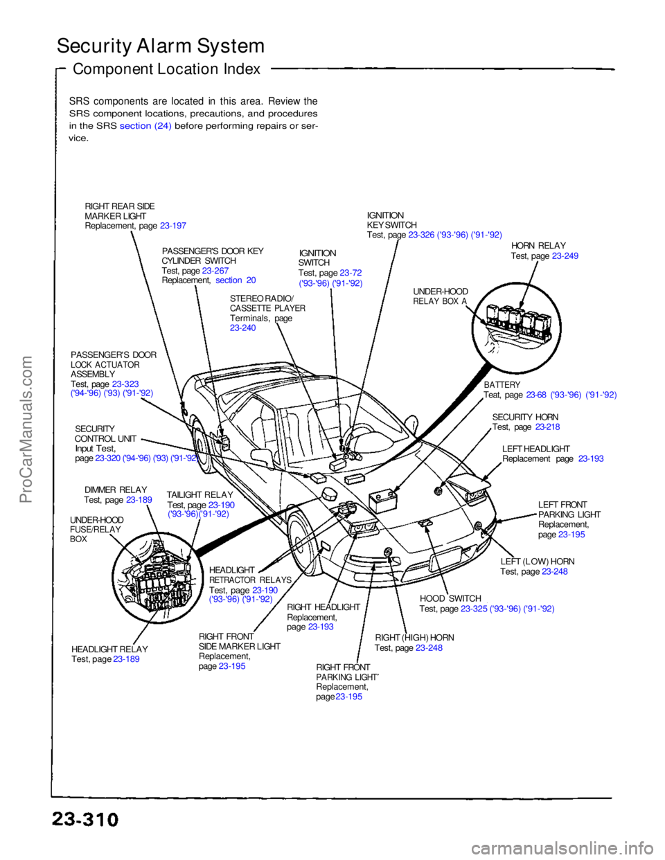
Component Location Index
SRS components are located in this area. Review the
SRS component locations, precautions, and procedures
i
n
the SRS section (24) before performing repairs or ser-
vice.
RIGHT REAR SIDE
MARKER LIGHT
Replacement, page 23-197 PASSENGER'S DOOR KEY
CYLINDER SWITCH
Test, page 23-267
Replacement, section 20
STEREO RADIO/
CASSETTE PLAYER
Terminals, page
23-240
IGNITION
SWITCH
Test, page 23-72
('93-'96) ('91-'92)
IGNITION
KEY SWITCH
Test, page 23-326 ('93-'96) ('91-'92)
UNDER-HOOD
RELAY BOX A
HORN RELAY
Test, page 23-249
BATTERY
Teat, page 23-68 ('93-'96) ('91-'92)
SECURITY HORN
Test, page 23-218 LEFT HEADLIGHT
Replacement page 23-193
LEFT FRONT
PARKING LIGHT
Replacement,
page 23-195
LEFT (LOW) HORN
Test, page 23-248
HOOD SWITCH
Test, page 23-325 ('93-'96) ('91-'92)
RIGHT (HIGH) HORN
Test, page 23-248
RIGHT FRONT
PARKING LIGHT
Replacement,
page 23-195
RIGHT HEADLIGHT
Replacement,
page 23-193
RIGHT FRONT
SIDE MARKER LIGHT
Replacement,
page 23-195 HEADLIGHT
RETRACTOR RELAYS
Test, page 23-190
('93-'96) ('91-'92)
HEADLIGHT RELAY
Test, page 23-189 TAILIGHT RELAY
Test, page 23-190
('93-'96)('91-'92)
UNDER-HOOD
FUSE/RELAY
BOX
DIMMER RELAY
Test, page 23-189
SECURITY
CONTROL UNIT
Input Test,
page 23-320 ('94-'96) ('93) ('91-'92)
PASSENGER'S DOOR
LOCK ACTUATOR
ASSEMBLY
Test, page 23-323
('94-'96) ('93) ('91-'92)ProCarManuals.com
Page 960 of 1640
Warning/Caution Label Locations
SRS CAUTION LABELS: Refer to page 1-8.
FROZEN
BATTERY CAUTION
BATTERY
CAUTION
RADIATOR BLEED
PLUG CAUTION
AIR CONDITIONING
R-134a CAUTION (U.S.A only)
EXPANSION
TANK CAP
CAUTION
ENGINE COOLANT CAUTION PRECAUTION
SPARK PLUG
CAUTION
TIRE INFORMATION
ABS CAUTION
ABS and BRAKE
FLUID CAUTION
RETRACTABLE
HEADLIGHT CAUTION
EMISSION CONTROL
INFORMATION and
VACUUM HOSE
ROUTING DIAGRAM
(cont'd)ProCarManuals.com
Page 969 of 1640
Warning/Caution Label Locations
SRS CAUTION LABELS: Refer to page 1-8.
FROZEN
BATTERY CAUTION
BATTERY
CAUTION
RADIATOR BLEED
PLUG CAUTION
AIR CONDITIONING R-134a CAUTION(U.S.A only)
EXPANSION
TANK CAP CAUTION
ENGINE COOLANT
CAUTION • PRECAUTION
SPARK PLUG
CAUTION
TIRE INFORMATION
EMISSION CONTROL
INFORMATION and
VACUUM HOSE
ROUTING DIAGRAM
RETRACTABLE
HEADLIGHT CAUTION
ABS and BRAKE
FLUID CAUTION ABS CAUTION
(cont'd)ProCarManuals.com