1991 ACURA NSX door lock
[x] Cancel search: door lockPage 564 of 1640

Doors
REAR SASH
Adjustment, see page 20-17('93-'96),16('91-'92)
REAR GLASS
GUIDE
Index
FRONT GLASS
GUIDE
REGULATOR
ASSEMBLY
INNER MOLDING STOPPER
PLATES GLASS
Adjustment, see page 20-14('93-'96),
13('91-'92)
FRONT SASH
Adjustment, see page 20-17('93-'96),
16('91-'92)
POWER MIRROR
INSIDE STABILIZERS OUTER MOLDING
DOOR HINGE
POWER WINDOW
MOTOR
LOCK
CYLINDER
DOOR
Disassembly, see page 20-7
('93-'96),6('91-'92)
Assembly, see page 20-13
('93-'96),12('91-'92)
Adjustment, see page 20-19
('93-'96),18('91-'92)
STRIKER
Adjustment, see page 20-19
('93-'96),18('91-'92)
LOCK ROD
LATCH
ASSEMBLY INNER HANDLE HANDLE CABLE
TRIM PLATE POWER DOOR
LOCK SWITCHDOOR
PANEL
LOCK
CRANK
PLASTIC
COVER
DETENT
ROD
LOWER
WEATHERSTRIP
INNER
WEATHERSTRIP
AIR DUCT
Passenger's:
SWITCH PANEL
ARMREST
COURTESY
LIGHT
SWITCH PANEL
POWER WINDOW
SWITCHProCarManuals.com
Page 567 of 1640

9. Remove the mounting screws, then remove the
front sash panel from the front sash.
FRONT SASH
FRONT SASH PANEL
MOUNTING
SCREW
10. Remove the outer molding (see page 20-12
('93-'96),11('91-'92)
11. Remove the mounting bolts and locknut, then
remove the front sash.
NOTE:
Hold the adjusting bolt with
a hex wrench when
removing the locknut.
Scribe a line around the locknut to show the
original adjustment.
LOCKNUT
FRONT SASH
ADJUSTING BOLT
MOUNTING BOLT
6 x 1.0 mm
8 N·m
(0.8 kg-m,
5.8 lb-ft)
MOUNTING BOLT
*6
x 1.0 mm
8 N·m
(0.8 kg-m,
5.8 Ib-ft)
LOCKNUT
*8 x 1.25 mm
22 N·m(2.2kg-m,
16 Ib-ft)
LOCKNUT
: CORROSION RESISTANT BOLT/NUT
12. Remove the mounting bolt, locknut and adjusting
bolt. Remove the rear sash, then disconnect the
handle rod.
NOTE:
Before removing the adjusting bolt, measure and
record the clearance between the rear sash
and door.
Scribe a line around the locknut to show the
original adjustment.
Take care not to bend the handle rod.
HANDLE RODREAR SASH
REAR
SASH
DOOR
LOCKNUT
ADJUSTING
BOLT
MOUNTING BOLT
*6 x 1.0 mm
8 N·m
40.8 kg-m,
5.8 Ib-ft)
LOCKNUT
*8 x
1.25
mm
22 N·m
(2.2 kg-m,
16 Ib-ft)
*: CORROSION RESISTANT 80LT/NUT
13. To replace the outer handle, remove the mounting
screws from the rear sash.
NOTE: Apply grease to the moving surfaces.
OUTER HANDLE
MOUNTING
SCREW
CAP
REAR SASH
(cont'd)ProCarManuals.com
Page 568 of 1640

Doors
Disassembl y
14. Remov e th e locknuts , the n remov e th e rea r glas s
guide .
NOTE :
• Hol d th e adjustin g bol t wit h a he x wrenc h whe n
removin g th e locknuts .
• Scrib e a lin e aroun d th e locknut s t o sho w th e
origina l adjustment .
LOCKNUT
LOCKNUT S
8 x 1.2 5 mm22 N- m (2. 2 kg-m ,16 Ib-ft )
CORROSIO N RESISTAN T BOLT/NU T
15. Befor e removin g th e latc h assembl y an d loc k
cylinder , rais e th e glas s full y b y connectin g a 1 2 V
batter y t o th e powe r windo w moto r (se e
section 23 ).
16 . Remov e th e retaine r b y slidin g i t forward . Pr y th e
cylinde r ro d ou t it s join t usin g a fla t ti p screwdriver ,
the n carefull y remov e th e loc k cylinder .
NOTE : Tak e car e no t t o ben d th e cylinde r rod .
LOC K CYLINDE R
CYLINDE R RO D
17. Disconnec t th e loc k ro d an d remov e th e loc k crank .
Remov e th e handl e cabl e an d clips .
Remov e th e mountin g screws , the n remov e th e
latc h assembl y throug h th e hol e i n th e door .
NOTE : Tak e car e no t t o ben d th e loc k ro d an d han -
dl e cable .
LATCH ASSEMBL Y
HANDLE CABL E
MOUNTIN G SCRE W
6 x 1. 0 m m5 N- m (0. 5 kg-m ,3.6 Ib-ft )
CLIPS
LOC K CRAN K
LOC K RO D
18. Lowe r th e glas s an d remov e th e mountin g nuts ,
the n remov e th e stoppe r plates .
NOTE:
• Lowe r th e glas s b y connectin g a 1 2 V batter y t o
th e powe r windo w moto r (se e sectio n 23 ).
• Scrib e a lin e aroun d th e mountin g nut s t o sho w
th e origina l adjustment .
STOPPER PLATE S
MOUNTIN G NU T8 x 1.2 5 mm22 N- m (2. 2 kg-m ,16 Ib-ft )
MOUNTIN GNUT
RETAINE R
GLASS
CYLINDE R RO D ADJUSTIN
G BOL T
REA
R GLAS S GUID E
ProCarManuals.com
Page 569 of 1640

19. Carefull y lowe r th e glas s unti l yo u ca n se e it s
mountin g bolts , the n remov e them . Pul l th e glas s
out throug h th e windo w slot .
NOTE :
• Lowe r th e glas s b y connectin g a 1 2 V batter y t o
th e powe r windo w moto r (se e sectio n 23 ).
• Scrib e a lin e aroun d th e mountin g bolt s t o sho w
th e origina l adjustment .
GLASS
GLAS S GUID E
MOUNTING BOLT S
6 x 1. 0 m m8 N- m (0. 8 kg-m ,5.8 Ib-ft )
CORROSIO N RESISTAN T
BOL T
20. Remov e th e locknuts , the n remov e th e fron t glas s
guide .
NOTE :
• Hol d th e adjustin g bol t wit h a he x wrenc h whe n
removin g th e locknuts .
• Scrib e a lin e aroun d th e locknut s t o sho w th e
origina l adjustment .
FRONT GLAS S GUID E LOCKNU T
LOCKNUT S
8 x 1.2 5 mm22 N- m (2. 2 kg-m ,16 Ib-ft )
21. Remov e th e mountin g bolt s an d loose n th e moto r
mountin g bolts , the n tak e ou t th e regulato r
assembl y throug h th e windo w slot .
NOTE :
• Scrib e a lin e aroun d th e mountin g bolt s t o sho w
th e origina l adjustment .
• Tak e car e no t t o ben d th e cables .
CABLES
MOTOR MOUNTIN GBOLTS6 x 1. 0 m m 8 N- m(0.8 kg-m , 5. 8 Ib-ft )Loosen .
MOUNTIN G BOLT S6 x 1. 0 m m8 N- m (0. 8 kg-m ,5.8 Ib-ft )
MOUNTIN GBOLT
CORROSIO N RESISTAN T BOL T
22. Remov e th e mountin g bolts , the n remov e th e insid e
stabilizer s fro m th e door .
NOTE : Scrib e a lin e aroun d th e mountin g bolt s t o
sho w th e origina l adjustment .
INSIDE STABILIZER S
MOUNTING BOL T8 x 1.2 5 mm22 N- m (2. 2 kg-m , 1 6 Ib-ft )
MOUNTIN GBOLT
CORROSIO N RESISTAN T BOL T
GLAS
S GLAS
S
ProCarManuals.com
Page 574 of 1640

Doors
Glass Adjustment (cont'd)
"H" (See page 20-15('93-'96),14('91-'92)
GLASS
a. Loosen the bolts and nuts securing the front sash, rear sash and stopper plates, then move the front
sash all the way forward and move the rear sash
all the way backward.
NOTE: Hold the adjusting bolts with a hex
wrench when loosening the locknuts.
FRONT
SASH
LOCKNUT
REAR SASH STOPPER PLATES
ADJUSTING
BOLT
b. Loosen the bolts securing the regulator assem- bly, and move the regulator assembly fore or aft
to align the glass with the body at the front and
center pillars.
GLASS
Loosen.
REGULATOR ASSEMBLY
c. Loosen the nuts securing the rear glass guide, and
adjust the glass fore and aft by moving the rear
glass guide.
NOTE: Hold the adjusting bolts with a hex
wrench when loosening the locknuts.
GLASS
REAR GLASS GUIDE
ADJUSTING
BOLT
d. Repeat steps b and c until clearance "H" is
within
the
specified
limits,
then secure
the
regu-
lator and glass guide. Press the stopper plates
against the glass stoppers, then secure the stop-
per plates.
NOTE: Check that the stopper plates contact the
glass stoppers evenly.
STOPPER PLATE
MOUNTING
NUT
GLASS STOPPER
8. Adjust the Clearance "H" as follows:
Loosen.
Loosen.
Loosen.
Loosen.
Loosen,
LOCKNUTProCarManuals.com
Page 575 of 1640
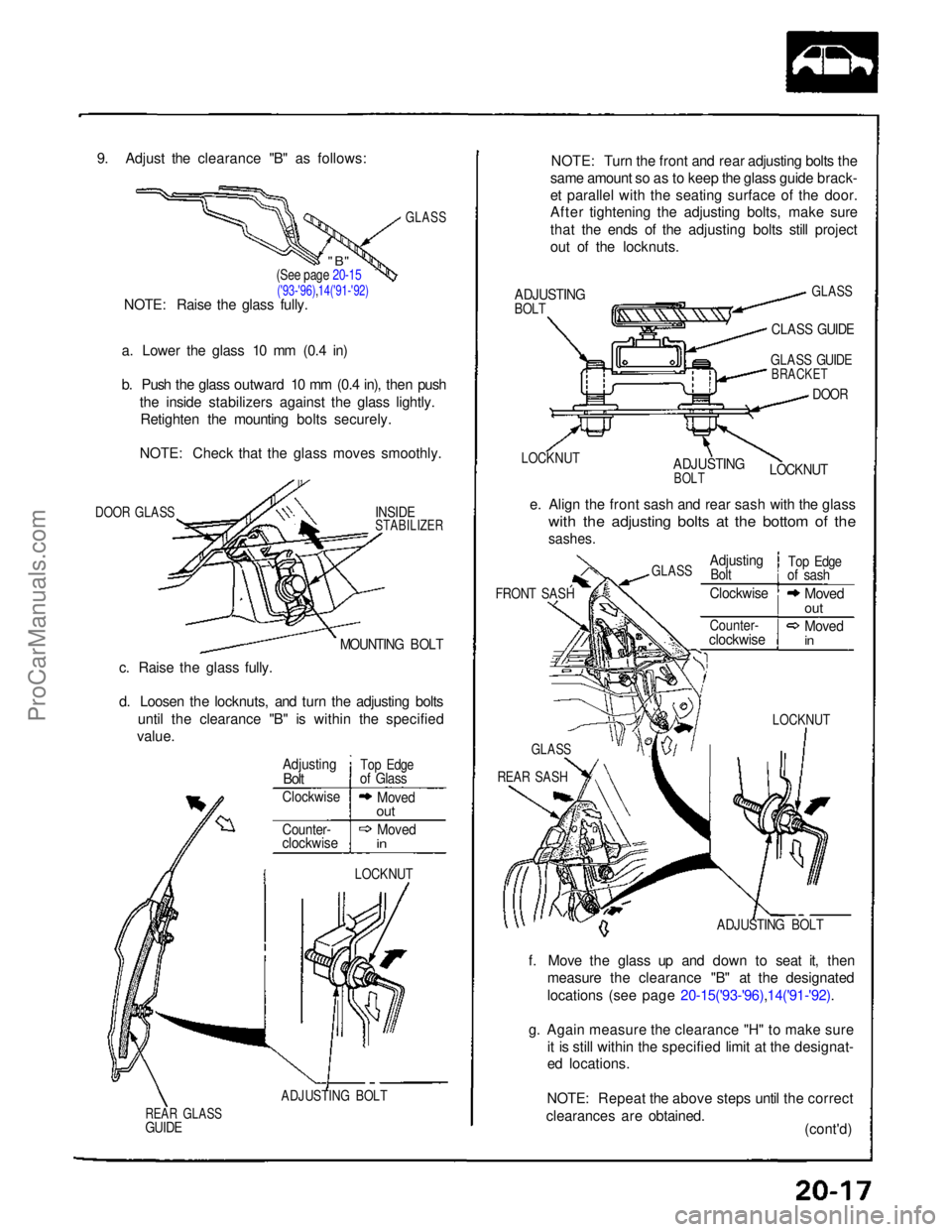
9. Adjust the clearance "B" as follows:
GLASS
a. Lower the glass 10 mm (0.4 in)
b. Push the glass outward 10 mm (0.4 in), then push the inside stabilizers against the glass lightly.Retighten the mounting bolts securely.
NOTE: Check that the glass moves smoothly.
DOOR GLASS
INSIDE
STABILIZER
MOUNTING BOLT
c. Raise the glass fully.
d. Loosen the locknuts, and turn the adjusting bolts until the clearance "B" is within the specified
value.
LOCKNUT
ADJUSTING BOLT
REAR GLASS
GUIDE
NOTE: Turn the front and rear adjusting bolts the
same amount so as to keep the glass guide brack-
et parallel with the seating surface of the door.
After tightening the adjusting bolts, make sure
that the ends of the adjusting bolts still project
out of the locknuts.
ADJUSTING
BOLT
GLASS
CLASS GUIDE
LOCKNUT
ADJUSTING
BOLT
GLASS GUIDE
BRACKET
DOOR
LOCKNUT
e. Align the front sash and rear sash with the glass
with the adjusting bolts at the bottom of the
sashes.
FRONT SASH
ADJUSTING BOLT
f. Move the glass up and down to seat it, then measure the clearance "B" at the designated
locations (see page 20-15('93-'96),14('91-'92).
g. Again measure the clearance "H" to make sure it is still within the specified limit at the designat-
ed locations.
NOTE: Repeat the above steps until the correct
clearances are obtained. (cont'd)
(See page 20-15
('93-'96),14('91-'92)
NOTE: Raise the glass fully.
Adjusting
Bolt
Top Edge
of Glass
Clockwise
Moved
out
Counter-
clockwise
Moved
in
LOCKNUT
GLASS
REAR SASH
GLASS
Adjusting
Bolt
Top Edge
of sash
Clockwise
Moved
out
Counter-
clockwise
Moved
in
"B"ProCarManuals.com
Page 671 of 1640
16. Chec k tha t eac h roo f sid e loc k handl e work s
smoothly .
17. Remov e th e roof .
18 . I f th e roo f sid e retaine r ha s no t bee n replaced , an d
o r th e EP T seale r o n th e roo f sid e retaine r ha s no t
bee n replaced , d o th e followin g (se e pag e 20-84 ):
a . Remov e th e roo f sid e sea l an d roo f sid e retaine r
fro m th e roof .
b . Replac e th e EP T seale r o n th e roo f sid e retaine r
an d roof .
c . Replac e th e buty l tape s o n th e roo f sid e seal .
d . Reinstal l th e roo f sid e retainer , the n appl y ne w
sealant .
e . Reinstal l th e roo f sid e seal .
19 . Chec k th e lip s o f th e roo f sid e seal , an d glu e th e
peele d li p securel y wit h sealant , the n wip e th e
exces s sealan t of f wit h a sof t sho p towe l dampene d
with alcohol .
20. Afte r applyin g th e sealant , le t th e roo f stan d fo r a t
leas t thre e hours .
21 . Instal l th e roo f o n th e body , the n mak e sur e th e
seal s fi t flush .
NOTE : Mak e sur e bot h roo f sid e loc k handle s ar e
locke d securely .
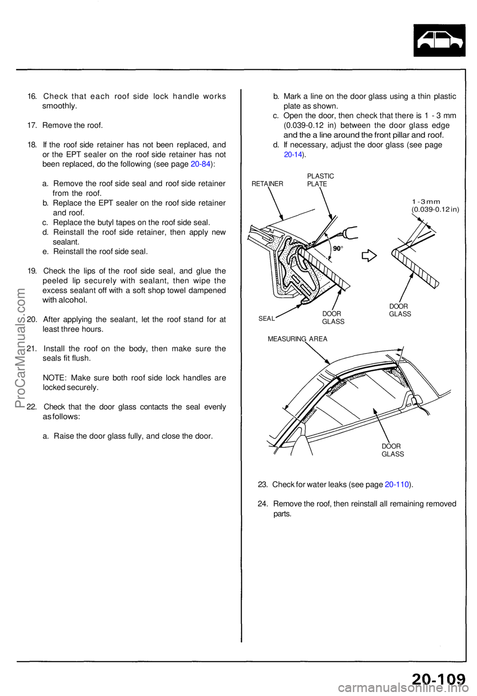
22 . Chec k tha t th e doo r glas s contact s th e sea l evenl y
as follows :
a. Rais e th e doo r glas s fully , an d clos e th e door . b
. Mar k a lin e o n th e doo r glas s usin g a thi n plasti c
plat e a s shown .
c . Ope n th e door , the n chec k tha t ther e is 1 - 3 m m
(0.03 9-0.1 2 in ) betwee n th e doo r glas s edg e
and th e a lin e aroun d th e fron t pilla r an d roof .
d. I f necessary , adjus t th e doo r glas s (se e pag e
20-14 ).
RETAINE RPLASTICPLATE
1 - 3 m m(0.039-0.1 2 in )
SEA L
MEASURIN G ARE A
DOORGLAS S
DOORGLAS S
DOORGLAS S
23. Chec k fo r wate r leak s (se e pag e 20-110 ).
24 . Remov e th e roof , the n reinstal l al l remainin g remove d
parts .
ProCarManuals.com
Page 672 of 1640
Water Lea k Tes t
NOTE : Whe n th e followin g part s hav e bee n replace d o r
removed , an d o r th e roo f sid e loc k unit , doo r glas s an d
doo r hav e bee n adjusted , thi s wate r lea k tes t shoul d b e
done .
• Roo f sid e seal s
• Roo f sid e loc k unit s
• Fron t an d rea r pilla r seal s
• Doo r an d doo r glas s
1 . Mak e sur e tha t th e roo f i s locke d securely .
2 . Rais e th e glas s fully , an d clos e th e doors .
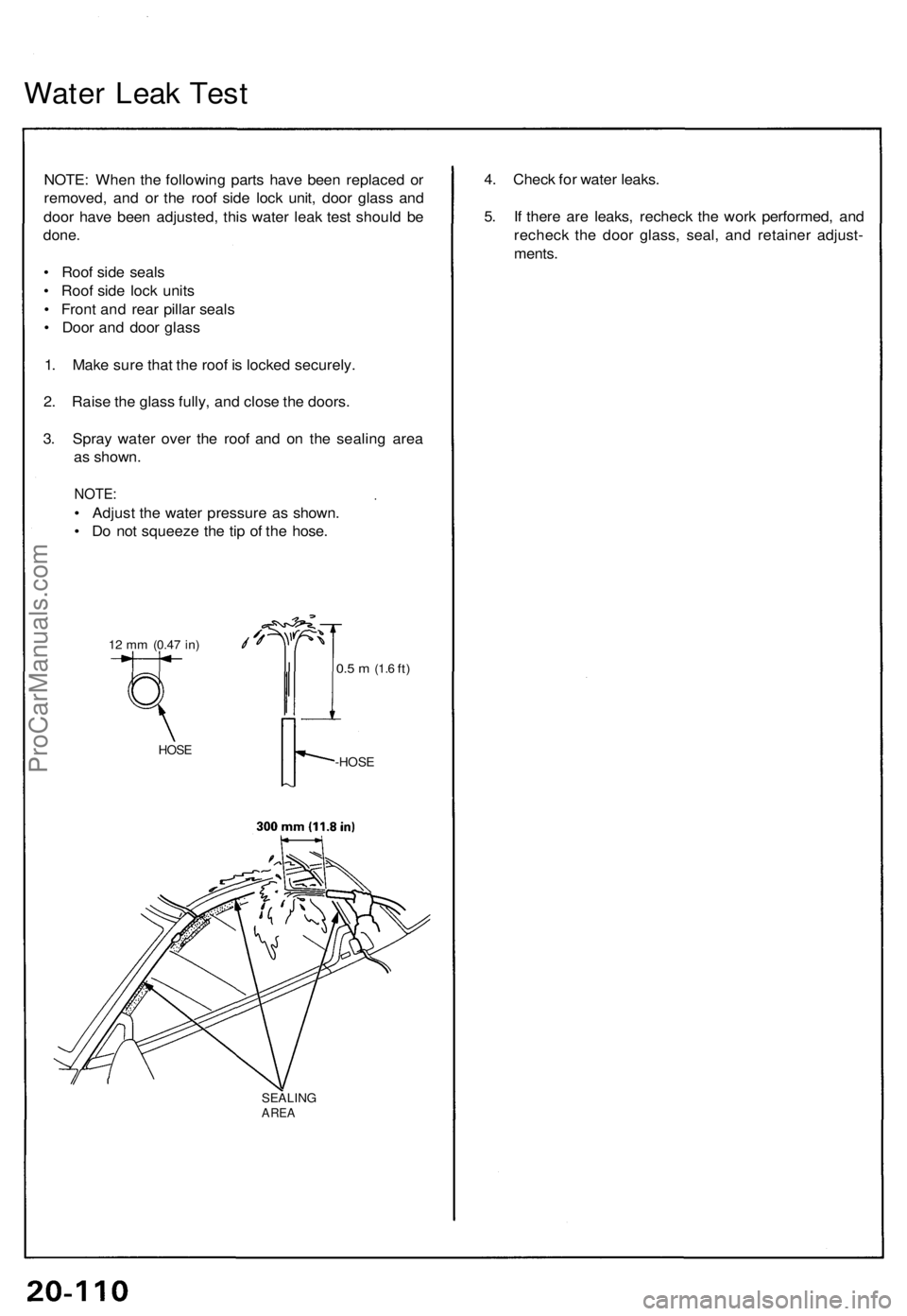
3 . Spra y wate r ove r th e roo f an d o n th e sealin g are a
a s shown .
NOTE:
• Adjus t th e wate r pressur e a s shown .
• D o no t squeez e th e ti p o f th e hose .
12 m m (0.4 7 in)
HOS E
0.5 m (1. 6 ft)
-HOS E
SEALIN GAREA
4. Chec k fo r wate r leaks .
5 . I f ther e ar e leaks , rechec k th e wor k performed , an d
rechec k th e doo r glass , seal , an d retaine r adjust -
ments .
ProCarManuals.com